QATAR UNIVERSITY
COLLEGE OF ENGINEERING
FAULT DIAGNOSIS OF SENSOR AND ACTUATOR FAULTS IN MULTI-ZONE HVAC SYSTEMS
BY
MARIAM AHMED ELNOUR
A Thesis Submitted to
the Faculty of the College of Engineering
in Partial Fulfillment of the Requirements for the Degree of Masters of Science in Electrical Engineering
June 2019
COMMITTEE PAGE
The members of the Committee approve the Thesis of Mariam Elnour defended on 16/04/2019. Dr. Nader Meskin Thesis Supervisor Dr. Mohammed Al-Naemi Thesis Co-supervisor Dr. Marios M. Polycarpou Committee Member Dr. Mustafa S. Kiranyaz Committee Member Approved:
ABSTRACT
ELNOUR, MARIAM, A., Masters :
June : 2019, Master of Science in Electrical Engineering
Title: Fault Diagnosis of Sensor and Actuator Faults in Multi-Zone HVAC Systems Supervisors of Thesis: Dr. Nader, M, Meskin and Dr. Mohammed, I, Al-Naemi.
Globally, the buildings sector accounts for 30% of the energy consumption and more than 55% of the electricity demand. Specifically, the Heating, Ventilation, and Air Conditioning (HVAC) system is the most extensively operated component and it is responsible alone for 40% of the final building energy usage. HVAC systems are used to provide healthy and comfortable indoor conditions, and their main objective is to maintain the thermal comfort of occupants with minimum energy usage.
HVAC systems include a considerable number of sensors, controlled actuators, and other components. They are at risk of malfunctioning or failure resulting in reduced effi-ciency, potential interference with the execution of supervision schemes, and equipment deterioration. Hence, Fault Diagnosis (FD) of HVAC systems is essential to improve their reliability, efficiency, and performance, and to provide preventive maintenance.
In this thesis work, two neural network-based methods are proposed for sensor and actuator faults in a 3-zone HVAC system. For sensor faults, an online semi-supervised sensor data validation and fault diagnosis method using an Auto-Associative Neural Network (AANN) is developed. The method is based on the implementation of Non-linear Principal Component Analysis (NPCA) using a Back-Propagation Neural Net-work (BPNN) and it demonstrates notable capability in sensor fault and inaccuracy correction, measurement noise reduction, missing sensor data replacement, and in both single and multiple sensor faults diagnosis. In addition, a novel on-line supervised
multi-model approach for actuator fault diagnosis using Convolutional Neural Net-works (CNNs) is developed for single actuator faults. It is based a data transformation in which the 1-dimensional data are configured into a 2-dimensional representation with-out the use of advanced signal processing techniques. The CNN-based actuator fault diagnosis approach demonstrates improved performance capability compared with the commonly used Machine Learning-based algorithms (i.e., Support Vector Machine and standard Neural Networks).
The presented schemes are compared with other commonly used HVAC fault diag-nosis methods for benchmarking and they are proven to be superior, effective, accurate, and reliable. The proposed approaches can be applied to large-scale buildings with additional zones.
DEDICATION
This study is wholeheartedly dedicated to my beloved parents, Sawsan and Ahmed.
and to Professor Mohieddine Benammer (May Allah bless his soul) who inspired me the passion for knowledge and research.
ACKNOWLEDGMENT
This work could not have been completed without the guidance and supervision of Dr. Nader Meskin to whom I would like to express my sincere gratitude and appreci-ation for his support, patience, and motivappreci-ation. I really appreciate his contributions of time and ideas towards finishing my thesis. It has been an honor to be one of his stu-dents and I could never have imagined having a better advisor than Dr. Nader Meskin. Secondly, I would like to thank my family and friends for their continuous support and encouragement, especially my parents. I would like to thank all my professors who contributed in expanding and enriching my knowledge throughout my Bachelor and Master’s studies, that I am ultimately able to present this work.
TABLE OF CONTENTS
DEDICATION v
ACKNOWLEDGMENT vii
LIST OF TABLES xii
LIST OF FIGURES xiii
LIST OF ABBREVIATIONS xix
1 INTRODUCTION 1
1.1 HVAC System Description . . . 1
1.1.1 Air Ventilation System . . . 2
1.1.2 Air-Handling Unit . . . 2
1.1.3 Fluid Chiller/Heater System . . . 4
1.2 Objective of HVAC Systems . . . 4
1.2.1 Air Quality . . . 4
1.2.2 Thermal Comfort . . . 5
1.2.3 Safety . . . 5
1.2.4 Reliability and Efficiency . . . 6
1.3 Thesis Motivation . . . 6
1.4 Fault Diagnosis Methods of HVAC Systems . . . 7
1.4.1 Model-based Methods . . . 7
1.4.2 Knowledge-based Methods . . . 8
1.4.5 Characteristics of Fault Diagnosis Methods . . . 10
1.5 Literature Review on Fault Diagnosis in HVAC Systems . . . 10
1.5.1 Model-based Methods . . . 11 1.5.2 Signal-based Methods . . . 14 1.5.3 Data-driven Methods . . . 14 1.5.4 Hybrid Methods . . . 23 1.6 Thesis Objectives . . . 30 1.7 Thesis Contribution . . . 31 1.8 Thesis Organization . . . 32
2 HVAC System Description and Simulation 34 2.1 Building Description . . . 34
2.2 HVAC System Simulation . . . 36
2.2.1 Simulator Design . . . 37
2.2.2 Simulation Results . . . 41
2.2.3 Actuator Fault Emulation . . . 43
3 Sensor Data Validation and Fault Diagnosis using AANN 47 3.1 Overview of Neural Networks . . . 51
3.1.1 Activation Functions . . . 51
3.2 Auto-Associative Neural Networks . . . 52
3.2.1 Mathematical Description . . . 54
3.2.2 Network Training and Performance Metrics . . . 55
3.2.3 Sensor Fault Models . . . 58
3.3.1 Sensor Error Correction . . . 59
3.3.2 Missing Sensor Replacement . . . 61
3.3.3 Noise Filtering . . . 63
3.3.4 Sensor Inaccuracy Correction . . . 64
3.4 AANN-based Sensor Fault Diagnosis Approach . . . 66
3.4.1 Single Sensor Fault . . . 70
3.4.2 Multiple Sensor Fault . . . 72
3.5 Comparison with PCA-based Method . . . 73
3.6 Summary . . . 76
4 Actuator Fault Diagnosis of HVAC System using CNNs 78 4.1 Overview of Convolutional Neural Networks . . . 81
4.1.1 Convolution Layer . . . 82
4.1.2 Pooling Layer . . . 84
4.1.3 Fully Connected Layer . . . 85
4.1.4 Output Layer . . . 86
4.1.5 Activation Functions . . . 88
4.2 Convolutional Neural Network Training . . . 88
4.2.1 Batch Normalization . . . 89
4.2.2 Regularization . . . 90
4.2.3 Performance Evaluation Metrics . . . 92
4.2.4 k-Fold Cross Validation . . . 94
4.3 Proposed CNN-based Actuator Fault Diagnosis Framework . . . 94
4.3.1 Proposed 1D to 2D Data Conversion Technique . . . 95
4.3.3 CNN-based Actuator Fault Diagnosis Models . . . 97
4.4 Results of the Proposed CNN-based Actuator FD Models . . . 99
4.4.1 Dataset . . . 101
4.4.2 Model-1 . . . 102
4.4.3 Model-2 . . . 103
4.4.4 Model-3 . . . 104
4.4.5 Model-4 . . . 107
4.4.6 Comparison Between Evaluated CNN-based Models . . . 108
4.4.7 Evaluation of the Proposed CNN-based Actuator FD Scheme . . 109
4.5 Comparison Between the Proposed CNN-based Actuator FD Method and Others . . . 113
4.6 Summary . . . 114
5 Summary and Future Work 116 REFERENCES 118 5.1 Structures of the trained CNNs for Model-1 . . . 141
5.2 Structures of the trained CNNs for Model-2 . . . 142
List of Tables
1.1 Model-based FD methods developed for HVAC systems. . . 13
1.2 Signal-based FD methods developed for HVAC systems. . . 14
1.3 Data-driven FD methods developed for HVAC systems. . . 21
1.4 Hybrid FD methods developed for HVAC systems. . . 28
2.1 Characteristics of the building wall materials [1]. . . 35
2.2 Internal heat gain sources. . . 36
2.3 Zones temperature PID controllers parameters used in the simulator. . . 40
2.4 Tank temperature PID controller parameters used in the simulator. . . 41
3.1 Summary of the literature review in data-driven sensor fault diagnosis for HVAC systems. . . 49
3.2 Results of the performance analysis of different network’s architectures. 57 3.3 Percentage of data recovery of the missing sensors. . . 62
3.4 Average percentage of data deviation of the remaining available sensors. 63 3.5 Percentage of noise reduction in each sensor for the noise reduction evaluation. . . 63
3.6 Percentage of noise reduction in each sensor for sensor inaccuracy cor-rection evaluation. . . 65
3.7 Detection threshold selected for sensor fault diagnosis. . . 67
3.8 Detectable and isolable bias fault for sensor fault detection and isolation. 68 3.9 Summary of the comparison between the performance of the AANN-based and the PCA-AANN-based sensor data validation and fault diagnosis ap-proaches. . . 76
4.1 Summary of HVAC system actuator fault diagnosis methods in the
lit-erature. . . 79
4.2 Table of confusion for 2-class problem. . . 92
4.3 The settings used for the CNN training. . . 100
4.4 Labels of classes according to the system state. . . 100
4.5 Dataset used for Convolutional Neural Network training. . . 101
4.6 Performance results of the trained CNN for Model-1. . . 103
4.7 Performance results of the trained CNN2 for Model-2. . . 104
4.8 Performance results of the trained CNNs for Model-3. . . 106
4.9 Details of the selected CNN architectures for Model-3. . . 107
4.10 Performance results of the trained CNNs for Model-4. . . 108
4.11 Actuator fault scenarios used for the evaluation of the proposed CNN-based FD scheme. . . 110
4.12 Evaluation results of the proposed CNN-based FD scheme for the dif-ferent actuator fault testing scenarios. . . 113
4.13 Comparison results between using NN, SVM, and CNN for Model-3 actuator fault diagnosis scheme. . . 114
List of Figures
1.1 Diagram of a typical HVAC system. . . 2
1.2 A VAV system for a two-zone HVAC system. . . 3
1.3 A CAV system for a two-zone HVAC system. . . 4
1.4 Summary of the fault diagnosis methods used for HVAC systems. . . 11
2.1 Sketch of the simulated 3-zone building. . . 35
2.2 HVAC system simulation using TRNSYS software. . . 38
2.3 Simulation block of the VAV boxes terminals. . . 38
2.4 Simulation block of the zones temperature controllers. . . 40
2.5 Simulation block of the chiller system and AHU. . . 41
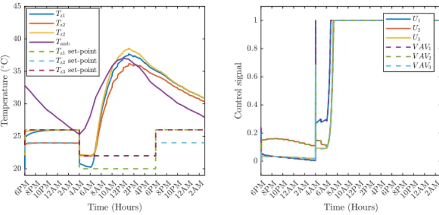
2.6 System simulation results of the zones temperatures and the VAV boxes control signals under normal operation. . . 42
2.7 System simulation results of the tank, AHU output air, and coil return water temperatures and the valve control signal under normal operation. 42 2.8 Block diagram of a healthy actuation system. . . 43
2.9 Block diagram of an actuation system subjected to actuator fault. . . 43
2.10 The relation between the flow rate percentage and the percentage of damper position (or valve opening). . . 44
2.11 System simulation results of the zones temperatures and the VAV boxes control signals under fault in VAV 1 damper. . . 45
2.12 System simulation results of the tank, AHU output air, and coil return water temperatures and the valve control signal under fault in VAV 1 damper. . . 46
2.13 System simulation results of the zones temperatures and the VAV boxes control signals under fault in the water valve. . . 46 2.14 System simulation results of the tank, AHU output air, and coil return
water temperatures and the valve control signal under fault water valve. . 46 3.1 Diagram of AANN, xi’s are the network inputs, yi’s are the network
outputs,n is the number of inputs/outputs,k is the number of nodes in the mapping/de-mapping layers, and f is the number of nodes in the bottleneck layer. . . 53 3.2 The average recovery rate and the average deviation rate for different
bias faults in sensor error correction performance of the AANN onTz1
andTz2 sensors data. . . 60
3.3 The average recovery rate and the average deviation rate for different bias faults in sensor error correction performance of the AANN onTz3
andTtsensors data. . . 60
3.4 The average recovery rate and the average deviation rate for different bias faults in sensor error correction performance of the AANN onTao
andTwosensors data. . . 61
3.5 The missing, the corrected, and the healthy sensors data of the AANN due to a single complete sensor failure for each of the six sensors. . . 62 3.6 The noisy and the filtered sensors data in noise reduction performance
of the AANN on the six sensors data. . . 64 3.7 Inaccurate and accurate sensors data in sensors inaccuracy correction
3.8 Diagram of sensor fault diagnosis scheme using AANN givenq is the number of control signals andk is the number of sensors. . . 66 3.9 The percentage of the true positive rate under single bias sensor fault
with different severity levels. . . 68 3.10 The average percentage of the false positive rate of the healthy sensors
under single bias sensor fault with different severity levels. . . 69 3.11 Single drift fault of 0.6◦C/h inTz1 sensor. (a) Faulty sensor residual.
(b) and (c) Residuals of the fault-free sensors. . . 70 3.12 Single drift fault of 0.3◦C/h inTz2 sensor. (a) Faulty sensor residual.
(b) and (c) Residuals of the fault-free sensors. . . 70 3.13 Single bias fault of 3◦C in Tz3 sensor. (a) Faulty sensor residual. (b)
and (c) Residuals of the fault-free sensors. . . 71 3.14 Single bias fault of 5◦CinTt sensor. (a) Faulty sensor residual. (b) and
(c) Residuals of the fault-free sensors. . . 71 3.15 Multiple drift faults of 0.5◦C/hand 0.9◦C/hinTz1andTtsensors. (a)
Faulty sensors residuals. (b) and (c) Residuals of the fault-free sensors. . 72 3.16 Multiple bias faults of 7◦Cand 4◦CinTz3andTwosensors. (a) Faulty
sensors residuals. (b) Residuals of the fault-free sensors. . . 73 3.17 Multiple drift and bias faults of 0.5 ◦C/h, 0.7 ◦C/h, and 4 ◦C in Tao,
Tz2, andTt sensors. (a) Faulty sensors residuals. (b) and (c) Residuals
of the fault-free sensors. . . 73 3.18 The missing, the healthy, and the corrected sensors data of the AANN
3.19 (a) Output of AANN and PCA models due to a single drift fault of 0.5◦C/hinTz2 sensor. (b) The AANN residual of the faulty sensor. (c)
The Squared Prediction Error (SPE) of the PCA output. . . 75
3.20 AANN-based method residuals of the fault-free sensors due to a single drift fault of 0.5◦C/hinTz2sensor. . . 75
3.21 The Q-contribution plot of the PCA model due to a single drift fault of 0.5◦C/hinTz2sensor. . . 75
4.1 Typical Convolutional Neural Network architecture. . . 82
4.2 Convolution layer operation. (a) The sliding of the convolution win-dow (kernel) over the input to compute the output. (b) The convolution mathematical operation (valid convolution). . . 83
4.3 Illustration of outputs of the Convolutional Neural Network layers. . . . 83
4.4 Max and average pooling operation withM = 4 andP = 2. . . 85
4.5 Flattening convolution layer (and pooling layer) output before feeding it in to the FC layers. . . 86
4.6 Under-fitting and over-fitting problems [2]. . . 90
4.7 Dropout operation [3]. . . 91
4.8 7-fold cross validation. . . 94
4.9 The CNN-based HVAC system actuator fault diagnosis method frame-work. . . 95
4.10 Reshaping the 11 system’s 1-dimensional data samples into 3D config-uration of size 3×4×3. . . 95
4.11 Potential network architectures ranging from shallow and thin (left) to deep and wide (right). . . 96
4.12 FD Model-1 using a multi-class CNN. . . 97
4.13 FD Model-2 consisting of CNN 1 to determine the system health state and CNN 2 to isolate the fault source. . . 98
4.14 FD Model-3 consisting of 5 two-class CNNs for each class of the sys-tem state. . . 98
4.15 FD Model-4 consisting of 5 two-class CNNs for each class of the sys-tem state while the last 4 CNNs share the same convolution layer. . . 99
4.16 CNN-S9-5C-2 structure. . . 102
4.17 CNN-S5-4C-5 structure. . . 103
4.18 Architecture of the CNN with best performance for Model-3. . . 107
4.19 Architecture of the CNN with best performance for Model-4. . . 108
4.20 CNN-based diagnosis method performance due to stuck F-VAV1-High fault at 100% open position at the beginning of the day. (a) Zone 1 temperature. (b) CNNs outputs. . . 111
4.21 CNN-based diagnosis method performance due to stuck F-VAV2-Hight fault at 100% closed position at night. (a) Zone 2 temperature. (b) CNNs outputs. . . 111
4.22 CNN-based diagnosis method performance due to F-VAV3-High fault at 100% closed position at night. (a) Zone 3 temperature. (b) CNNs outputs. . . 111
4.23 CNN-based diagnosis method performance due to F-Valve-High fault at 100% closed position. (a) Tank temperature. (b) CNNs outputs. . . 111
4.24 CNN-based diagnosis method performance due to stuck F-VAV1-Low fault at 18% open position. (a) Zone 1 temperature. (b) CNNs outputs. . 112
4.25 CNN-based diagnosis method performance due to stuck F-VAV2-Low fault at 56% open position. (a) Zone 2 temperature. (b) CNNs outputs. . 112
LIST OF ABBREVIATIONS
AANN Auto-Associative Neural Network
ACC Accuracy
Adam Adaptive Moment Estimation AHU Air Handling Unit
ANN Artificial Neural Network ARMAX Autoregressive Moving Average ARX Autoregressive Exogenous BBN Bayesian Belief Network
BMS Building Management and Control Systems
BN Batch Normalization
BPNN Back-Propagation Neural Network BWR Boiling Water Reactor
CAV Constant Air Volume
CHMM Coupled Hidden Markov Model CNN Convolutional Neural Network COP Coefficient of Performance CUSUM Cumulative Sum Control Chart
CWTS Continuous Wavelet Transform Scalogram DAT Discharge Air Temperature
DBN Deep Belief Network DFT Discrete Fourier Transform
DWT Discrete Wavelet Transform
EA Exhaust Air
EKF Extended Kalman Filter
EWMA Exponentially Weighted Moving Average FC Fully Connected (or Fully Closed)
FO Fully Open
FD Fault Diagnosis
FN False Negatives
FNR False Negatives Rate
FP False Positives
FPR False Positives Rate
GA Genetic Algorithm
GD Gradient Decedent
GLRT Generalized Likelihood Ratio Test
GP Gaussian Process
HMM Hidden Markov Model
HVAC Heating, Ventilation, and Air Conditioning ICA Independent Component Analysis
JAA Joint Angle Analysis
KF Kalman Filters
KPCA Kernel Principal Component Analysis LDA Linear Discriminant Analysis
LSFD Local Sensor Fault Diagnosis LSPF Local Search Particle Filter
LSSVM Least Square Support Vector Machine MCC Matthews Correlation Coefficient MMC Modular Multilevel Converter MOC Multi-Objective Clustering
MOC-RCE Multi-Objective Clustering Rapid Centroid Estimation NLPCA Nonlinear Principle Component Analysis
NN Neural Network
NPCA Nonlinear Principle Component Analysis
OA Outside Air
OLAD Discrete-Time On-Line Approximator
OPTICS Ordering Points To Identify The Clustering Structure PCA Principal Component Analysis
PF Particle Filter
PID Proportional Integral Derivative PIs Performance Indices
PLS Partial Least Squares
PO Partially Open
PPCA Probabilistic Principal Component Analysis PPV Positive Predictive Value
RA Return Air
RBF Radius Basis Function RCA Refrigerant Charge Amount RCE Rapid Centroid Optimization REC-ACC Reconstruction Accuracy
ReLu Rectified Linear Unit RNL Reduced Noise Level SEMs Spectral Energy Maps SFD Sensor Fault Diagnosis
SG Satizky-Golay
SGDM Stochastic Gradient Descent with Momentum SPC Statistical Process Control
SPE Squared Prediction Error SVM Support Vector Machine Tanh Hyperbolic Tangent
TFDK Tree-Structured Fault Dependence Kernel
TN True Negatives
TNR True Negatives Rate
TP True Positives
TPR True Positives Rate
TRNSYS Transient System Analysis
TV Total Variation
UKF Unscented Kalman Filter UPF Unscented Particle Filter VAV Variable Air Volume
VAVC Variable Air Volume Conditioning VRF Variable Refrigerant Flow
Chapter 1:
INTRODUCTION
Globally, the buildings sector accounts for about 40% of the energy consumption and more than 55% of the electricity demand [4]. Specifically, the Heating, Ventilation, and Air Conditioning (HVAC) system is one of the major and extensively operated components of buildings for providing healthy and comfortable indoor conditions and it is responsible alone for 40% of the final building’s energy usage [5]. Its main objective is to maintain the thermal comfort of occupants with minimum energy usage. This energy demand continues to rise, driven by the improved access to energy, the greater use of energy-consuming devices, and the rapid growth in the global building sector.
1.1
HVAC System Description
A typical HVAC system in buildings is composed of an air ventilation system, an Air Handling Unit (AHU), and a coil fluid chiller/heater system connected with ducts, air chambers, and pipes as illustrated in Fig.1.1. It is equipped with temperature, humidity, pressure, and flow sensors for monitoring and control purposes as well as fans, pumps, valves, dampers, and filters.
It is concerned with three main processes which are, heating and cooling related to controlling the thermal energy within the control space, humidifying and dehumidifying concerning the control of the amount of moisture in the air, and finally ventilation, filtration, and circulation of air [6].
AHU Conditioned Space Return Air Filter Supply Air Outside Air Damper Exhaust Air Damper Return Air Damper Cooling coil Heating coil Humidifier Fluid Chiller/Heater
Figure 1.1: Diagram of a typical HVAC system.
1.1.1 Air Ventilation System
The air ventilation system is responsible for the air exchange between the condi-tioned space and the outdoor environment. Mainly, the ventilation system aims to dilute the gaseous contaminants in the air and to maintain an acceptable indoor air quality in terms of freshness. However, based on the ventilation rate, in some cases it is used for maintaining the conditioned space temperature and humidity. For example, exchanging hot indoor air with cooler air, and exhausting moist air for drier air from the outside environment. Typically, in HVAC systems in commercial and institutional buildings the ratio of ventilation air to indoor air varies from 15% to 25% of the outside air [6].
1.1.2 Air-Handling Unit
The air-handling unit is responsible for bringing the space air of the conditioned space of interest to desired setpoints. Generally, its main components are the cooling coil for the cooling and dehumidification of air, the heating coil for heating, the
humidi-fier, and the air filter. All or some of those components may exist in AHUs based on the building’s requirements and the type of application. AHUs can be classified into two types in terms of the air conditioning method as constant air volume (CAV) and vari-able air volume (VAV) as illustrated in Figures 1.2 and 1.3. In CAV, the air is supplied to the conditioned space at a constant flow rate and variable temperature according to conditioning requirement. However, an AHU with VAV supplies air of a constant tem-perature that is sufficient to meet the maximum thermal load in the conditioned space and a variable air flow rate controlled to meet the desired setpoints.
The air-handling unit is one of the most extensively operated equipment in HVAC systems and hence it contributes to a significant portion of the total energy consumption in buildings. It requires follow-up maintenance closely and it is subjected to malfunc-tion and failure due to multiple factors such as poor system integramalfunc-tion, equipment failure, etc. Supply Air Conditioned Space 1 Conditioned Space 2 Variable air volume damper
Supply Air Conditioned Space 1 Conditioned Space 2 Reheat coils
Figure 1.3: A CAV system for a two-zone HVAC system.
1.1.3 Fluid Chiller/Heater System
The fluid chiller/heater system is dedicated to adjusting the fluid temperature before supplying it to the AHU coils. Chiller plants account for a considerable portion of the energy consumption of HVAC systems. That is, under faulty operation -due to performance degradation or malfunction-, a significant amount of energy is wasted [7].
1.2
Objective of HVAC Systems
The HVAC system is desired to provide an acceptable indoor environment with optimum cost and energy usage solutions. The objective of HVAC systems can be described in terms of the following factors: air quality, thermal comfort, safety, and system’s reliability and efficiency [6].
1.2.1 Air Quality
The air quality inside buildings is an important factor affecting the health of the occupants. One of the primary objectives of the HVAC system is maintaining the min-imum essential air quality measures by supplying clean, odor-free outdoor air to the
excessive moisture, gases, and other airborne pollutants generated must be removed from the indoor air.
1.2.2 Thermal Comfort
The thermal comfort can be defined as the measure of satisfaction of occupants with the indoor environment. It is directly affecting their health and productivity. Thermal comfort can be considered subjective due to some influencing factors such as the activ-ity level, clothing, and individual preferences of occupants. However, there are main factors directly related to the management of the HVAC system operation which are the supply air temperature and speed, the radiant heat, and the humidity level. It is required that the indoor air temperature and motion are closely and simultaneously controlled as to maintain the desired and acceptable temperature overly and without causing draft discomfort or a stuffy environment.
1.2.3 Safety
The assurance of occupants’ safety is essential. The HVAC system’s equipment may be potential and serious hazard sources in case of failure or malfunction. For ex-ample, a heating equipment can cause a potential fire hazard. Improper air distribution in case of fire occurrence can result in spreading the fire in the building [8]. Moreover, a malfunction in the HVAC system components and sensors can interfere in safety and evacuation procedures, Hence, precautions and proper management of HVAC systems are necessary to prevent such incidents and to employ the system in assisting safety assurance operation.
1.2.4 Reliability and Efficiency
The reliability and efficiency of the HVAC system operation are important charac-teristics. The HVAC equipment is desired to operate healthily and normally on the long run with minimal maintenance requirement as to lower the repair costs. Moreover, the HVAC systems’ energy consumption must be optimum, and this is achieved by proper HVAC system design based on the building’s type, size, etc., and by proper control and monitoring of the system’s operation.
1.3
Thesis Motivation
As mentioned previously, HVAC systems are major components of buildings for providing healthy, acceptable quality, and comfortable indoor conditions for occupants. Their main aim is to provide a safe and comfortable indoor environment for occupants while maintaining an efficient and reliable performance. However, they are subjected to failure that would affect their functionality and performance. For example, faults in HVAC systems can result in providing lower air quality, which would jeopardize the safety and health of occupants.
In addition, they would reduce energy efficiency by the faulty and unnecessary in-crease in energy usage. Moreover, faults can interfere in the execution of safety supervi-sion scheme (e.g. building evacuation) and affect their effectiveness and correctness by resulting in executing crucial tasks based on faulty decisions [9]. Nevertheless, faults in the HVAC system cause components’ wear which results in shortening their lifetime and increasing the maintenance cost.
Hence, Fault Diagnosis (FD) in HVAC systems becomes very essential in order to achieve the best system performance with minimum costs. It is important to develop effective and robust FD techniques for HVAC systems in order to identify the fault occurrence and source.
1.4
Fault Diagnosis Methods of HVAC Systems
Faults are defined as undesired deviations of the characteristic properties of the sys-tem from the standard conditions. They can be classified as sensor faults, actuator faults, and process faults (components or parameter faults). Faults may result in interruption of control action of the process controller, substantial measurement error, changing the dynamic properties of the system leading ultimately to degradation in the performance of the system or its breakdown and damage [10]. Fault diagnosis methodologies can be generally classified as: model-based methods, signal-based methods, knowledge-based methods, and hybrid methods as categorized in [10].
1.4.1 Model-based Methods
In model-based methods, the knowledge of the process models is required, which can be obtained using the physical principles or system’s parameters identification ap-proaches. Fault diagnosis algorithms are developed based on those models to moni-tor the consistency between the measured outputs of the real systems and the model-predicted outputs. They can be defined as follows:
1) The observer-based approach, in which the actual data of the system’s states of interest is compared with the estimated ones by the observer. The generated error resid-uals are used to diagnose faults according to the detection thresholds. For deterministic
systems, Luenberger observers can be used while Kalman Filters (KFs) are employed when the system is subjected to noise that can affect the fault diagnosis procedure [11]. 2) Parity relation approach where the residuals are generated by checking the parity between the estimated and the actual system measurements of the concerned outputs.
3) Parameter estimation using system identification methods (e.g., least square error, etc.) such that it is assumed that the faults are reflected on the parameters of the system. The fault diagnosis depends on the online estimation of the parameters which are then compared with the nominal ones under fault-free system operation.
1.4.2 Knowledge-based Methods
They require a considerable amount of historical data of the concerned system on which artificial intelligence techniques are applied to extract knowledge -quantitatively or qualitatively- about the system. The behavior of the actual system is compared against the knowledge-based model to produce the fault diagnosis decision [12]. They are defined as the following:
1) Expert system-based methods: They are rule-based approaches that are built based on human expertise. The evaluation is performed on the online monitored data based on the deduced rules. Even though they are easy to develop and use once the rules are at available, they are difficult to generalize and expand to variants of the system, e.g. in terms of type, size, etc.
2) Data-driven methods, which can be classified based on their analysis approach as statistical or non-statistical. The common statistical analysis used are Principal Com-ponent Analysis (PCA), Partial Least Squares (PLS), Independent ComCom-ponent Analysis (ICA), Support Vector Machine (SVM), and clustering analysis. On the other hand, the
non-statistical analysis-based data-driven fault diagnosis algorithms are Neural Net-works (NNs) and fuzzy logic.
The data-driven FD approaches can be developed in supervised-learning, and unsupervised-learning manners. In the supervised-unsupervised-learning fault diagnosis methods, the knowledge
of both the faulty and fault-free system data is required to build the model while in the unsupervised-learning, the knowledge is extracted from the unlabeled historical data of the system.
1.4.3 Signal-based Methods
Signal-based fault diagnosis methods work under the assumption that the faults can be linked to the measured signals features and patterns. Signals analysis such as fre-quency and spectral analysis are employed provided that the faults are reflected on the spectral features of the signals. In addition, signals measurements such as energy, cur-rent, etc. can be used as certain faults indicators.
The difference between the signal-based methods and data-driven methods is that the latter is based on analyzing an amount of historical data to deduce useful information about the behavior of the system of interest. However, the signals-based approaches do not require large amount of data but rather utilize the real-time signal measurements and employ signal processing techniques.
1.4.4 Hybrid Methods
In the hybrid method, a combination of their previously discussed methods is de-veloped to make use of the distinctive advantages and strengths and to compensate for their limitations. Examples of hybrid methods are the use of parameter estimation with
1.4.5 Characteristics of Fault Diagnosis Methods
There are a number of important features that are desired in the fault diagnosis methods which are the response time, efficiency, reliability, isolability, robustness, and low computation and modeling requirements [10]. Quick fault diagnosis is desired to prevent escalating the impact of the fault on the system components and to maintain the efficiency and reliability of the system. Moreover, the diagnostic method should be able to identify the location of the faults as well as to be robust to measurement noise and modeling uncertainty to avoid false fault alarms. The modeling and computational re-quirements of the fault diagnosis strategy are required to be minimal for high feasibility and ease of implementation of the method on real-life systems. In addition, high scala-bility of the fault diagnosis method is preferred in order to easily adapt it for variants of the system.
1.5
Literature Review on Fault Diagnosis in HVAC Systems
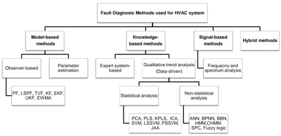
Fault diagnosis of HVAC systems is essential to provide preventive maintenance and to maintain the system’s reliability and efficiency. Given the literature, most of the FD methods in HVAC systems are studied at the sub-system level (i.e., AHU, chiller system, etc.). The state-of-the-art diagnosis approaches used for the HVAC systems found in the literature are summarized in Fig.1.4.
Fault Diagnosis Methods used for HVAC system Model-based methods Observer-based PF, LSPF, TVF, KF, EKF, UKF, EWMA Parameter estimation Knowledge-based methods Expert system-based
Qualitative trend analysis (Data-driven) Statistical analysis PCA, PLS, KPLS, ICA, SVM, LSSVM, PSSVM, JAA Non-statistical analysis ANN, BPNN, BBN, HMM,CHMM, SPC, Fuzzy logic Signal-based methods Frequecny and spectrum analysis Hybrid methods
Figure 1.4: Summary of the fault diagnosis methods used for HVAC systems.
1.5.1 Model-based Methods
Model-based methods are used in developing fault diagnosis algorithms for HVAC system components, such as AHUs, chiller plants, etc. as summarized in Table 1.1. Authors in [13] and [14] present an unknown residual generation observer-based fault diagnosis algorithm for stuck dampers faults in VAV boxes in AHUs. The FD method is validated using MATLAB/Simulink on a 4-zone HVAC system. In [15], a nonlinear joint state-parameter observer-based method for damper position estimation in VAV boxes is proposed. It is implemented for stuck damper fault diagnosis such that the fault is reflected on the ratio of the air flow to each zone provided that a constant nominal flow rate supplied by the supply air fan. The method is tested using MATLAB on a simple two-zone HVAC system.
In [16], a model-based FD approach is proposed employing two state observers to perform fault detection and fault isolation. The first observer is comprised of discrete-time on-line approximator (OLAD) and a robust term while the other one includes the models of faults. The method is tested using simulation and the type of faults considered
temperature, and leakage from conditioned space (or insulation degradation) emulated by the change in the zone air temperature.
In [17] and [18], a model-based fault diagnostic approach is presented for valve actuator faults in discharge air temperature (DAT) system using a combination of state and parameter estimation. In [18], a dual Extended Kalman Filter (EKF) is used while in [17], a joint Unscented Kalman Filter (UKF) is used for actuator faults and both are compatible with the nonlinearity in the HVAC system model. The actuator fault is modeled as a multiplicative fault and the FD methods are validated using MAT-LAB/Simulink.
In [19], a novel model-based on-line robust fault diagnostic approach is proposed based on Unscented Kalman Filtering and back-smoothing algorithm for typical faults in the chiller plants. The types of faults considered are process faults represented by reduced efficiency of components such as compressor which might result in excessive energy consumption and degrades its performance, and valve actuator faults resulting in reduced air flow rate. The FD strategy is tested and validated using simulation tools. In [20] and [21], an interactive multi-model augmented FD approach based on unscented Kalman Filter is developed for valve actuator faults and the fault modes generated by the possible perturbations in HVAC systems.
A model-based fault diagnostic algorithm is developed in [22] and [9] for sensor faults and in [23] for actuator faults in complex multi-zone HVAC systems on a dis-tributed framework. Each subsystem is equipped with a dedicated local sensor as a fault diagnosis (LSFD) agent. The distributed sensor fault detection is conducted us-ing robust analytical redundancy relations of estimation-based residuals and adaptive thresholds. Both sensor and actuator faults are examined for constant bias or offset
faults. The method is validated using simulation for faults in the temperature sensors and water valves.
The automated strategy proposed in [24] and [25] utilizes a Total Variation (TV) filter with an enhanced Particle Filter (PF) for faults detection in heat exchangers. The TV filter is used for transient occurrence detection and the Local Search Particle Filter (LSPF) is used for degradation tracking. The types of faults evaluated in the paper are condenser fouling, refrigerant leakage, non-condensable, and reduced water flow rate. The validation of the algorithm is carried out using simulation tools and experimental chiller faults data for different severity level of the four types of the fault.
Table 1.1: Model-based FD methods developed for HVAC systems.
Ref. Fault type Approach
[22], [9] Sensor - Overall system Observer [23] Sensor and actuator - Overall system Observer
[16] Process - AHU Observer
[20], [21] Actuator - DAT system UKF
[17] Actuator - DAT system Joint UKF
[18] Actuator - DAT system Dual EKF
[14], [13] Actuator - VAV boxes Observer
[15] Actuator - VAV boxes Parameter estimation
[24], [25] Process and actuator - Heat exchangers TVF, LSPF, and KF [19] Process and actuator - Chiller system UKF and BSA
1.5.2 Signal-based Methods
There are a few signal-based fault diagnosis methods for the HVAC system as sum-marized in Table 1.2. In [26], an electrical measurement-based approach is presented for fault detection of airflow blockage faults in AHUs and estimation of insufficient airflow employing induction machine diagnostic work. While in [27], a signal-based FD method is proposed for airflow blockage and unbalanced load of fan faults in the AHU based on frequency spectrum analysis. In addition, a fault detection strategy is presented in [28] for valves in AHUs employing frequency and spectral analysis as well. Table 1.2: Signal-based FD methods developed for HVAC systems.
Ref. Fault type Approach
[27] Sensor and process - AHU Freq. spectrum analysis [28] Actuator - AHU Freq. and spectral analysis [26] Sensor and process - AHU Signal processing and analysis
1.5.3 Data-driven Methods
The majority of the fault diagnosis approaches proposed for the HVAC systems are data-driven given the high complexity of the system as well as the fact that modern buildings are equipped with building management and control systems (BMS) where records of the HVAC system data can be obtained and used in the development of the diagnostic strategies. The different data-driven methods used for HVAC system fault diagnosis that are found in the literature are summarized in Table 1.3.
In [29], a sensor FD algorithm for the AHU is discussed employing a Machine Learning technique systematically based on analyzing the system’s behavior and
com-paring it against faulty conditions described by a set of behavioral patterns. Common faults are considered which are stuck damper/valve, coil fouling, and damper leakage. A novel fault diagnostic architecture for variable refrigerant flow (VRF) in AHUs is pro-posed in [30] based on Bayesian Belief Network (BBN) employing expert rule-based technique. The type of evaluated faults are refrigerant under-change and overcharge. The diagnosis method is tested using a practical VRF system under different cooling modes and operation conditions.
In [31], an ICA-BPNN-based fault diagnostic method is presented for refrigerant charge faults in the VRF systems combining Independent Component Analysis (ICA) and Back-Propagation Neural Network (BPNN) methods. The ICA is used for fault de-tection and the BPNN is employed to develop the fault diagnosis model. A data-driven fault diagnostic strategy for refrigerant charge amount (RCA) faults in the VRF systems is proposed in [32] by combining SVM mRMR-based feature selection and Wavelet De-noising (WD) algorithm. In addition, an enhanced Back-Propagation Neural Network (BPNN). While in [33], a fault diagnosis strategy is proposed for refrigerant charge amount faults -overcharge or undercharge- in the VRF systems utilizing PCA and dual ANN model.
In [34], an improved Decision Tree (DT)-based diagnostic approach is proposed for the VRF system. It combines a data-driven model and a virtual sensor-based fault indicator for faults detection. In [35], a fault diagnosis strategy is presented based on PCA and pattern matching using two factors for characterization of the similarity degree between the historical data and real-time data. While in [36] a FD method is proposed by integrating D-matrices and PCA, and in [37] an enhanced and novel sensor fault diagnosis strategy is presented using the Satizky-Golay (SG) and the PCA methods for
the VRF system, namely SG-PCA method. The SG algorithm is used for smoothing the data based on the least-squares polynomial approximation and the PCA model is trained for fault diagnosis using the smoothed data. In [38], an improved PCA-based with Joint Angle Analysis (JAA) approach is proposed for sensor faults diagnosis in the VAV system considering both fixed bias and drifting faults.
A novel HVAC fan machinery fault diagnosis approach is developed in [39] and [40] by combining Kernel Principal Component Analysis (KPCA) and Least Square Support Vector Machine (LSSVM). In [41], an unsupervised diagnostic strategy is presented employing cluster analysis for AHU sensor fault detection assuming that the faulty data is spatially and temporally separated from the normal data. The recorded history data of the system is pre-processed using PCA for dimension reduction. The clustering algorithm ordering points to identify the clustering structure (OPTICS) is used for data separation and type identification. The sensor faults are modeled as constant offset faults with different severity levels and the FD method is validated using TRNSYS simulation tool. In [42], a dual Neural Network (NN) strategy is proposed for AHU sensor faults detection in which the basic and auxiliary neural networks are developed then combined through allocating the weighting factors of the two neural networks using PCA. Two types of sensor faults are examined which are positive/negative fixed offset and drifting bias in addition to the case of complete sensor failure and a stuck water valve actuator fault. The FD method is validated using TRNSYS simulation tool. While in [43], a robust fault diagnosis method is developed by combining neural networks and subtractive clustering analysis for the same fault types as in [42]. The dual neural networks are used for fault detection and the subtractive clustering analysis is employed for fault diagnosis through adaptive classification of the faults’ sources.
In [44], a FD method is presented employing SVM for common faults in the variable air volume conditioning (VAVC) systems in the HVAC system. The evaluated sensor and actuator faults are stuck chilled water valve, stuck VAV box damper fixed bias temperature sensor, and stuck recirculation damper. The FD strategy is tested using MATLAB/Simulink simulation model. While in [45], a novel fault diagnostic approach is developed based on the combination of Gaussian Process (GP) and SVM algorithms for AHUs. The GP algorithm is used to provide a probabilistic model to estimate the AHUs measurements as a function the external variables; time, occupancy, and the ambient temperature. Prediction error and variance are computed then its ratio is used in the SVM algorithm to develop the data-driven model that can be used to detect the faults. It is tested using TRNSYS simulation tool for a 46-zone building.
In [46], a self-adaptive sensor FD approach for an AHU is presented. It consists of two FD models, one for the AHU control loop including two Back-Propagation Neu-ral Networks (BPNNs), and the other model is developed using both wavelet analysis method - for measurement data processing - and Elman neural network for sensor fault identification. The considered sensor faults are fixed bias, drifting bias, and complete sensor failure and the proposed FD strategy is validated using simulation. In [47] and [48], a dual FD approach is presented for VAV boxes in the AHU employing both ANN and fuzzy logic. The latter is utilized for fault detection, and the ANN is used for fault identification. The typical faults in AHU are examined which are damper fault, coil water valve error, sensor offset fault, and the fan fault. The validation of the FD method is carried out by simulating a multi-zone system in MATLAB/Simulink.
In addition, an automated FD strategy for sensors failure in the AHU is proposed in [49] employing Radius Basis Function (RBF) network and a combination of Genetic
Algorithm (GA) and pseudo-inverse matrix algorithm for Gaussian function parameters selection. A Deep Bayesian Networks (DBNs)-based approach is proposed in [50] and [51] for the diagnosis of common faults in AHUs. It uses the diagnostic information about the HVAC system in an information fusion way utilizing fault patterns recorded from multiple identical systems. A semi-supervised fault diagnostic algorithm is devel-oped in [52] and [53] based on PCA statistical model along with a reconstruction-based approach. The PCA model is used for identifying healthy and faulty operation, and the reconstruction-based contribution approach is used for variables isolation, and decision tables for fault diagnosis.
In [54], a FD strategy is presented for chiller systems using Bayesian network clas-sifier with probabilistic boundary in order to eliminate the problem of high false alarm rate. Typical faults in chiller systems are considered in the proposed FD method which are, the reduced condenser water flow, the reduced evaporator water flow, the refrigerant leakage, the refrigerant overcharge, the condenser fouling, the non-condensable gas in the refrigerant, and the excess oil for different severity levels and operating conditions. Additionally, a novel on-line FD method is developed in [55] based on Tree-structured Fault Dependence Kernel (TFDK) method for fault classification for the same types of faults as in [54]. While in [56], a two-stage fault diagnosis strategy is proposed adopting Linear Discriminant Dnalysis (LDA) for data dimension reduction and a distance-based classifier for the common faults in chiller systems.
In [57] and [58], the development of fault diagnosis approach is discussed using neural networks and statistical tools for HVAC chillers. The GLRT is used for faults detection while SVM, PCA, and PLS, are used for faults isolation. In addition, PLS is employed for faults severity estimation and chiller system modeling. Moreover, in
[57] an algorithm for optimal sensor suite selection for maximizing diagnosability is proposed. The same fault diagnosis strategy developed in [49] is proposed and applied for refrigeration units in the HVAC system in [59].
In [60], a fault diagnostic strategy using Artificial Immune Recognition System (AIRS) is proposed based on history and simulation classified system data for 13 com-mon faults in the HVAC system. The method is validated using TRNSYS for a 10-zone building equipped with a full HVAC system. Where in [61], an online fault diagnosis framework is proposed based on the lattice-valued fuzzy automate such that the sys-tem is modeled as a fuzzy discrete event syssys-tem. An online fault detection algorithm is presented in [62] utilizing Machine Learning techniques and HMM model such that the probabilistic relationships among variables of interest are analyzed and encoded. In addition, a sensor fault detection algorithm is proposed in [63] in which a combination of Probabilistic Principal Component Analysis (PPCA) models are used.
In [64], a FD approach is developed for HVAC systems employing Multi-Objective Clustering Rapid Centroid Estimation (MOC-RCE) technique which combines Rapid Centroid Optimization (RCE) algorithm and the Multi-Objective Clustering (MOC) paradigm. A clustering-based distributed sensor fault diagnosis algorithm is presented in [65] for Wireless Sensor Networks (WSN) monitoring HVAC systems, allowing the diagnosis of multiple sensor faults under the presence of disturbances and uncertainties. In addition, in [66] a fault detection method is presented employing spectral cluster-ing and PCA for better root cause fault detection and reduction of false alarms. Authors in [67] describe the application of a robust dual fault detection approach for HVAC sys-tems under real-time working conditions using online SVM classifier combined with an ANN model. A data-driven FD method is developed in [68] combining BBN and
rule-based analysis for fault diagnosis in AHUs. The types of faults examined are process faults such as fouling, control signal error, sensor bias faults, and actuator faults, such as a stuck valve, stuck damper, etc.
In terms of the knowledge-based methods, an automated expert rule-based FD method is described in [69] for common faults in VAV boxes using mass and energy balance equations of various subsystems of the AHU. In addition, authors in [70] developed a novel semantic knowledge-based fault detection approach utilizing physical system knowledge encoded in a semantic graph to identify potential causes of faults.
Table 1.3: Data-driven FD methods developed for HVAC systems.
Ref. Fault type Approach
[45] Sensor and process - AHU SVM
[71] Process - VRF BPNN and ANN
[33] Process - VRF PCA and ANN
[42] Sensor and actuator - AHU NN and PCA
[43] Sensor and actuator - AHU NN and subtractive clustering
[46] Sensor - AHU BPNN and NN
[38] Sensor - VAV boxes PCA and JAA
[54] Process - Chiller system Bayesian network
[55] Process - Chiller system Tree-structured TFDK method
[35]
Sensor, process, and actuator -AHU
PCA and pattern matching
[41] Sensor - AHU PCA and clustering analysis
[29] Process and actuator - AHU Bayesian network
[57], [58] Process - Chiller system PCA, NN, SVM, PLC, GLRT [52] Process - Chiller system PCA
[53] Process - Chiller system PCA and RBC
[39], [40] Process - AHU KPCA and LSSVM
[70] Process and actuator - AHU Expert-rule
Ref. Fault type Approach
[44]
Sensor and Actuator - VAV boxes
SVM
[64] Process and actuator - AHU MOC-REC clustering [49] Sensor and process - AHU GA and RBF methods [59] Process - Refrigeration unit GA and RBF methods
[47], [48]
Sensor, process and actuator -VAV boxes
ANN and Fuzzy logic
[67] Process -AHU SVM and ANN
[61]
Sensor, process, and actuator -Overall system
Fuzzy logic
[36]
Sensor, process, and actuator -AHU
PCA and D-matrices
[62]
Sensor, process, and actuator -AHU
DBN, HMM, and clustering analysis
[50], [51]
Sensor, process, and actuator -AHU
Bayesian networks
[37] Sensor - VRF SG-PCA method
[56] Process - chiller system LDC and distance classifier
[30] Process - VRF BBN
[31] Process - VRF ICA and BPNN
Ref. Fault type Approach
[63] Sensor - Overall system Parity relation and PCA
[34] Process - VRF Decision tree and VR-FI-based
[65] Sensor - Overall system Distributed clustering-based
[68]
Sensor, process, and actuator -AHU
BBN and rule-based analysis
1.5.4 Hybrid Methods
Several applications of hybrid fault diagnosis strategies for HVAC systems com-bining model-based and data-driven methods are proposed by researchers. Table 1.4 summaries the hybrid FD methods used for HVAC systems in the literature. In [72], SVM is applied to the model parameters that are found recursively by an autoregressive time series model with exogenous variables (ARX). The types of faults considered in the paper are actuator faults and process faults which are a stuck exhaust air damper, a stuck speed return fan, complete failure of return fan, an unstable cooling coil valve control, a stuck outside air damper (fully open or fully closed), a stuck cooling coil valve (partially open, or fully open or fully closed ), outside air damper leak, and duct leak.
A hybrid FD strategy is proposed in [73] for cooling coil faults using Unscented Kalman Filter and Statistical Process Control (SPC). The types of faults tested are pro-cess faults due to fouling and accumulation of dust particles. The diagnosis method is evaluated using simulation tools. Similar to [73] but on the system-level, UKF and SPC are used in [74] for robust fault detection with potentials for large-scale implementation.
In [75], a novel hybrid FD technique in the AHU is proposed considering fault propagation impacts among components. The fault diagnostic strategy combines both filtering technique - Kalman filter and Unscented Particle Filter (UPF)-, and Hidden Markov Model (HMM) which is a statistical model representing the relationships be-tween hidden states and observations. Statistical Process Control (SPC) is employed for process monitoring and control. Sixteen typical types of faults occurring in AHUs are considered including process and actuator faults which are, a stuck exhaust air damper (closed/open), a stuck outside air damper (closed/leakage), cooling coil tube fouling, dust on cooling coil fins, a stuck water valve (closed/open), duct leakage at different parts of the system (before/after supply fan), complete fans failure, and reduced fan ef-ficiency. The FD method is validated using a simple two-zone HVAC model simulated using MATLAB/Simulink.
In [76], a FD strategy is proposed for the AHU and multiple VAV boxes. The developed algorithm utilizes dynamic HMMs, UPF, and SPC for fault identification in the cooling coil, fans, and VAV boxes. The difference between [75] and [76] is that the former emphasis is on fault propagation impact while in [76], the proposed strategy highlights diagnosing faults of many VAV boxes with minimum computational effort and the algorithm used for sensor faults detection.
In [77], a robust FD strategy is presented for multiple faults in AHU by using a rule-based and residual-based Exponentially Weighted Moving Average (EWMA) con-trol chart method. EWMA is used for fault detection and the expert rule-based method is used for simultaneous multiple faults isolation in the VAV boxes. The types of faults considered are pump fault, cooling coil fouling, cooling coil valve leaking, a stuck cool-ing coil valve, coolcool-ing coil valve controller failure, filter failure, fan failure, temperature
sensor fault, pressure sensor fault, and incorrect chilled water temperature settings. It is validated using operational data of a 36-office building that is fully equipped with an automated energy management and control system.
In [78], a hybrid approach is proposed for on-line fault detection in the chiller plants. It is based on Particle Filter (PF), joint nonlinear Bayesian-based estimation, and kernel-based partial least square method. Moreover, a hybrid fault diagnostic approach is proposed in [79] combining EKF with coupled Hidden Markov Model (CHMM) in the chiller plants. The typical fault is taken into consideration which is the pipe fouling and the leakage. The fault diagnostic method is tested using EnergyPlus simulation tool for a simple two-zone building equipped with a full HVAC system.
In [80], a hybrid fault diagnostic technique is proposed in which the interdependen-cies among the different HVAC subsystems is considered and the algorithm can easily be adapted to dynamical operational conditions and different building configurations. The proposed system-level FD approach utilizes knowledge about the HVAC system’s modules interdependency, the energy and mass conservation laws, and the historical data of the system in developing the diagnostic model.
In [81], a combined system-level and sensor fault FD strategy is proposed for the HVAC systems comprising of two schemes. A system-level fault diagnosing scheme performance indices (PIs) are introduced to determine the performance status of each system as faulty or healthy. The other scheme is for bias sensor fault diagnosis using PCA. Similarly, a hybrid system-level fault diagnostic approach is proposed in [82] for the low delta-T syndrome in the AHU and heat exchanger due to performance degra-dation in complex HVAC systems. The HVAC system measurement data are processed online to generate the performance indices and the reference models are developed
offline using the regression model which are used in determining the benchmarks of the PIs. Adaptive residuals are calculated using the t-statistic approach to identify the healthy conditions of the performance indices. Additionally, in [83] a fault diagnosis method is proposed for low delta-T syndrome resulted from the cooling coil fouling in heat exchangers. The method uses defined performance indices and adaptive thresholds in order to improve the prediction uncertainty of the reference models. The proposed method is validated using simulation tool.
A novel fault diagnosis strategy is developed in [84] based on parameter estimation utilizing a recursive least-squares-based algorithm to detect faults in the HVAC system operation. A time-varying ARX/ARMAX model is formulated based on the paramet-ric model found from the recursive identification for the types of fault studied. The algorithm is tested for the common fault type occurring in different components of the HVAC system using simulation tools.
In [85], a fault detection and isolation architecture for the VAV boxes is developed based on an integrated statistical and linear model-based framework. A statistical model is developed employing PCA and joint angle analysis for determining benchmarks and a linear model-based framework is designed for FDI of multiple actuator and multiple sensor faults. Additionally, the algorithm includes a safe parking strategy for energy savings purposes. A cross-level FD technique is proposed in [86] for complex HVAC systems. It is based on energy performance monitoring of the HVAC system units, and temporal and spatial partition. Energy utilization is observed in groups and at different levels over well-defined time periods and consequently suitable thresholds are defined for the purpose of fault detection and identification. PCA is used to identify the corre-lations between system variables.
In [87], a hybrid FD method is proposed combining a rule-based classifier with signal-based CUSUM control chart for sensor faults, process faults, and actuator faults in VAV boxes. In [88], a novel FD strategy is presented based on exponentially weighted moving average charts and Shewhart charts that are compared to a breakout detection algorithm to diagnose faults in the HVAC system. In addition, the method is tested using simulation tools and artificial faults are injected and used for validation of the statistical techniques used.
Table 1.4: Hybrid FD methods developed for HVAC systems.
Ref. Fault type Approach
[84] Process - Overall system RLS and parameter estimation
[80] Process and actuator - AHU
Bayesian network and model-based method
[72] Process and actuator - AHU ARX model and SVM [75] Process and actuator - AHU KF,UPF, HMM, and SPC [76] Process and actuator - AHU UPF, HMM, and SPC [74], [89] Sensor and process - Overall system UKF and SPC
[73] Process - AHU UKF and SPC
[79] Process - Chiller system EKF and CHMM
[78] Process - Chiller system
PF, parameter estimation, and KPLS
[77]
Sensor, process, and actuator -AHU
(EWMA) control chart method and expert rule-based method
[81]
Sensor, process and actuator - Over-all system
PCA and performance indices
[82], [83] Process - AHU SPC and parameter estimation [85] Sensor and actuator - VAV boxes PCA, JAA, KF
[86] Process - Overall system Signal-based and PCA
[87]
Sensor, process, and actuator - VAV boxes
Rule-based classifier with CUSUM control chart
By reviewing the previous works on fault diagnosis in HVAC systems, limited re-search works cover sensor and actuator faults diagnosis and the matter of sensor data validation and reconciliation is not investigated thoroughly. The focus of the majority of the previous works is on the process faults occurring in the chiller system specifi-cally. This is justified given the impact of the chiller system-related faults on the HVAC system performance and efficiency. Nevertheless, we think that further research in sen-sor and actuator faults diagnosis is indispensable for the following reasons. The sensen-sors measurements are crucial for the HVAC system operation (i.e. the closed-loop control, the execution of supervision scheme, etc.) and hence the sensors data must be reliable and fault-free. In addition, the actuator faults can alter the HVAC system in terms of maintaining occupants comfort as a result of failing to fulfill the thermal load require-ment, system maintenance (i.e. ducts damage or leak due to increased pressure due to damper blockage), and potentially the energy consumption.
Most of the model-based approaches found in the literature are developed for sen-sor and actuator fault diagnosis. They can diagnose unknown faults utilizing limited knowledge about the system (i.e. the mathematical model), but they require an accu-rate, detailed, and explicit model depicting the system’s operation. Hence, the perfor-mance of the fault diagnostic algorithm depends on the model’s accuracy. This limits the scalability and adaptability of the diagnosis methods when considering larger and variants buildings. On the other hand, even though the signal-based HVAC fault diag-nosis approach does not require the system mathematical model, it is concerned with the major characteristics of the output signals for diagnosis with less attention to system dynamics resulting in potential degradation of the diagnostic approach performance in the presence of unknown disturbances.
On the other hand, the rule-based FD method requires the expert knowledge and it may perform poorly under undefined conditions by the set of the diagnosis rules. Moreover, data-driven HVAC fault diagnosis methods are commonly used as shown in the previous sections. Their main advantage is that the system’s model is not required. Hence, they better suit applications where systems models are unavailable, complicated, or challenging to derive such as complex HVAC systems but their performance is tied to the amount and quality of the training data used. More specifically, the use of Machine Learning algorithms such as PCA, SVM, neural networks, etc. in developing HVAC fault diagnosis approaches is evolving. In addition, the newly emerging field of deep learning demonstrates notable capabilities in pattern recognition and health monitoring. It has not yet been applied for HVAC system fault diagnosis, but it has a wide range of similar applications with promising performance. That is, the learning-based methods are characterized by the following features: scalability, reliability, high performance accuracy, and low false alarms rate which are the desired characteristics in the HVAC fault diagnosis system. They can be developed by making use of historical data from the building management system.
1.6
Thesis Objectives
Researchers have been investigating various solutions for fault diagnosis in the HVAC system as demonstrated by the literature survey. However, the improvements are still not keeping up with the growing sector and the increasing global demand for energy. The main objective of this work is to develop an effective fault diagnosis method as to improve the efficiency and reliability of the HVAC system that can be applied to variants of the systems and making use of the availability of system historical data from
the BMS.
This is tackled by proposing two data-driven fault diagnosis methodologies for sen-sor and actuator faults. Firstly, a sensen-sor data validation and fault diagnosis strategy is developed given that sensors measurements are crucial in the closed-loop control oper-ation of the HVAC system. It aims to promote the HVAC system operoper-ation becoming invulnerable under sensor faults and degradation. In addition, a novel and robust CNN-based actuator fault diagnosis is developed to reliably diagnose dampers and valves faults in the HVAC system with high accuracy.
1.7
Thesis Contribution
The contribution of this thesis work can be summarized as follows:
• Two data-driven fault diagnosis strategies are developed for HVAC system sen-sor and actuator fault diagnosis that do not require the knowledge of the system mathematical model and hence avoiding the complications that can arise due to modeling approximation and uncertainties. The methods are developed utiliz-ing the buildutiliz-ing’s historical data that can be obtained from the modern buildutiliz-ing management systems.
• A semi-supervised on-line sensor fault diagnosis method for HVAC systems is proposed using an Auto-Associative Neural Network (AANN) for both single and multiple faults utilizing only the healthy sensors data. Due to the network structure, the method is capable of sensor data validation in terms of replacing missing sensor measurements with the validated data, correcting inaccurate or faulty data, and filtering out measurement noise.
• The proposed AANN-based sensor data validation and fault diagnosis technique serves as an effective method to validate sensor measurements for the closed-loop control of the HVAC system to maintain its reliable performance. It can be applied for large-scale buildings with additional zones and it is expected that the performance will be improved with the increase in the HVAC system size due to a higher correlation between the inputs. The proposed AANN-based approach is suitable for applications where sensors measurements are broadly steady over the operation period which is the case with HVAC systems.
• A novel supervised on-line actuator fault diagnosis for HVAC systems using 2D Convolutional Neural Networks (CNNs) is proposed based on a data transfor-mation to obtain the 2D representation of the raw 1D measurements data of the HVAC system variables without advanced data pre-processing requirement. The CNN-based actuator fault diagnosis method demonstrates an improved perfor-mance when compared with the commonly used methods and it addresses the limitations of the past works in terms of the method’s accuracy, reliability, and precision.
1.8
Thesis Organization
The remainder of this thesis report is organized as follows. In Chapter 2, the de-tails of the building and the HVAC system under this study are presented along with the description of the simulator design using TRNSYS in Sections 2.1 and 2.2 respec-tively. The simulator details are demonstrated in Section 2.2.1 and simulation results are presented in Sections 2.2.2 and 2.2.3 for the normal operation and in case of actuator faults. In addition, in Chapter 3 the proposed sensor data validation and fault diagnosis
approach using the Auto-Associative Neural Network is described. An overview of the theory of Back-Propagation Neural Networks in provided in Section 3.1 and in Section 3.2, the theory of the Auto-Associative Neural Network is presented in addition to the details of the network training procedure and the performance evaluation metrics used. Section 3.3 presents the evaluation results and discussion of the sensor data valida-tion method while the performance of the proposed approach in sensor fault diagnosis is demonstrated in Section 3.4 and a comparison between the proposed AANN-based scheme and a PCA-based method is presented in Section 3.5. A summary is presented in Section 3.6.
In Chapter 4, a Convolutional Neural Network-based fault diagnosis scheme is de-veloped for actuator faults in HVAC systems. Section 4.1 presents the theory of the Convolutional Neural Networks and in Section 4.2 the training specification, proce-dures, and performance metrics are described. The details of the proposed diagnosis framework are explained in Section 4.3 and the evaluation results of the developed scheme are demonstrated in Section 4.4. In addition, a comparison between the convo-lutional neural network-based approach and other commonly used methods for HVAC systems fault diagnosis is conducted is Section 4.5. A summary is presented in Section 4.6. Finally, Chapter 5 provides a summary of the final conclusions of this thesis work presented in this report in addition to future work.