ROS Wrapper
for Real-Time Multi-Person
Pose Estimation
with a Single Camera
R
R
I I
Autor
Miguel Arduengo
Sven Jens Jorgensen
Supervisors
Kimberly Hambuchen
Luis Sentis
Francesc Moreno
Guillem Alenyà
July 2017
IRI--TR-17-02
Technical Report
Contents
1 Introduction 4
2 Pose Estimation (State-of-the-Art) 6
3 General Architecture of the System 12
3.1 Hardware Architecture . . . 14
3.2 Software Architecture . . . 16
3.2.1 Robot Operating System (ROS) . . . 16
3.2.2 C++ libraries . . . 19
3.2.3 OpenPose . . . 19
3.2.4 Packages: usb_cam, iai_kinect2, tf2, RViz and OpenPose_ROS . 20 4 Multi-Person Pose Estimation 21 4.1 OpenPose (Convolutional Pose Machine) . . . 21
4.2 ROS Wrapper for OpenPose . . . 25
4.3 Skeleton-3d Package . . . 30
5 Results 36 5.1 Human pose detection and visualization . . . 36
5.2 Proccessing speed . . . 41
5.3 Limitations . . . 41
6 User Guide 44 6.1 Installing OpenPose ROS Wrapper . . . 44
6.2 Running the OpenPose ROS Wrapper and the 3dPose Extractor . . . 45
6.2.1 2dDetection Module . . . 45
6.2.2 3dDetection Module . . . 48
For robots to be deployable in human occupied environments, the robots must have awareness and generate aware behaviors and policies. Thus, a human-aware robot must be capable of (1) human detection and tracking, (2) human action or intent recognition and (3) intelligent, human-aware action generation. This work presents a methodology for the first stated capability. Person detection and pose estimation are necessary capabilities for robot engaging in side-by-side collaboration with a human.
Several software packages have been developed for human pose estimation from RGB images or depth images, being the modules that use Convolutional Neural Networks the most promising ones. For the incorporation of these software packages in robotic applications in real time, it is fundamental to use them from ROS.
In general, the modules for 2d pose estimation from simple images are the most
de-veloped and there even are some quite effective open source packages that have reached a certain popularity. A real-time method to estimate 2dmulti-person pose efficiently is
the so-called OpenPose, developed at Robotics Institute of Carnegie Mellon University. OpenPose is a library for real-time multi-person keypoint detection and multi-threading, written in C++ using OpenCV and Caffe, authored by G. Hidalgo, Z. Cao, T. Simon, S.E. Wei, H. Joo and Y. Sheikh. OpenPose represents a real-time system to jointly detect human body, hand and facial keypoints (130 keypoints in total) on single images. In ad-dition, the system computational performance on body keypoint estimation is invariant to the number of people detected in the image [7, 23]. OpenPose has been converted into popular software and packages for ROS have been very recently developed by CTS Robotics Group of Eindhoven University of Technology, K. Zhang of Carnegie Mellon University and S.J.M. Jorgensen of University of Texas at Austin.
Considering the availability of hardware (webcam and Kinect One) to carry out this work, we have considered the implementation of a ROS package that would allow the estimation of 2d pose from simple RGB images, for which we have introduced a ROS
wrapper that automatically recovers the pose of several people from a single camera using OpenPose. Additionally, a ROS node to obtain 3d pose estimation from the initial 2d
pose estimation when a depth image is synchronized with the RGB image (RGB-D image, such as with a Kinect camera) has been developed. This aim is attained projecting the
2dpose estimation onto the point-cloud of the depth image.
In this way we can have a software package adaptable to different hardware, that will allow us to obtain2dor3dpose estimation depending on the type of available images [2].
The analysis of the processing time shows satisfactory results, since this time is less than the minimun required for a robot to do a task involving human-robot interaction. The most relevant limitation in the use of the implemented software is due to fact that the package for 3d detections cannot deal with occlusions. Also, We have made a user
1 Introduction
A human-aware robot must be capable of human detection and tracking. Thus, person detection is a necessary capability for a robot engaging in side-by-side collaboration with a human. The problem of the recognition of postures involves two areas: computer vision and automatic learning (machine learning). A real-time method to estimate multi-person pose efficiently is the so-called OpenPose, developed at Robotics Institute of Carnegie Mellon University.
OpenPose is a library for real-time multi-person keypoint detection and multi-threading written in C++ using OpenCV and Caffe ( https://github.com/CMU-Perceptual-Computing-Lab/openpose). OpenPose represents a real-time system to jointly detect human body, hand and facial keypoints (130 keypoints in total) on single images. In addition, the sys-tem computational performance on body keypoint estimation is invariant to the number of detected people in the image .
OpenPose has been converted into popular software and packages for ROS have been very recently developed.
In this work, we introduce a ROS wrapper that automatically recovers2dmulti-person
pose from a single camera using OpenPose [2].
Additionally we have developed a ROS node that finds a 3d pose estimation from
the initial 2d pose estimation using a depth image synchronized with the RGB image
(for instance, both images can be obtained simultaneously with the Kinect camera) and projecting the2dpose estimation onto the point-cloud of the depth image [2].
Thus, the aim of this work is to implement a open C++ software application working on the Robotic Operating System (ROS) that obtains a pose estimation (2dor3d, depending
on the cases) from a single camera (a 2d image obtained with an RGB camera or a 3d
image -RGB-D- obtained with a depth camera) [2].
The program will be designed so that it can be used in a larger project. Thus, the data outputs should be easily readable from another ROS program.
2 Pose Estimation (State-of-the-Art)
Human body pose recovery, or pose recovery in short, refers to the process of estimat-ing the configuration of the underlyestimat-ing kinematic structure of a person. Vision-based approaches are often used to provide such a solution, using cameras as sensor inputs. Human pose estimation is one of the key problems in computer vision that has been being studied well over 15 years.
The reason for its importance is the abundance of applications that could benefit from such a technology. For instance, human pose estimation would allow for higher level reasoning in the context of human-robot interaction (HRI) and activity recognition (Figure 2).
Figure 2: Main issues for Physical Human Robot Interaction (pHRI) [19]
A potential solution for human pose tracking is to require the human to wear specialized markers so that the visual sensors can locate the markers on the human body and infer the human’s kinematic pose (i.e. OptiTrack System).
However, using markers has issues as well. The markers may be sensitive to lighting and other environmental conditions (Figure 3). Wearing multiple markers can also be cumbersome to the user. Such systems carry the burden of specially designed equipment or suits, which is inconvenient for many practical applications.
Figure 3: Optical markers that are tracked in real time to pose estimation [6]
Therefore, non-invasive marker-less approaches are the main focus of research in recent years. Most marker-less motion tracking methods in computer vision (Figure 4) fall into three categories [15].
Figure 4: Different classification approaches for human pose recovery [17]
First, learning-based methods which rely on prior probabilities for human poses, and assume therefore limited motions. Second, model-free methods which do not use any a priori knowledge, and recover articulated structures automatically. However, the ar-ticulated structure is likely to change in time, when encountering a new articulation for instance, hence making identification or tracking difficult. Third, model-based ap-proaches which fit and track a known model using image information.
In many applications, only one camera is available. In such cases, either only RGB data is considered when still images are available, or it can be combined with temporal information when input images are provided in a video sequence. Most of pose recovery approaches recover the human body pose in the image plane, since, until recently, 2d pose estimation was the main focus of investigation [17].
Despite many years of research, however, pose estimation remains a very difficult and still largely unsolved problem. Among the most significant challenges are [21]:
• variability of human visual appearance in images,
• variability in lighting conditions,
• variability in human physique,
• partial occlusions due to self articulation and layering of objects in the scene,
• complexity of human skeletal structure,
• high dimensionality of the pose,
• the loss of3dinformation that results from observing the pose from2dplanar image
projections.
Recent works have gone a step further and estimate the human pose in 3d. Without
using prior information, monocular 3d human pose estimation is known to be an
ill-posed problem [22]. Probably, the most challenging issue in 3d pose estimation is the
projection ambiguity of 3d pose from 2d image evidences. This problem is particularly
difficult for cluttered and realistic scenes with multiple people, were they appear partially or fully occluded during certain intervals of time [17].
With the advent of a cheap RGB-D sensor (the Microsoft Kinect), the rise of open-source robotics (the Robot Operating System, ROS), and an open-open-sourced implementa-tion of human pose detecimplementa-tion and tracking, researchers have gained access to the necessary off-the-shelf hardware and software implementation to bootstrap their needs for reliably tracking and detecting human poses. However, the Kinect’s implementation for human tracking has limited capability. First, due to hardware limitations, the human must be at a minimum distance from the sensor to prevent point cloud distortion. Second, due to their feature selection, their algorithm requires that the humans unobstructed full-body must face the sensor. These two requirements are too restrictive for a robot engaging in side-by-side collaboration, as humans might be partially occluded when they are on the periphery of the robot’s vision [11].
Some pose estimation methods employ complex appearance models and rely on learning algorithms to estimate model parameters from the training data. The performance of these approaches crucially depends on the availability of the annotated training images that are representative for the appearance of people clothing, strong articulation, partial (self-)occlusions and truncation at image borders [1].
Recents advances in the field of Convolutional Neural Networks (CNNs) are defeat-ing well engineered supervised classification problems (Figure 5). At least in the very near future, CNNs methods are the most promising ones in creating general detection, tracking, and recognition modules for human-aware robots [11].
In the last two years, several researchers have presented algorithms based on CNNs for
2dand3dhuman pose estimation from monocular and depth images [4,5,7–9,13,14,16,
24, 25].
Figure 5:The R-CNN pipeline that uses Caffe for object detection [10]
The configuration of the human body can be represented in a variety of ways. The most direct and common representation is obtained parameterizing the body as a kinematic tree (see Figure 6), where the pose is encoded using the position of the root segment, the orientation of the root segment in the world and a set of relative joint angles (orientations of body parts with respect to their parents along the tree) [21].
There are several databases that provide detailed information for the estimation of the skeleton representation from images:
• Human3.6M is currently the largest publicly available datasets for human 3dpose
estimation. The dataset consists of 3.6 million images featuring 7 professional actors performing 15 everyday activities such as walking, eating, sitting, making a phone call and engaging in a discussion. 2djoint locations and3dground truth positions
are available, as well as projection (camera) parameters and body proportions for all the actors [13].
• MPII is a standard dataset for 2d human pose estimation based on thousands of
short youtube videos.
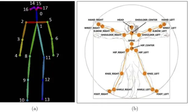
Also, each human pose estimation software uses a specific configuration of the skel-eton model, with different number of body joints (the most common configurations have between 14 and 23 joints). The Figure 7 shows some of these configurations.
(a) (b)
Figure 7:(a) OpenPose output format (COCO) ; (b) Joints tracked by the Kinect sensor
In conclusion, several software packages have been developed for human pose estima-tion from RGB images or depth images, being the ones based on CNNs the most prom-ising ones.
For the incorporation of these software packages in robotic applications in real time it is fundamental to use them from ROS.
In general, the modules for 2d pose estimation from single images are the most
de-veloped and there are even some quite effective open source packages that have reached a certain popularity. In particular, OpenPose (based on Convolutional Neural Networks architecture) is an efficiente open source software for2dreal-time multi-person pose
es-timation [7].
On the other hand, considering the availability of hardware to carry out this work (we have a Logitech C300 webcam and a Kinect One camera that will be described in the next chapter), we considered the implementation of a package ROS that allows2dpose
estimation from simple RGB images [2].
Additionally, a ROS node that can obtain 3dpose estimation from the initial 2dpose
estimation and a depth image synchronized with the RGB image (as in the Kinect cam-era), by means of projecting pose2dpose estimation onto the point-cloud of the depth
image, has been developed [2].
In this way we can have a software package adaptable to the available hardware, that will allow us to obtain2dpose estimation or 3dpose estimation depending on the type
3 General Architecture of the System
This chapter provides information about the general structure of the system, the hard-ware devices and the softhard-ware implemented.
The functional architecture is designed to accomplish the objectives presented in chapter 1.
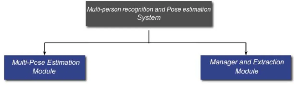
Figure 8 shows the general architecture of the Multi-Person Pose Estimation Module and the connectivity between its modules.
Figure 8: System Architecture
The first module consists of the multi-person human pose estimation process which identifies and recognises the people that appear in the images captured by a single camera. This subsystem estimates the pose for each recognised persons in the coordinate system of the camera that takes the images.
The second module carries out the process of managing the information given by the other module (camera sensor, human pose estimation and coordinate data points) and extracting the data outputs, so that they can be easily read and handled from another ROS program.
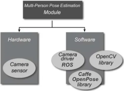
Figure 9:Architecture of Multi-Person Pose Estimation Module
and Figure 10 presents the managing and extraction module.
Figure 10: Architecture of Managing and Extraction Module
The difference between the physical (hardware) and non-physical (software) entities is clear and evident in the most engineering projects like the present one. Thus, two schema, one for hardware and other for software will be constructed.
3.1 Hardware Architecture
The hardware architecture refers to the identification and description of the system phys-ical components and their interactions and compatibility with the system architecture. The hardware used in this project consist of camera sensors and a computer that man-ages the whole system. The graphics card (GPU) that we have used in this is work is a NVIDIA GeForce GTX 1080 (Driver Version: 381.22).
Also, Logitech C300 webcam (Figure 11) and Kinect One camera (Figure 12) have been used in this project. Logitech C300 is a video camara and its 5-megapixel photo capture allows high-resolution2dsnapshots. Its technical specifications are presented in
Table 1.
Figure 11: Logitech C300 webcam
Table 1: Logitech C300 webcam technical specifications
Depth imaging technology has advanced dramatically over the last few years, and has finally reached a consumer price point. The Kinect One (video game sensor developed by Microsoft) uses a depth camera based on Time-of-Fligth (ToF) technology.
In a depth image, pixels indicate the calibrated distance in meters of 3d points in
the world from the imaging plane, rather than a measure of intensity or color. The RGB-D format of the stream input captured by a Kinect sensor combines visual (RGB colours) and geometric information (depth) in a synchronized format that provides us with the possibility of extracting features from both [20]. This camera is widely used in the robotics community in the field of computer vision due to its low cost. Their technical specifications are present in Table 2.
Figure 12: Kinect One components
3.2 Software Architecture
The software architecture identifies and describes the system non-physical components and their interaction and compatibility with the system architecture. Computer software interprets the information provided by the physical hardware. Software can be divided into application software and system software.
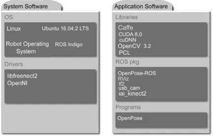
The first one uses the computer system to perform a specific functionality for the benefit of the user (computer program). The second one includes operating systems, which manage the resources and provide common services for other software working on top of them and device drivers which control the devices connected to the computer [18]. The Multi-Person Pose Estimation System is programmed in C++ language and uses the components shown in Figure 13, that describes the system software and the applic-ation software used in this work. Additional informapplic-ation of each one is presented in the following sections.
Figure 13: Main software components used in this work
3.2.1 Robot Operating System (ROS)
The Robot Operating System (ROS) is a framework for building robot software. It started at the Stanford University in the mid-2000s by the Stanford AI Robot (STAIR) and the Personal Robots (PR) program. It is an open source software with a large variety of tools, libraries and conventions that simplify the work of creating complex and robust robot applications with a wide variety of robotic platforms. The ROS community exchanges robot software and knowledge through ROS distributions that make easier to install a collection of software. It provides repositories where different institutions can develop and release their own robot software and a ROS wiki where anyone can contribute with his/her own documentation and tutorials.
Software in ROS is organized in packages. A package might contain ROS nodes, a ROS-independent library, a dataset, configuration files, a third-party piece of software, or anything else that logically constitutes a useful module. The goal of these packages is to provide useful functionality that is easy-to-consume in a way that the software can be easily reused. A typical structure of ROS package is shown in Figure 14. The structure of the package folders is as follows:
Figure 14: Structure of a typical ROS package [12]
• config: All configuration files that are used in this ROS package are kept in this folder. This folder is created by the user and is common practice to name the folder config to keep the configuration files in it.
• include/package_name: This folder consists of headers and libraries that we need to use inside the package.
• scripts: This folder keeps executable Python scripts. In the block diagram, we can see two example scripts.
• src: stores the C++ source codes. We can see two examples of the source code in the block diagram.
• launch: keeps the launch files that are used to launch one or more ROS nodes.
• msg: contains custom message definitions.
• srv: contains the service definitions.
• action: contains the action definition.
• package.xml: This is the package manifest file.
Each package directory has to include a CMakeList.txt and package.xml file that describes its contents and how catkin should interact with it. The commands in catkin are the ROS build system that generates executable programs, libraries and interfaces.
The ROS system uses different nodes that communicate with each other, exchanging information and data. However, the whole system needs a running ROS Master in order to notice nodes the existence of other nodes and starting to communicate with each other. The ROS Master enables individual ROS nodes to locate one another in the system and it tracks publishers and subscribers to topics and services. The communications between nodes can be done with client/server or publisher/subscriber methodologies. ROS topics implement a publish/subscribe communication mechanism and ROS services and actions uses a client/server communication method. Figure 15 shows a representation of these three communication ways between nodes.
Figure 15: ROS comunication mechanisms [18]
One of the most common ways to exchange data in a distributed system is a pub-lish/subscribe communication mechanism implemented by topics. Before node (A) starts to transmit data over topics, it must first advertise the topic name and the type of mes-sage that is going to be sent. Node (B) and node (C) have to subscribe to this topic by making a request to ROS Master. Then, both nodes will receive messages from this topic. A topic is one-way communication and it is useful if there are multiple nodes listening.
A service is a synchronous two-way communication that allows one node to call a func-tion that is executed in other node. The server node specifies a funcfunc-tion and advertises the service. By making a request, the client node can access this service and then, await a response from the server node.
An action is an asynchronous two-way communication between nodes. It is similar to the request and response of a service. An actions is requested with the aim of obtaining a result. Moreover, the server node can provide feedback for some updates on the progress and the client node can cancel the previous request at any time.
3.2.2 C++ libraries
This section presents different high-level C++ libraries providing useful utilities. Basic colour image processing algorithms are managed using OpenCV library. Point Cloud lib-rary (PCL) offers the most important point-cloud processing algorithms. Caffe provides multimedia scientists and practitioners with a clean and modifiable framework for state-of-the-art deep learning algorithms and a collection of reference models.
OpenCV: is an open source library licensed under Berkeley Software Distribution (BSD) that provides real-time computer vision applications. OpenCV was developed to provide a common infrastructure for computer vision applications and to accelerate the use of machine perception in the commercial products. OpenCV is a library designed and optimized for displaying2d images. OpenCV application areas include: facial detection
and recognition, human gesture recognition, object segmentation and recognition, motion tracking, produce3dpoint-clouds from stereo cameras, stitch images together to produce
a high resolution image, etc. In this work we have installed and used the version OpenCV 3.2.
Point Cloud Library (PCL): is an open source library for 2d and 3d image and
point-cloud processing under Berkeley Software Distribution (BSD) license and thus free for commercial and research use. Each element of the array contains the Cartesian (x, y, z) coordinates of that point in space and, if available, the RGB data or other
multi-dimensional channels for that point. The PCL library has many algorithms for point-cloud processing such as filtering outliers from noisy data, stitch 3d point-clouds
together, feature extraction to recognise objects based on the geometric appearance, surface reconstruction, registration, segment relevant parts of a scene, etc.
Caffe: is an open source C++ library under BSD-licensed with Python and MAT-LAB bindings for training and deploying general purpose convolutional neural networks (CNNs) and other deep models efficiently on commodity architectures. Caffe fits industry and internet-scale media needs by CUDA GPU computation, processing over 40 million images a day on a single K40 or Titan GPU (≈2.5 ms per image). By separating model representation from actual implementation, Caffe allows experimentation and seamless switching among platforms for ease of development and deployment from prototyping machines to cloud environments. Caffe is maintained and developed by the Berkeley Vis-ion and Learning Center (BVLC) with the help of an active community of contributors on GitHub.
3.2.3 OpenPose
OpenPose is a library for real-time multi-person keypoint detection and multi-threading written in C++ using OpenCV and Caffe, authored by G. Hidalgo, Z. Cao, T. Si-mon, S.E. Wei, H. Joo and Y. Sheikh (Robotics Institute of Carnegie Mellon Univer-sity). The code has been released for full reproducibility and it is maintained and de-veloped by the authors with the help of an active comunity of contributors on GitHub (https://github.com/CMU-Perceptual-Computing-Lab/openpose).
3.2.4 Packages: usb_cam, iai_kinect2, tf2, RViz and OpenPose_ROS
The main ROS packages used in this work are the following:
usb_cam: This is a collection of tools and libraries for ROS to interface with standard USB cameras (e. g. the Logitech Quickcam). It is developed and maintained by:
• Benjamin Pitzer and Russell Toris:
– (https://github.com/ros-drivers/usb_cam).
iai_kinect2: this is a collection of tools and libraries for ROS to interface to the Kinect One device using libfreenect2.
It contains a calibration tool for calibrating the IR sensor to the RGB sensor and depth measurements. It converts raw depth/RGB/IR streams to depth images and registered point-clouds. It is developed and maintained by:
• Thiemo Wiedemeyer from the University of Bremen:
– (https://github.com/code-iai/iai_kinect2).
tf2: tf2 is the second generation of the transform library, which lets the user keep track of multiple coordinate frames over time. tf2 maintains the relationship between coordinate frames in a tree structure buffered in time, and lets the user transform points, vectors, etc between any two coordinate frames at any desired point in time. It is developed and maintained by:
• Tully Foote, Eitan Marden-Eppstein and Wim Meeussen:
– (https://github.com/ros/geometry2).
RViz: The RViz tool is an official3dvisualization tool of ROS. Almost all kinds of data
from sensors can be viewed through this tool. RViz will be installed along with the ROS desktop full installation. It is developed and maintained by:
• Dave Dershberger, David Gossow, Josh Faust and William Woodall:
– (https://github.com/ros-visualization/rviz).
OpenPose_ROS: OpenPose has been converted into popular software and packages for ROS have been very recently developed by:
• CTS Robotics Group of Eindhoven University of Technology:
– (https://github.com/tue-robotics/openpose_ros).
• Kevin Zhang of Carnegie Mellon University:
– (https://github.com/firephinx/openpose_ros).
• Steven Jens M. Jorgensen of University of Texas at Austin:
4 Multi-Person Pose Estimation
Visual interpretation of people plays a central role in the quest for comprehensive image understanding.
A major cornerstone in achieving these goals is the problem of human pose estimation, defined as2dor3dlocalization of human joints on the arms, legs, and keypoints on torso
and face.
4.1 OpenPose (Convolutional Pose Machine)
Convolutional Neural Networks (CNNs) can be incorporated into the pose machine frame-work for learning image features and image-dependent spatial models for the task of pose estimation. At least in the very near future, CNNs are the most promising in creating general detection, tracking, and recognition modules for human-aware robots.
A sequential architecture composed of convolutional networks directly operate on belief maps from previous stages, producing increasingly refined estimates for part locations, without the need for explicit graphical model-style inference.
Convolutional Pose Machines (CPMs) consist of a sequence of convolutional networks that repeatedly produce2dbelief maps for the location of each part (Figure 16). At each
stage, image features and belief maps produced by the previous stage are used as input. The belief maps provide the subsequent stage an expressive non-parametric encoding of the spatial uncertainty of location for each part, allowing the CPM to learn rich image-dependent spatial models of the relationships between parts. The overall proposed multi-stage architecture is fully differentiable and therefore can be trained in an end-to-end fashion using backpropagation [25].
At a particular stage in the CPM, the spatial context of part beliefs provide strong disambiguating cues to a subsequent stage. As a result, each stage of a CPM produces belief maps with increasingly refined estimates for the locations of each part.
In order to capture long-range interactions between parts, the design of the network in each stage of our sequential prediction framework is motivated by the goal of achieving a large receptive field on both the image and the belief maps [25].
Based on CPM architecture, OpenPose is an efficiente method for multi-person pose estimation (Figure 19) what uses a nonparametric representacion of association scores via Part Affinity Fields (PAFs), a set of 2d vectors fields that encode the location and
Figure 16: Architecture of Convolutional Pose Machines (CPMs) [25]
Figure 17: Overall pipeline of OpenPose software [7]
The part affinity is a2dvector field for each limb for each pixel in the area belonging to
a particular limb, that encodes the direction that points from one part of the limb to the other. Each type of limb has a corresponding affinity field joining its two associated body parts. A greedy parsing algorithm is sufficient to produce high-quality parses of body poses, that maintains efficiency even as the number of people in the image increase [7].
Figure 17 illustrates the overall pipeline of OPenPose software [7].
• OpenPose takes, as input, a color image of size w×h (Fig. 17a) and produces,
as output, the 2d locations of anatomical key-points for each person in the image
(Fig. 17e).
• First, a feed-forward network simultaneously predicts a set of2dconfidence maps
of body part locations (Fig. 17b) and a set of 2d vector fields of part affinities,
which encode the degree of association between parts (Fig. 17c).
• Finally, the confidence maps and the affinity fields are parsed by greedy inference (Fig. 17d) to output the 2dkeypoints for all people in the image.
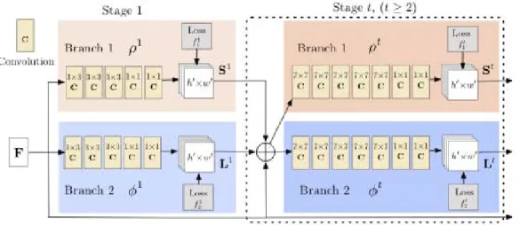
Figure 18: Architecture of the two-branch multi-stage CNN in OpenPose
The architecture of OpenPose, shown in Figure 18, simultaneously predicts detection confidence maps and affinity fields that encode part-to-part association. The network is split into two branches: the top branch, shown in beige, predicts the confidence maps, and the bottom branch, shown in blue, predicts the affinity fields. Each branch is an iterative prediction architecture, Following the typical structure of a CMP, which refines the predictions over successive stages, with intermediate supervision at each stage [7].
The runtime analysis, performed on a laptop with one NVIDIA GeForce GTX-1080 GPU, has shown that this software has achieved the speed of 8.8 fps for a video with 19 people, which would allow its use in real-time applications.
OpenPose takes a2dcolor image as input and produces the2dlocations of anatomical
key-points for each person in the image as output (Figures 19 and 20). The (x, y)
coordinates of the final pose data array can be normalized to the range: [0, sourcesize], [0, outputsize], [0,1], [−1,1], depending on the flag keypoint_scale. The values can be
assigned to this flag are: 0to scale it to the original source resolution; 1to scale it to the
net output size (set with net_resolution);2 to scale it to the final output size (set with
resolution);3 to scale it in the range[0,1]; and4 to scale it in the range[−1,1].
The OpenPose library main functionalities are:
• Multi-person 15 or 18-keypoint body pose estimation and rendering.
• Running time invariant to number of people on the image.
• Image, video and webcam reader.
• Able to save and load the results in various formats (JSON, XML, PNG, JPG, ...). The code has been publically released by the Robotics Institute of Carnegie Mellon University for full reproducibility, representing the first real-time open source system for multi-person2dpose detection.
Figure 19: Multi-person pose estimation with OpenPose [7]
4.2 ROS Wrapper for OpenPose
OpenPose has been converted into popular software and, taking into account the Open-Pose functionalities for 2dpose estimation and its open-source condition, several groups
have considered incorporating all their functionalities into a simple-to-use ROS wrapper. The ROS wrapper for OpenPose is a open C++ software application working on ROS that obtains a 2dmulti-person pose estimation from a simple camera.
From the previous work, and particularly the OpenPose_ROS package published by Steve Jens M. Jorgensen (NSTRF Fellow at NASA and PhD Student at The University of Texas at Austin, to which we especially thank for the help provided), we have imple-mented a ROS wrapper that automatically recovers the pose of several people from a single camera RGB using OpenPose (Figure 21) [2].
Figure 21: OpenPose-ROS package
A simplified scheme of the operation of the OpenPose_ROS package is shown in the Figure 22, where the topics are mentioned in a rectangle and nodes are represented in ellipses.
On the one hand, we introduce the flow of images, which in our case we do using the usb_cam driver.
This image stream (Figure 23) is visualized by image_view, which is independent of the openpose ROS wrapper.
Figure 23: Image from /usb_cam
The topics in the OpenPose_ROS package (openpose_ros_pkg) are as follows:
• /openpose_ros/input_image:
– Publisher: openpose_ros_node.
– The image that is received from the camera, and is next used to do the seg-mentation with OpenPose, is published by the node openpose_ros_node at the topic /openpose_ros/input_image for further comparisson with the im-age with the skeleton drawn in it. The messim-ages published in this topic are of type sensor_msgs::Image. The is no subscriber for this topic as this is only for user’s visualization.
• /openpose_ros/detected_poses_image:
– Publisher: openpose_ros_service_node.
– The image processed by OpenPose with the skeleton drawn in it, is pub-lished in this topic by the openpose_ros_service_node implemented inside the node openpose_ros_node. The messages published here are of type sensor_msgs::Image (Figure 24).
Figure 24: Image processed by OpenPose with the skeleton drawn in it
• /openpose_ros/detected_poses_kepoints:
– Publisher: openpose_ros_service_node.
– The estimated 2dpositions of the keypoints and the confidence of the
estim-ation are published in the topic /openpose_ros/detected_poses_keypoints. They are published by the openpose_ros_service_node as a response of the image sent as a request. This topic has no subscribers contained in this pack-age as these data are published for further analysis in other packpack-ages.
Figure 25 shows an example of the output. The message has not an standard format so we have defined it.
The message contains a field for the number of people detected, a field for the ID of each detection and a field for each bodypart. Each bodypart contains a field for the x coordinate, for the y coordinate and for the confidence of
the estimation (Figure 26). It should be noted that normally we use model COCO and we get 18 bodyparts, since it is the one that uses the program, and it does not seem that the computing capacity is a limit.
In addition, we see how each measure is associated with your time stamp, as in every ROS message.
Figure 25: Outoput of openpose_ros/detected_poses_keypoints
Figure 26: Message published by openpose_ros_service_node
The topics that are involved while running the 2ddetection and the flow between them
can be seen in the scheme shows in Figure 27. These are all topic while running open-pose_ros_node at the same time as openopen-pose_ros_node_firephinx during the publica-tion of images from a camera.
The services in the OpenPose_ROS package (openpose_ros_pkg) are as follows:
• detect_poses:
– Server: openpose_ros_service_node→Client: openpose_ros_node_firephinx.
– Request: Input image→ Response: Detections.
– The service involved is the service detect_poses implemented inside open-pose_ros_node. The service request field is .image of type sensor_msgs::Image and the service response field is .detections and is associated to a vector where the detections of one image are stored (Figure 28).
A workflow diagram of the OpenPose_ROS package shows in Figure 29.
Figure 29: Workflow diagram of the OpenPose_ROS package
4.3 Skeleton-3d Package
Through this node, we can project the2dpose detections provided by the OpenPose_ROS
wrapper in the point-cloud of the depth images, to obtain an 3d multi-person pose
es-timation in real-time at the camera space coordinate system [2].
For the Kinect camera, the camera space (that is to say, the3dcoordinate system used
by the camera) is defined as follows (Figure 30):
• the origin (x= 0, y= 0, z= 0) is located at the center of the IR sensor. • xgrows towards the left of the sensor,
• y grows upwards (note that this direction is based on the sensor’s tilt), • zgrows out in the direction the sensor is facing, and
Figure 30: The Kinect camera space coordinate system
Depth space is the term used to describe a 2d location on the depth image. It can be
considered as a row/column location (index value, i) of a pixel, where x is the column
and y is the row.
So, for a 960×540resolution depth image, the pointx= 0,y= 0 (i= 1) corresponds
to the top left corner of the image, and the point x= 960,y = 540 (i= 518400) is the
bottom right corner of the image.
In some cases, az value is needed to map out of depth space. For these cases, simply
locate the value associated with the point of the depth image located in the row/column in question, and use that value (which is the depth in millimeters) directly asz.
To know the value of the depth coordinate associated with a pixel of the color image, the operation is relatively easy because the depth and the infrared come from the same sensor in Kinect camera. It is simply necessary to locate the row/column (index value) corresponding to that pixel in the depth image.
The principle of operation is based on associating the pixel corresponding to the co-ordinates (usually in pixels) provided with the openpose in the 2d image of the RGB
camera with the corresponding points (or pixels) of the point-cloud of the 3d image of
the depth camera.
The correspondence between the pixels of RGB image and the points of the point-cloud image, according to the coordinate system used by OpenPose and PointCloud, is shown in Figure 31.
Since a body joint "occupies" on the2dimage a "size" larger than a single pixel, and to
prevent an incorrect reading of the depth camera at a particular point is very important, projection onto the point-cloud of body joints were performed considering the pixels of a 3x3 square, centered at the point corresponding to the coordinates extracted by
OpenPose. The arithmetic mean of the depth readings detected at those 9 points was performed.
In this way we extract the 3d "real world" coordinates (in the camera space system)
Figure 31: Correspondence between pixels in RGB and point-cloud images
The skeleton-3d package has two main nodes (Figure 32).
Figure 32: Skeleton-3d package
The services in this package are as follows:
• detect_poses:
– Server: openpose_ros_service_node_3d→Client: skeleton_extract_3d_node.
– Request: Input image→ Response: Detections.
– The service involved is the service detect_poses is implemented inside open-pose_ros_node.
The relevant topics in the skeleton_extract_3d_node node are the following:
• /openpose_ros/skeleton_3d/detected_poses_image:
– Publisher: openpose_ros_node_3d_node.
– In this topic we are publishing, as we did in2dpose detection, the images with
the skeleton drawn. We have selected another name so it will not conflict if we want to run the2ddisplay simultaneously. There is no subscriber.
• openpose_ros/skeleton_3d/detected_poses_keypoints:
– Publisher: openpose_ros_node_3d_node.
– In this topic we are publishing the 2dpose detections with the same format.
There is no subscriber.
• /openpose_ros/skeleton_3d/detected_poses_keypoints_3d:
– Publisher: skeleton_extract_3d_node.
– This topic displays the3ddetections in real world coordinates. The format is
shown in Figure 33. This message has the same fields as2ddetections with the
particularity that the x, y, z coordinates are real numbers and are in "world
coordinates" (referred to camera space). There is no subscriber.
Figure 33: Format of the3ddetection message
• /openpose_ros/skeleton_3d/input_pointcloud:
– Publisher: skeleton_extract_3d_node.
– In this topic the depth images received are published when a synchronized RGB image has been found.
• /openpose_ros/skeleton_3d/input_rgb
– Publisher: skeleton_extract_3d_node.
– The RGB images received are published in this topic .
The relevant topics in the skeleton_extract_3d_visualization_node node are the follow-ing:
• /openpose_ros/skeleton_3d/visualization_markers: In this topic, the markers cor-responding to each joint are published in the form of sphere_list (Figure 34). You can adjust various parameters, such as the color, size and shape of markers. These markers can be easily visualized in RViz, which gives us the tool for3dvisualization
of the human pose estimation.
Figure 34: Markes for visualization of bodyjoints in RViz
• /openpose_ros/skeleton_3d/visualization_skeleton: In this topic we publish the "skeleton" detected. To do this, we simply attach the previously published markers using lines to obtain a human skeleton. We publish this skeleton in the form of a line_list. As in the previous case, we can visualize it with RViz (Figure 35a). If we visualize both, the skeleton and the body members, at the same time, the view would be as shown in the Figure 35b.
Summarizing, the operation of the skeleton_extract_3d_visualization_node node can be described as follows (Figure 36): we process the message published by the skel-eton_extract_3d_node node, and publish a message visualization_msgs::marker type, in which the position of the points are obtained by assigning the estimated 3dposition
(a) (b)
Figure 35: Skeleton in RViz with: (a) line_list and (b) sphere_list+line_list
5 Results
This chapter describes the results obtained in this work, the functionalities and the operation of the ROS packages implemented.
5.1 Human pose detection and visualization
In principle, the mode of operation is streaming and the images captured by the video camera are processed to obtain the multi-person pose estimation in real-time.
The main functionality of this software is 2d multi-person pose estimation from the
RGB images emitted by a single camera.
The results obtained (2d real-time multi-person pose estimation) with the streaming
processing of RGB images captured by a single webcam are shown in the Figure 37.
Figure 37: 2dreal-time multi-person pose estimation from RGB images captured by a webcam
The processing of the RGB images allows us to obtain a confidence value for the estimation of the position of each body joint, as shown in the Figure 38.
We have also verified that the coordinates of the obtained keypoints correspond ef-fectively with those of the segmented image, as seen in the Figure 39. Note that the coordinates (in pixels) are rotated 180º and located in a specular way to the image that we visualize.
Figure 38: Confidence for some2dkeypoints estimation
Figure 39: 2dkeypoints coordinates and correspondence with segmented image
When the camera captures simultaneously RGB and depth images (RGB-D image), the software projects the body joints of 2d pose estimation, extracted from the RGB
image, onto the point-cloud obtained by the depth camera and extracts3dmulti-person
pose estimation (Figure 1). This3dpose estimation can be visualized in RViz.
The results obtained (3d real-time multi-person pose estimation) with the streaming
processing of RGB-D images captured by a Kinect One are shown in Figure 40. As we can see, the code matches the2ddetections in the RGB with the pointcloud succesfully
Other mode of operation is the reproduction of images previously stored in a bag. A bag is a file format in ROS for storing ROS message data. Bags (so called because of their .bag extension) have an important role in ROS, and a variety of tools have been written to allow to store, process, analyze, and visualize them. Bags are the primary mechanism in ROS for data logging, which means that they have a variety of offline uses. Researchers can use the bag file toolchain to record datasets, then visualize, label, and store them for future use.
Using bag files within a ROS Computation Graph is generally no different from having ROS nodes sending the same data, though it can run into issues with timestamped data stored inside of message data. For this reason, the rosbag tool includes an option to publish a simulated clock that corresponds to the time the data was recorded in the file. The bag file format is very efficient for both recording and playing back, as messages are stored in the same representation used in the network transport layer of ROS.
The process of extracting archived images from a bag is shown in Figure 41.
Figure 41: Extraction and processing of images from a bag
We consider that it is interesting to be able to use sequences corresponding to image databases, to contrast and validate the operation of the software that we have implemen-ted. The images obtained from the database will be overturned to a bag, so that they can be processed in this ROS packages.
The bag is prepared for the data to be published in the same topics that have been configured to publish the images coming from the camera.
Using the ROS nodes (openpose_ros_node and openpose_ros_node_firephinx), the images extracted from the bag are processed as if a camera were connected. The Figure 42 illustrates the processing of images obtained from a bag.
Figure 42: Processing of images obtained from a database
For example, in 2016 the Institut de Robòtica i Informàtica Industrial (IRI) prepared a database with RGB-D human images obtained with Kinect One and simultaneously recorded the position of a series of markers with OptiTrack System [3]. This database allows to know the position of certain bodyjoints of the person whose movements have been registered with OptiTrack and also captured with RGB-D images (Figure 43).
Therefore, we can compare the estimates of the position coordinates of the keypoints, obtained with this ROS packages for 3d pose detection, with their true coordinates,
recorded by Optitrack System, to contrast and validate the results obtained.
5.2 Proccessing speed
If we record a rosbag and, by running rqt_bag, we have a look at the frequency that the
3ddetections are sent, we obtain the results shown in the Figure 44.
Figure 44: Frequency of the 3ddetections
We can see that we get around seven detections per second. This is a satisfactory result that allow the management of the3dpose estimation practically in real time. Processing
time is less than the minimun required for a robot to do a task involving human-robot interaction.
If we record a rosbag with all the topics published by the package, we can see the results shown in the Figure 45.
Figure 45: Messages published within the Skeleton-3d package
The first message to arrive, naturally, are the point-cloud and the RGB images. Next, the OpenPose2ddetection, that is the task that clearly takes more time. The following
3d detection and the visualizer messages are published after a very short time interval.
This results shows that the implemented code is quite efficient, so it is not necessary to introduce more optimizations, because the proccesing time is little compared to the proccesing time of OpenPose package.
5.3 Limitations
The software works quite well but has, of course, some limitations. The most significant limitation is the occlusions of some part of the body, particulary when trying to obtain
3d human pose estimation. OpenPose solves fairly well the 2d human pose estimation
Figure 46: OpenPose with occlusions
But this is not the case with the software we have implemented for 3d human pose
estimation. We extract the depth coordinate from the point-cloud, given a 2d pixel
coordinate in the RGB image. But what happens if the camera is at one side, fo instance, the left side of a person, as in Figure 47.
Figure 47: OPenPose with occlusions: camera in the left side
As the camera is in the left side, the detection of the left shoulder will be quite accurate, but what about the right shoulder? As we see, it is behind the chest in the image but OpenPose still detects it. But when we take the depth coordinate of the right shoulder we will use instead the depth coordinate of the chest. That means that our software for
Figure 48: Camera in the left side: 2dand 3dpose estimations
The results when one joint is hidden are described in the Figures 48 and 49. Figure 48 shows the same view in the RGB image and in the depth image. To calculate the depth coordinate, we can move in the cloud of points to check the same with a view from above, as shown in the Figure 49. We can see that the x,y coordinate are taken correctly, but
when taking the depth coordinate,z, we have taken the depth of the bodypart that is in
front. In our case, we are taking the depth coordinate of the left shoulder instead of the right shoulder.
Figure 49: Camera in the left side: 3dpose estimation - View from above
With the method we have used to estimate the 3d pose, it is impossible to estimate
the position of the occluded parts as we do not have their depth coordinate. We could try some filtering to obtain the detections of the occluded part.
6 User Guide
This chapter describes the ROS implemented packages to facilitate its use.
• ROS wrapper for OpenPose (https://github.com/CMU-Perceptual-Computing-Lab/openpose - see commit number a1e0a5f4136e702b5731a268c2993fb75ca4753c) allows the estimation of
2dmulti-person pose from a single RGB camera.
• When a depth image is synchronized with the RGB image (RGB-D image), a 3d
extractor node has been implemented to obtain3dpose estimation from the2dpose
estimation given by OpenPose through the projection of the2dpose estimation onto
the point-cloud of the depth image. Also, a visualization node for the 3d results
has been implemented.
The package is accessible on the repository GitHub [2]:
https://github.com/MiguelARD/openpose_ros-1.
6.1 Installing OpenPose ROS Wrapper
1. Install openpose and its dependencies ( https://github.com/CMU-Perceptual-Computing-Lab/openpose/blob/master/doc/installation.md)
2. Enable the package running in openpose_ros directory: ./install_openpose_and_enable_package.sh 3. Install PCL (http://pointclouds.org/downloads/) 4. If it succeds, compile: cd ~/catkin_ws/src catkin build cd .. source devel/setup.bash
6.2 Running the OpenPose ROS Wrapper and the
3d
Pose
Extractor
The package can be divided into two modules that work independently. One for2dpose
detections, with a visualization tool like the one in OpenPose but implemented in ROS. And another for 3dpose detections, with a visualization node to view the results with
RViz. We use the same node to get OpenPose 2ddetections for both modules, but we
have duplicated it and the services it provides with different names to avoid trouble while calling it with the 2dvisualization tool and the3dextractor node simultaneously.
6.2.1 2d Detection Module
This module is composed of a service node for getting2ddetections and a node for the
output visualization.
First of all, you might want to change some things in the code to adapt it to your necessities:
• Go to /openpose_ros_pkg/src/openpose_ros_node_firephinx.cpp, and change "/usb_cam/image_raw" for the topic your camera is publishing the sensor_msgs::Image messages to:
• You may change the output image resolution. To do so, go to /openpose_ros_pkg/src/openpose_ros_node_firephinx.cpp and change:
Now you can run the code. First connect a RGB camera and run the corresponding ROS drivers to start to publish the images (they must be image_raw). For example you can connect a webcam and use https://github.com/ros-drivers/usb_cam. With this drivers run:
roslaunch usb_cam usb_cam-test.launch You should get the something like:
Then, initialize the2ddetection service node:
rosrun openpose_ros_pkg openpose_ros_node
If everything works fine you should see the following output in your shell: [ INFO] [1501140533.950685432]: Initialization Successful!
Finally, to get the 2dposes of the images from the camera and visualize the output,
run:
rosrun openpose_ros_pkg openpose_ros_node_firephinx You should obtain something similar to:
If everything is running correctly, the package should be publishing in the topics: /openpose_ros/input_image
/openpose_ros/detected_poses_image /openpose_ros/detected_poses_keypoints
• /openpose_ros/input_image: The images the 2d detection node is taking to
make the segmentation are published here.
• /openpose_ros/detected_poses_image: Images with the segmentation skeleton drawn in it are published here.
• /openpose_ros/detected_poses_keypoints: In this topic, the messages with the
2ddetections keypoints (openpose bodyjoints) are being published. The messages
- num_people_detected: number of people that are in the image.
- person_ID: ID number assigned to each person.
- bodypart (i.e. Nose): Each bodypart has the following fields:
– x: x openpose keypoint pixel coordinate.
– y: y openpose keypoint pixel coordinate.
– confidence: confidence of the detection. If you write the data in a csv it should be like this:
6.2.2 3d Detection Module
This module is composed of the same2dextractor node described in the previous section,
a node for getting3dpose detection and a node for visualization of the output in RViz.
We can see the resulting3dhuman skeleton and the resulting3ddetections for the joints
or both at the same time with the visualization node. An RGB-D camera is needed to run this module.
First of all you might want to change some things in the code to adapt it to your necessities:
• Go to /skeleton_extract_3d/launch/openpose_skeleton_extract.launch. You will see this:
– Here you should change “/usb_cam_3d/image_raw/” for the topic your cam-era will be publishing the sensor_msgs::Image messages (RGB images). You should also change “/kinect2/qhd/points” for the topic your camera will be publishing the sensor_msgs::Pointcloud2 messages (depth images).
• Go to /skeleton_extract_3d/src/skeleton_extract_3d_node.cpp and set the in-put resolution of the images (the resolution of the depth and the RGB images must be the same):
• Go to /skeleton_extract_3d/src/skeleton_extract_3d_visualization_node.cpp. You might want to change the color, shape, size etc. of the markers. To see the options you have go to http://wiki.ros.org/rviz/DisplayTypes/Marker.
– To set the options of the bodyjoints:
– To set the options of the skeleton, go to:
Once you have set the options repeat step 4 of the installation process. Now that you have configured it, you can run the code. First of all, connect your RGB-D and run the corresponding ROS drivers.
For example you can use a KinectOne and https://github.com/code- iai/iai_kinect2 ROS drivers. To initialize the camera with this drivers run:
roslaunch kinect2_bridge kinect2_bridge.launch rosrun kinect2_viewer kinect2_viewer Then you will see the camera output:
Once your camera is publishing, launch the 2d extractor node and the 3d extractor
node by running:
roslaunch roslaunch skeleton_extract_3d openpose_skeleton_extract.launch If everything is working fine you should have something similar to:
Then you can run the visualization node:
rosrun skeleton_extract_3d skeleton_extract_3d_visualization_node
Note: To have the fixed frame for visualization you must run:
rosrun kinect2_bridge kinect2_bridge _publish_tf:=true.
Now open RViz and select as fixed frame the one you have set for the markers. For example, I have chosen:
kinect2_ir_optical_frame. Select the topics:
/openpose_ros/skeleton_3d/visualization_markers, and /openpose_ros/skeleton_3d/visualization_skeleton, and you should have something similar to:
If everything is running correctly the package should be publishing in the following topics: /openpose_ros/skeleton_3d/detected_poses_image /openpose_ros/skeleton_3d/detected_poses_keypoints /openpose_ros/skeleton_3d/detected_poses_keypoints_3d /openpose_ros/skeleton_3d/input_pointcloud /openpose_ros/skeleton_3d/input_rgb /openpose_ros/skeleton_3d/visualization_markers /openpose_ros/skeleton_3d/visualization_skeleton
• /openpose_ros/skeleton_3d/detected_poses_image: the same kind of mes-sages are published in this topic as in topic:
/openpose_ros/detected_poses_image in the 2dmodule.
• /openpose_ros/skeleton_3d/detected_poses_keypoints: the same kind of mes-sages are published in this topic as in topic:
/openpose_ros/detected_poses_keypoints in the2dmodule.
• /openpose_ros/skeleton_3d/detected_poses_keypoints_3d: the3ddetections
are published in this topic. The fields are the same as the mesagges published in: /openpose_ros/skeleton_3d/detected_poses_keypoints,
but the fields of each bodypart change. Now they are: - x: x real world coordinate of the joint.
- y: y real world coordinate of the joint.
- z: depth real world coordinate of the joint. - confidence: confidence of the2ddetections.
• /openpose_ros/skeleton_3d/input_pointcloud: Here is published the point-cloud that is synchronized with the RGB image from where we extract the x, y,z real world coordinates of the keypoints.
• /openpose_ros/skeleton_3d/input_rgb: the RGB image that we use to make the 2d detections is published in this topic and it is synchronized with the input
• /openpose_ros/skeleton_3d/visualization_markers: the markers to visualize in RViz the3ddetections of the joints are published in this topic.
• /openpose_ros/skeleton_3d/visualization_skeleton: the skeleton to visualize in RViz the3ddetections is published in this topic.
7 Conclusions
At least in the very near future, Convolutional Neural Networks (CNNs) are the most promising tools to obtain general detection, tracking, and recognition modules for human-aware robots. In general, the modules for2dpose estimation from simple images are the
most developed and there are even some quite effective open source packages that have reached a certain popularity. In particular, OpenPose (based on CNNs) is an efficiente open source software for 2dreal-time multi-person pose estimation.
We introduce a ROS wrapper that automatically recovers2dmulti-person pose from a
single camera using OpenPose. Additionally we have developed a ROS node that obtains
3dhuman pose estimation from the initial2dhuman pose estimation, when a depth image
synchronized with the RGB image is captured, projecting the2dpose estimation onto the
point-cloud of the depth image. In this work, we have implemented a software application working on the Robotic Operating System (ROS) that obtains a pose estimation (2d or
3d, depending on the cases) from a simple image (a 2d image obtained with an RGB
camera or a 3dimage -RGB-D- obtained with a depth camera). The mode of operation
is streaming and the images captured by the video camera are processed to obtain the multi-person pose estimation in real-time. The main functionality of the OpenPose_ROS package is 2dmulti-person pose estimation from the RGB images captured by a single
camera. When that camera simultaneously captures RGB and depth images (RGB-D images), the Skeleton-3d package projects the keypoints of2dpose estimation (extracted
from the RGB image) onto the point-cloud obtained by the depth camera and extracts
3dmulti-person pose estimation.
Also, we consider that it is interesting to be able to use sequences corresponding to image databases, to contrast and validate the operation of the software that we have implemented. The images obtained from the database will be overturned to a bag. Us-ing the ROS packages, the images extracted from the bag are processed simulatUs-ing a connected camera. For example, in 2016 the Institut de Robòtica i Informàtica Indus-trial (IRI) generated a database with RGB-D human images obtained with Kinect One andsimultaneously recorded the position of a series of markers with OptiTrack System. This database can be used to contrast and validate the results of the3dpose estimation
obtained with this ROS package.
The analysis of the processing time shows satisfactory results, since this time is less than the minimun required for a robot to do a task involving human-robot interaction. The most relevant limitation in the use of the implemented software is due to fact that the package for3ddetections cannot deal with occlusions.
Finally, we have made a user guide of the ROS packages implemented, to facilitate their utilization to potential users.
Bibliography
[1] M. Andriluka, L. Pishchulin, P. Gehler, and B. Schiele. 2d human pose estimation: New benchmark and state of the art analysis. InThe IEEE Conference on Computer Vision and Pattern Recognition (CVPR), pages 3686–3693, 2014.
[2] Miguel Arduengo. ROS Wrapper for Real-Time Multi-Person Pose Estimation with a Single Camera. https://github.com/MiguelARD/openpose_ros-1, 2017.
[3] Miguel Arduengo, Guillem Alenya, and Frances Moreno-Noguer. Database for 3d human pose estimation from single depth images. Technical report, IRI-TR-16-05, Institut de Robotica i Informatica Industrial, 2016.
[4] F. Bogo, A. Kanazawa, C. Lassner, P. Geher, J. Romero, and M. J. Black. Keep it smpl: Automatic estimation of 3d human pose and shape from a single image. In
EECV, 2016.
[5] E. Brau and H. Jiang. 3d human pose estimation via deep learning from 2d annota-tions. In Fourth International Conference on 3D Vision, 2016.
[6] Martin Bunger. Evaluation of skeleton trackers and gesture recognition for human-robot interaction. Technical report, Master Thesis, Aalborg University, 2013. [7] Z. Cao, T. Simon, S.-E. Wei, and Y. Sheikh. Realtime multi-person 2d pose
estim-ation using part affinity fields. In The IEEE Conference on Computer Vision and Pattern Recognition (CVPR), 2017.
[8] A. Haque, B. Peng, Z. Luo, A. Alahi, S. Yeung, and L. Fei-Fei. Towards viewpoint invariant 3d human pose estimation. In European Conference on Computer Vision (ECCV), October 2016.
[9] J. Huang and D. Altamar. Pose estimation on depth images with convolutional neural network. Report, Stanford University, 2016.
[10] Y.-Q. Jia, E. Shelhamer, J. Donahue, S. Karayev, J. Long, R. Girshick, S. Guadar-rama, and T. Darrell. Caffe: Convolutional architecture for fast feature embedding. In Proceedings of the 22nd ACM International Conference on Multimedia, pages 675–678, 2017.
[11] Steven Jens M. Jorgensen. Human detection, gesture recognition and policy gener-ation for human-aware robots. Technical report, Master Thesis, The University of Texas at Austin, 2016.
[12] Lentin Joseph. Mastering ROS for Robotics Programming. Packt Publishing Ltd. Birmingham, UK, 2015.
[13] J. Martinez, R. Hossain, J. Romero, and J.J. Little. A simple yet effective baseline for 3d human pose estimation. arXiv preprint arXiv:1705.03098, 2017.
[14] D. Mehta, S. Sridhar, O. Sotnychenko, H. Rhodin, M. Shafiei, H.-P. Seidel, W. Xu, D. Casas, and C. Theobalt. Vnect: Real-time 3d human pose estimation with a single rgb camera. In ACM TOG (SIGGRAPH), 2017.
[15] C. Menier, E. Boyer, and B. Raffin. 3d skeleton-based pose body recovery. In
Proceedings of 3rd International Symposium 3D Data Processing, Visualization and Transmission, pages 389–396, 2006.
[16] A. Newell, K. Yang, and J. Deng. Stacked hourglass networks for human pose estimation. In European Conference on Computer Vision (ECCV), 2016.
[17] X. Perez-Sala, S. Escalera, C. Angulo, and J. Gonzalez. A survey on model based approaches for 2d and 3d visual human pose recovery. Sensors, 14, 2014.
[18] Aleix Ripoll Ruiz. Object recognition and grasping using bimanual robot. Technical report, Master Thesis, Escola Tecnica Superior d’Enginyeria Industrial Barcelona, Universitat Politecnica de Catalunya, 2016.
[19] A. De Santis, B. Siciliano, A. De Luca, and A. Bicchi. An atlas of physical human-robot interaction. Mechanism and Machine Theory, 43:253–270, 2008.
[20] J. Shotton, T. Sharp, A. Kipman, A. Fitzgibbon, M. Finocchio, A. Blake, M. Cook, and R. Mooore. Real-time human pose recognition in parts from single depth images.
Mechanism and Machine Theory, 56:116–124, 2013.
[21] L. Sigal. Human pose estimation.Encyclopedia of Computer Vision, Springer, 2011. [22] E. Simo-Serra, A. Quattoni, C. Torras, and F. Moreno-Noguer. A joint model for 2d and 3d pose estimation from a single image. In The IEEE Conference on Computer Vision and Pattern Recognition (CVPR), 2013.
[23] T. Simon, H. Joo, I. Matthews, and Y. Sheikh. Hand keypoint detection in single images using multiview bootstrapping. InThe IEEE Conference on Computer Vision and Pattern Recognition (CVPR), 2017.
[24] D. Tome, C. Russell, and L. Agapito. Lifting from the deep: Convolutional 3d pose estimation from a single image. In The IEEE Conference on Computer Vision and Pattern Recognition (CVPR), July 2017.
[25] S.-E. Wei, V. Ramakrishna, T. Kanade, and Y. Sheikh. Convolutional pose ma-chines. In The IEEE Conference on Computer Vision and Pattern Recognition (CVPR), 2014.
![Figure 3: Optical markers that are tracked in real time to pose estimation [6]](https://thumb-us.123doks.com/thumbv2/123dok_us/9217032.2805843/7.892.193.722.140.517/figure-optical-markers-tracked-real-time-pose-estimation.webp)
![Figure 14: Structure of a typical ROS package [12]](https://thumb-us.123doks.com/thumbv2/123dok_us/9217032.2805843/17.892.217.695.272.479/figure-structure-typical-ros-package.webp)
![Figure 15: ROS comunication mechanisms [18]](https://thumb-us.123doks.com/thumbv2/123dok_us/9217032.2805843/18.892.164.747.407.643/figure-ros-comunication-mechanisms.webp)
![Figure 16: Architecture of Convolutional Pose Machines (CPMs) [25]](https://thumb-us.123doks.com/thumbv2/123dok_us/9217032.2805843/22.892.145.769.129.409/figure-architecture-convolutional-pose-machines-cpms.webp)
![Figure 19: Multi-person pose estimation with OpenPose [7]](https://thumb-us.123doks.com/thumbv2/123dok_us/9217032.2805843/24.892.186.757.140.481/figure-multi-person-pose-estimation-with-openpose.webp)
