Maintenance Today and Future Trends
Andrew Starr, Basim Al-Najjar, Kenneth Holmberg, Erkki Jantunen, Jim Bellew and Alhussein Albarbar
Abstract. This chapter describes the state of the art in maintenance and its future trends. The key areas that have influenced maintenance in the last 40 years are
management of people and assets, and technological capability. These areas are important because they aim to take the best advantage of expensive resources, whether that advantage be profit, or to provide the best possible service with lim-ited resources. The chapter first sets out the current range of maintenance in indus-trial practice. It is recognised that many businesses do not undertake the full extent of the work reported here, but it is our purpose to survey the state of the art. The chapter then continues to survey the influences of nascent technologies and ideas, before making some predictions about the future. Indeed, some of the most ad-vanced condition-based maintenance effectively aims to predict the future. How-ever, here we do not offer a crystal ball calibrated to international standards; we will constrain ourselves to an informed, independent opinion.
2.1 State of the Art in Management
Maintenance today contributes to the aim of sustainable development in society, including environmental and energy saving aspects, safety aspects and economical aspects. Advanced maintenance has a critical role to play in improving companies’ competitiveness. Technology will not be effective without excellent management. The reliability and availability of machines and instruments are crucial factors of competitiveness, particularly in applications where safety and availability are im-portant. Automation and integrated production have resulted in larger technical
systems, which are more difficult to control, and more sensitive and vulnerable to diverse consequential effects because of breakdowns.
Reliability, availability and lifetime planning first advanced in the nuclear en-ergy industry. The aerospace industry quickly followed, developing methods to assure reliability by distributing and duplicating the crucial features. Safety and risk analyses have been developed and adapted not only in the chemical industry but to some extent in most industrial fields.
However, existing methods are not always so easily applicable to conventional power plants, or to the process and metal industries, where availability is often a more important criterion than reliability. In other words, the downtime is more important than a small probability of failure. A failure can be acceptable if the re-pair and restarting times are short. Maintainability and maintenance support per-formance are therefore most important in such cases.
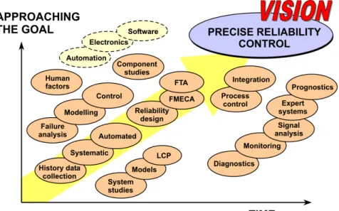
Figure 2.1 The fusion and advance of maintenance technologies
Traditionally, the manufacturer guaranteed the faultless action of a product for a certain warranty period. Nowadays, life cycle profit (LCP) planning is gaining popularity and it is based on the reliability of a product during its whole lifetime. Statistically-defined failure frequency, availability, and the lifetime of the product can now be used as a competitiveness argument. This will also give a reliable ba-sis for recycling a product.
Higher reliability of industrial plants and machines means fewer risks, both personal and environmental, and better control, as well as energy conservation and lower expenses during the operating lifetime. The international competitiveness of the industry can be improved by developing new techniques and methods to
spec-ify and control the product reliability more precisely and convincingly. This is a very important sales argument in a situation where the gap between different products, in terms of performance and functional features, diminishes as a result of extremely advanced product development driven by competition.
Today’s product design methods are mainly based on optimising the perform-ance of the products and little attention is given to reliability and lifetime estima-tions. Few design tools emphasise reliability and availability.
This fusion of technologies is illustrated by Figure 2.1, in which the influence of a wide range of technological advances is considered over the last two decades. Because of the great variety of different techniques, based on expert knowledge in several fields of technology involved, there is a need to approach the reliability and maintainability problems from a general, holistic point of view, starting from the problem of the customer and ending with the satisfied user. The Technical Re-search Centre of Finland (VTT) has developed a systematic approach (Holmberg 2001, Holmberg and Helle. 2008). This is aimed at improving the synergistic in-teractions between the different fields of expertise by showing a logical and com-prehensive structure, where each expert can find his place and see the connections to experts from other fields, all working with the same aim of a satisfied end user, as shown in Figure 2.2.
ANALYSIS IMPROVEMENT
Probability of personal-, equipment-and environmental damage Accident consequence estimation
CORRECTIVE ACTION - change of component - improved design - monitoring - automatic diagnostics - inspections - service - redundancy - operational tests
WEAR CORROSION CREEP FATIGUE FRACTURE
ANALYSIS OPTIMIZATION RISK ESTIMATION FAILURE PROBABILITY LIFETIME ESTIMATION RISK CONTROL RELIABILITY CONTROL
Identification of critical parts System failure- and lifetime probability Estimation of operability costs (LCC)
HUMAN ERROR CONTROL SOFTWARE FAILURE CONTROL ELECTRONICS FAILURE CONTROL MECHANICAL COMPONENT FAILURE CONTROL
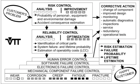
Figure 2.2 Holistic approach to maintenance integration
The probability of personnel, equipment and environmental damage can be analysed and the accident consequences estimated by systematic methods of risk control. The critical parts are identified, the probability of system failure and life-time are calculated, and the operability costs are estimated by statistically based techniques of reliability control. When the critical parts of the production system
that need improvement have been identified, the right techniques and tools for im-provement actions are found in the fields of mechanical component failure control, electronics failure control, software failure control or human error control.
When a critical function is identified, such as the wear endurance life of a cer-tain component, a component operability analysis is carried out; this includes an analysis of the old solution, a robust lifetime design approach to recommended improvements, an analysis of the new solution and, as a result, the improvement actions with estimated improved failure probability and probable lifetime.
The recommended measures to be taken can be a change of component, redun-dancy, improved design, extended monitoring, automatic diagnosis, inspections, operational tests or service instructions. The output of the holistic approach is rec-ommendations for improvements together with estimations of their effects on the risks, the probability of failure and the lifetime.
2.2 Integrated Programmes and Planning Processes
The holistic maintenance concept has been developed extensively during the last decades. As noted above, a significant driver was the reliability of nuclear power and aircraft, but the competiveness of the manufacturing industry, coupled with improvement in transport areas, has led to a range of integrated programme phi-losophies and holistic planning processes. These include reliability centred main-tenance, total productive mainmain-tenance, total quality mainmain-tenance, lean mainte-nance and many others. Data oriented techniques such as proportional hazard modelling offer some integration of history (Jardine et al. 1998). A good deal of proprietary know-how is also being offered to the market. The aim of these inte-grated approaches is to offer a complete plan, usually compiled from the strategies in Section 2.3 below.
2.2.1 Reliability-centred Maintenance
Reliability centred-maintenance (RCM) is a highly structured method for mainte-nance planning, developed for the airline industry and later adopted by several other industries and military branches (Moubray 2001). RCM partitions a machine in a systematic way to analyse its construction by using failure mode and effect analysis (FMEA) in order to identify significant components and failure modes. It then selects the appropriate maintenance action for each of these components us-ing structured criteria, with the key aim of reducus-ing or eliminatus-ing failure. In order to implement RCM, a bank of failure data is preferred.
As a structured method, RCM has some strong features, including a good audit trail and consistent decision-making. However, there are some drawbacks:
• Failure data is not easy to obtain because equipment and components are usu-ally replaced before failures to avoid high consequential costs especiusu-ally in the process and chemical industries.
• Reliability may not be the main focus – manufacturing plants typically focus on availability.
• The RCM structure is not concerned with the outcome of monitoring, e.g., it does not make full provision for the use of condition monitoring techniques, so that the development of potential failures is not followed until just before fail-ure.
2.2.2 Total Productive Maintenance
Total productive maintenance (TPM) aims to maximise equipment effectiveness. It consists of a range of methods that are known from maintenance management experience to be effective in improving reliability, quality and production. TPM tries to improve a company through improving personnel and plant, and changing the corporate culture. Cultural change at a plant is a difficult task to perform and it involves working in small groups, a strong role for machine operators in the main-tenance program, and support from the mainmain-tenance department (Willmott and McCarthy 2000).
One of the essential forces driving total quality management (TQM), TPM is an improvement cycle or Deming cycle, i.e., plan-do-check-act. While this cycle has been used when a failure occurs, it is more economical to control the machine condition and to prevent failure or manufacture of defective items. For example, monitoring the vibration related to the product quality or machine damage may help to detect quality deviation before manufacture of defective items or further damage.
TPM requires operators to take over some of the maintenance staff tasks, e.g., cleaning, lubrication, tightening fasteners, adjustment and reporting of observa-tions of changes in the machine condition. All these tasks are important and useful to stop some failure causes but they cannot stop all failure modes. More detailed information concerning the machine condition is of great importance for support-ing this operator maintenance, and instruments assist the operators in searchsupport-ing for abnormalities in the equipment.
2.2.3 Total Quality Maintenance
One of the essential forces driving TQM and TPM is the improvement cycle. The action can be interpreted so that action is started at an early stage, i.e., as soon as a significant deviation in the equipment/process condition is observed. About 99%
of the mechanical failures are preceded by some detectable indications of condi-tion change (Al-Najjar 2001). A range of condicondi-tion monitoring techniques is con-sidered in Section 2.5.2 below.
TQM is a means to maintain and improve continuously the technical and eco-nomic effectiveness of the production process and its elements (Al-Najjar 2001). It is not just a tool to serve or repair failed machines; rather it is a means to maintain the quality of all the elements involved in the production process. Thus, the role of TQM is the following:
• Monitoring and controlling deviations in a process, working conditions, prod-uct quality and prodprod-uction cost.
• Detecting damage causes, their developing mechanisms and potential failures in order to interfere (when possible) to stop or reduce the machine deterioration rate before the production process and product characteristics are intolerably affected.
• Performing the required action to restore the machine/process or a particular part of it to as good as new.
All these should be performed at a continuously reducing cost per unit of good quality product. Here, failure is defined as a termination of a component’s ability, to perform its required function, which can be defined on basis of the machine function, capability, production rate, production cost, product quality or person-nel/machine safety.
2.3 Strategies
This section reviews tried-and-tested maintenance strategies and the 21st century variants. Maintenance is a key part of any business activity, since its principal ob-jective is to preserve the availability of the assets that are used for the business. In formulating a maintenance plan, the aim is to minimise the combined cost of oper-ating the business and maintaining the plant. The organisation of maintenance ac-tivity is based around the continuous process of the business, plant breakdowns, availability of personnel and spares. Planning and administration is required to match the resources (men, spares and equipment) to the expected maintenance workload. A range of strategies is available to the maintenance manager. The state-of-the-art policy uses a combination of run-to-failure, time-based mainte-nance, design out, condition based maintenance and opportunity maintenance. Traditionally, the trigger for initiating maintenance has been either failure of the plant or a time-based preventive plan. Condition based maintenance (CBM) is an improved method of preventing failures, based on detection of machine deteriora-tion.
2.3.1 Run-to-failure
In run-to-failure, also known as maintain-on-failure or breakdown maintenance (BDM), the plant item is allowed to fail before maintenance is initiated; this is ap-propriate if the consequences of failure are small, e.g., a light bulb. It is only ap-propriate to run to failure if it does not matter whether the machine fails, or how long the repair will take or how much it will cost. Sometimes a failure is not pre-dictable using any instrument or analysis, and only checking for failure will detect the fault. Unfortunately the strategy is widely used in inappropriate situations. At failure, the task of the repair team is to restore the machine to a state in which it can perform the required function as quickly as possible.
The strategy has some advantages:
• Planning is simple – the organisation need only adapt to match the failure rate. • Work is not scheduled until it is really needed.
However, it has major disadvantages:
• Failure can, and probably will, occur at an inconvenient time, e.g., when the plant is at full load, or while it is starting.
• A component fault may go unnoticed, leading to expensive consequential dam-age, e.g., bearing seizure causes damage to a shaft.
Box 2.1 Run-to-failure in the maritime industry
In high risk environments, e.g., maritime, the option to run to failure is dan-gerous and extremely expensive. That being said, there are many instances where such practices occur through negligence, under-resourced operators and as a consequence of poor management. An owner of an asset, looking for a short term cost reduction may decide to cut maintenance costs to a minimum. In such circumstances “run-to-failure” occurs in an industry least able to handle the consequences.
• Dangerous and/or expensive failure consequences should be expected.
• No data are available regarding the past, present and possible future state of the machine.
• A large breakdown crew may need to be available on standby. All the required expertise should be either within the plant or easily accessed from external re-sources, which is almost always costly, or a longer waiting time should be ex-pected.
• A large spares inventory is necessary to ensure quick repair.
2.3.2 Time-based Maintenance
In planned (or time-based) preventive maintenance (PPM) maintenance is sched-uled in advance to prevent failure. This concept was developed through the mid 20th century, focusing on preventing failures through replacing components at particular times. It is assumed that the machine/component life is predictable, and maintenance is based on hours run or calendar time elapsed. Individual or block replacement is made. This is suitable for repeatable degradation modes, e.g., wear processes or constant rate corrosion.
The strategy has some advantages: • A more effective use of time. • Spares are only ordered as required.
However, it has disadvantages:
• The plant may not fail according to a fixed time period (calendar or run hours) – this is likely in complex plant.
• Failures may still occur.
• The method depends on statistical analysis; in many cases suitable and correct failure data are not present.
• The plant may not need maintaining – spares and labour are used unnecessarily, and the plant is unavailable during maintenance.
• Unnecessary strip down and bearing changes may cause problems.
PPM advocates replacement or repair at a fixed time after installation, inde-pendent of its condition. The time period used to construct a maintenance schedule can be either calendar time or component running time. A component is replaced at a fixed time T, or at failure, whichever occurs first.
The timing of maintenance activity in a PPM programme is calculated to minimise overall costs. Many applications of maintenance optimisation models exist, and analysis of the role of these models in maintenance is given. The often interrelated model assumptions and characteristics are divided into four groups concerning equipment, maintenance situation, production–demand situation and type of model and solution procedure.
PPM works well provided that it is acknowledged that some failures will oc-cur. The majority of the failures will be pre-empted, but some will still occur be-cause of uncertainty about the underlying failure distribution of the plant/component life, which is occasionally shorter than the maintenance interval. The most effective use of time-based PPM will be in equipment that has a very predictable life, e.g., components that are designed to wear. Typical PPM activi-ties are shown in Table 2.1.
Table 2.1 Typical PPM activities
Visual and aural inspection for leaks, noise, looseness and cleanliness Lubrication of bearings and slides
Adjustment of belts and couplings Checking electrical connections Checking performance Cleaning filters and strainers
Replacing parts at intervals: belts, seals, bearings, etc.
Often the simplest, low-cost methods of inspection and cleaning are not done properly because the job is uninteresting and considered unimportant. Many in-spection tasks, however, do not assess the real performance of a component, e.g., an electrical connection may look sound, but have a high resistance oxide coating on its contact surfaces.
Box 2.2 PPM in the maritime industry
Across the marine industry time-based maintenance is the norm. Usually de-scribed as planned or preventative maintenance, the process includes stop-ping and inspecting machinery based on time in use and replacing compo-nents at specific periods. The industry is regulated by schedules enforced through classification societies and supported by standards recognised by in-surance companies. It is normal for a vessel to be taken out of service for a total survey after a predetermined time. This will include dry docking of the ship, cleaning and inspecting the hull and attending to all of the below water equipment. As this is a hugely expensive undertaking, all other internal sur-veys and refits are scheduled to coincide. Because of the cost and disloca-tion of this process, operators strive for longer and longer periods between dry docking. These periods are dependent upon the type of vessel, the trade routes in which it is engaged and even the coatings applied to the hull. How-ever, the internal machinery usually requires maintenance between dry dockings and the challenge is always to keep the vessel in service. There-fore, a considerable amount of redundancy is built into the shipboard sys-tems with reserve or duplicate equipment, spares carried on board or stocked at ports along the ship’s itinerary. In the case of tramp ships (vessels without a scheduled itinerary) it is common to air freight large components, such as pistons and cylinder liners, around the world to maintain the service.
Some failures occur despite programmed PPM, for a number of reasons. Some-times the maintenance action is inappropriate, e.g., regular bearing changes can replace good bearings, with plenty of remaining life, with a poor bearing of short life. Some maintenance actions cause damage by disrupting seals and bearings, and allowing dirt to contaminate clean components.
2.3.3 Opportunity Maintenance
An important extension of time-based maintenance or PPM is the planning of maintenance around the opportunity for access. The principal problems arise from plants that physically move, e.g., vehicles such as trains, and those that run almost continuously and therefore must be deliberately shut down in order to maintain them, such as steel making, chemical plants and nuclear power plants. A great deal of planning is necessary to prepare what can be done before the shutdown, what must be done during the shutdown, and what may be done after the shutdown and the plant operating again. Statistical data is useful to establish whether repairs are necessary now or at the next shutdown; such techniques find sophisticated appli-cation in aircraft maintenance. Turnaround management focuses on the planning and execution of opportunity maintenance (Lenahan 2005).
Planned opportunity maintenance can also arise from an unscheduled event. If work that was planned for a shutdown can be undertaken during an unscheduled repair period, then it is possible to extend an operating period or delay a scheduled survey.
2.3.4 Design Out
“Design out” as a maintenance strategy means that a failure is addressed by a new or updated design process, with the intention of reducing or preventing future fail-ures. It is pertinent to enquire why design out is required at all:
• A machine or process may be working beyond its original design specification in speed or capacity.
• Legacy equipment may lack sufficient information to make informed judge-ment about capacity.
• Despite best efforts in previous design, the specified properties of a component or system may not match its actual behaviour.
This strategy is an inclusive philosophy: many maintenance operators under-take redesign of repeat failures. Strictly speaking, it should prevent further break-down maintenance but could still result in PPM or condition-based maintenance. It is sensible to undertake design out on cost grounds, and indeed reliability centred maintenance favours design out if it is technically feasible and worth doing, on the grounds that it has the potential to eradicate a risk.
2.3.5 Condition-based Maintenance
Advanced maintenance plans avoid failure by detecting early deterioration, spot-ting hidden or potential failures. Condition-based maintenance (CBM) initiates maintenance when deterioration in machine condition occurs. The component or equipment is usually replaced or repaired as soon as the monitoring level value exceeds the normal. CBM combines the advantages of other strategies, with the following benefits:
• Better planning of repairs is possible, i.e., out of production time.
• Inconvenient breakdowns and expensive consequential damage are avoided. • The failure rate is reduced, thus improving plant availability and reliability. • A reduced spares inventory is required.
• Unnecessary work is avoided, keeping the repair team small but highly skilled. It is possible to prevent unnecessary strip-down of machines and replacement of parts. Manufacturers’ recommendations for overhaul do not always take into account the machine loading and conditions of use. Disassembly may cause dam-age, and bearing replacement, in particular, may lead to premature failure. The time between such replacements is necessarily shorter than the estimated machine life.
The trigger for CBM activity is a measured parameter that is indicative of the machine condition. This may be a performance indicator, or a diagnostic meas-urement that gives early warning of deterioration, and is termed condition moni-toring (CM). Additional information is available from control and monimoni-toring sys-tems that offer performance data from existing sensors or extra sensors, chosen to detect machine condition. Condition monitoring techniques are generally devel-opments of established diagnostic methods. There are three methods that may be regarded as general-purpose methods in that they detect incipient failures in a wide range of machine components: thermal, lubricant and vibration monitoring. Many other techniques are effective for particular fault indicators; they are de-scribed in Section 2.3.2.
It is important that CBM is applied to appropriate plants, rather than as an overall policy. Some techniques are expensive and it would not be cost effective to use them everywhere. It is also crucial that the CM techniques are selected to suit the problem – it is all too common that a technique is assumed to be the panacea for all the problems. It is therefore important to evaluate the criticality of plant be-fore beginning the process. In some companies CBM is often only applied to a “critical” plant.
A plant can be critical on three grounds: 1. safety;
2. capital value; and
Analysis of failure history identifies a plant that has shown down time and un-reliability. A thorough audit of current maintenance activities will also identify which areas are currently spending the most on maintenance – whether it is justi-fied or not. CBM has the best potential for cost reduction in critical units, because it is there that catastrophic incidents can occur, valuable assets can be destroyed and production can be lost.
If the monitoring is imperfect, a sudden increment in a measured variable can cause an inappropriate maintenance decision. If a replacement is made well before actual failure, most of the advantages of CBM are negated.
It is possible to extend CBM, not only to track incipient failures, but to con-sider the root cause of failures, trace defect initiation and developing mechanisms and follow defect development. This way of monitoring components and equip-ment increases the possibility of detecting deviations in both the machine condi-tion and product quality at an early stage. This works best when the correlacondi-tion between spectrum constituents of the CM parameter and the deviations in the ma-chine state and product quality are defined clearly.
The concept can be described on two working levels.
• The first level can be called proactive maintenance: detection and correction of defect causes such as unsuitable lubricant, misuse, faulty construction, faulty bearing installation, pollution in lubricants, bent or thermally hogged shafts and high operating or environmental temperature. (see also design out above). • The second level may be called predictive maintenance (PdM): monitoring of
symptomatic conditions. This is necessary when the failure process is active and when it was not possible to correct defect causes or when it exceeded a predetermined level.
The use of CBM may lead to appreciable reductions in production cost and capital investments and increments in the quality rate, profits and market share, which in turn put maintenance as a contributor in company profit.
2.3.6 Summary
This section has reviewed the range of industrial maintenance strategies and their limitations. The best maintenance plan incorporates all the strategies, playing to their strengths. CBM has been defined in detail and has been shown to be an ad-vanced strategy, which is aimed especially at high criticality problems that are not adequately treated by the traditional strategies of run-to-failure and time based preventive maintenance. It is important to emphasise, however, that each strategy is part of a planned approach, used where appropriate.
Industries with remote, critical assets, such as the maritime sector, theoretically have the most to gain from condition based maintenance, and the leading opera-tors are seriously exploring opportunities. There are, however, many obstacles to
widespread adoption, not the least of which is the culture of caution and conserva-tism that, for good reasons, permeates many industries. Change occurs slowly in industries that have long investment cycles and heavily bureaucratised systems.
2.4 Maintenance Information and Control Systems
2.4.1 Features of the Typical Maintenance System:
from SME to Global Enterprises
In this section we consider the maintenance system as a management tool for in-formation and control. Computational tools are considered below. The basic tools included in most maintenance systems are summarised in Table 2.2.
Maintenance systems started as simple planning exercises with wall charts and card indexes, and such devices are still in use because they are visual and virtually foolproof. In larger plants, computerised models were used very early on to man-age and control large inventories. Job control and history data followed. CBM has a special need for high resolution data storage and also for sophisticated tools for information extraction and decision-making. Early computerised systems tended to focus on job scheduling, resource management, and inventory, but CBM sys-tems rapidly developed the sophistication in rich data storage and interpretation,
e.g., vibration analysis. The integration of systems including both technical and management data led to important advances in the optimisation of maintenance programmes incorporating CBM, and achieved significant savings for users, while radically improving reliability and safety.
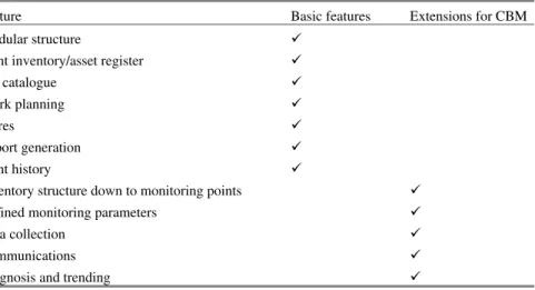
Table 2.2 Typical maintenance system features with integrated condition-based maintenance
Feature Basic features Extensions for CBM
Modular structure 9
Plant inventory/asset register 9
Job catalogue 9
Work planning 9
Stores 9
Report generation 9
Plant history 9
Inventory structure down to monitoring points 9
Defined monitoring parameters 9
Data collection 9
Communications 9
The standardisation of maintenance data was significantly advanced by MIMOSA, the Machinery Information Management Open Systems Alliance. MIMOSA standards are compliant with, and formed the informative reference to, ISO 13374-1 for machinery diagnostic systems (ISO 2002). Led by software house Entek and many condition monitoring technique providers, the interchange of data between proprietary systems became commonplace. The US Department of Defense took up MIMOSA standards in 2006, and large systems providers such as Invensys and SAP have worked with MIMOSA.
A wide range of software systems exist. Small-to-medium sized enterprises (SMEs) tend to implement simpler systems, but may benefit from a simplicity and clarity that eludes larger systems.
2.4.2 Limitations to the Penetration of Integrated Systems
It might have been expected that integrated maintenance systems would have al-most universal appeal, to all but the smallest customers, but some important prob-lems remain. The huge effort by MIMOSA started over 10 years ago to standard-ise interconnection with significant uptake by some specialist suppliers. Some key concepts, and connectivity between major system elements, are still the preserve of specialist sectors and providers. For example, computer-based systems starting from the perspective of enterprise resource planning (ERP) have only recently started to integrate the results of technical monitoring programmes for event initia-tion.
Clearly, the integration of large-scale systems is not trivial and takes a long time to achieve. The recognition of the important role of maintenance is still poor today, in many industries the focus is on new methods of production. An inte-grated maintenance system is technologically very complex and is not easy to in-tegrate. However, often there is also a desire to keep maintenance systems sepa-rate from production (e.g., control) systems, which is understandable because it may avoid risk to production, but on the other hand it may be a hindrance to effi-cient maintenance and reliability, which are prerequisites for production. It is pos-sible, therefore, that management structures that treat maintenance as a separate activity may also treat its systems separately, to the extent that it is not possible to integrate the systems structures. In such an organisation, the technical and mana-gerial systems and data will, therefore, be permanently disconnected from the company’s key business systems.
The forward strides in connectivity, facilitated by the internet and mobile tele-phone networks, have offered almost limitless scope to systems integrators. How-ever, users must continue to demand standardised systems interconnection, or spe-cialist suppliers will tie the user into proprietary arrangements, which ultimately fail to maximise the benefit to either party.
All software and data in complex systems carry their own maintenance cost. The effort involved with updating the software and data is a huge and demanding task. It is necessary to keep up with changes in the hardware, such as mass storage devices, systems software, such as new operating systems, and to apply normal changes to the system associated with, for example, changes to the plant supported by the maintenance system, such as a new piece of equipment.
2.5 State of the Art in Technology
2.5.1 Computing Tools
The use of computer systems is critical for the organisation of systems pertaining to maintenance. Section 2.2.3 considered the structure of maintenance software systems, but it is worth discussing briefly the hardware and firmware associated with practical maintenance systems. Low cost, pervasive computing tools, from the internet to the data stick, are readily adopted as part of systems solutions in maintenance. Maintenance practitioners have rapidly adopted highly mobile de-vices, with mobile internet connections, so that they can communicate with data-bases while on the move, either around a large plant or in many plants. Different solutions are adopted by employees of large companies and service providers to those companies. Local (wired) area networks are often inaccessible to mainte-nance staff because they belong to the host’s production function, so independent wireless communications are a distinct advantage. Maintenance practitioners also need access to normal business systems, e.g., email and internet, so they select the best proprietary solutions for both business and technical functions.
A key feature of maintenance systems is compatibility. In the past, mistakes were made in the selection of both hardware and software, leading to clumsy or impossible connections between technical systems and management systems. It is now a prerequisite that hardware and software not only be compatible now, but that legacy and future systems will connect as smoothly as possible. In maintain-ing engineermaintain-ing capital equipment, we expect a long life; therefore it is important that the design and installation data, the spare parts data, the service history and condition monitoring data are kept accessible, possibly for decades. We know that such systems will outlive computing devices and software versions. The current generation of lightweight PC notebooks, coupled with USB interfaces for hard-ware, and WiFi or 3G modem for internet, is capable of local processing and re-mote database access, but we can be sure that it will be superseded.
A major advantage of interconnecting, standard systems is that the specialist providers, of software, hardware and analysis, can concentrate on their core func-tions. For example, it is no longer necessary for a provider of multi-channel vibra-tion analysis to specify and build the data acquisivibra-tion hardware and computer
plat-form. Similarly it is not necessary to be concerned about the communication of actions arising from the vibration analysis, for example to raise a job to correct the source of the vibration. New systems provide functions, which were formerly only available in desktop computing, on a hand-held PDA (personal digital assistant).
Networking is particularly influential in the design of the state of the art for e-maintenance. The ubiquitous nature of the internet has changed our perception of how a network functions; it is no longer a proprietary connection for a specific purpose, tied to hardware, but rather it is used for all our information needs and is available by wireless almost anywhere. The question of security is answered by a range of standard technologies, for example encryption and secure server func-tions, used in credit card transactions. Many maintenance software systems host all their data on a web site to maximise accessibility; secure access is a straight-forward solution.
2.5.2 Measurement Tools and Services
Condition monitoring uses a range of methods to estimate the health of machines and processes, with the aim of confirming health or scheduling maintenance action prior to failure. This section briefly reviews some of the popular techniques avail-able, but there are many more techniques for specific measurement problems.
Monitoring of process parameters – sometimes the best indicator of the condition of a machine is its performance, e.g., pressure, flow rate and energy consumption of a pump. Unfortunately, robust machines can deliver normal performance up to a point very close to catastrophic failure, so specific measured parameters such as those below are adopted.
Vibration analysis measures the acceleration, velocity or displacement of moving mechanical components, sometimes directly, but more often at an available sur-face that gives an indication of internal events, without disrupting processes or containment. The vibration may lead to audible noise, excessive stresses and sub-sequent failures. Its measurement and analysis can detect a very wide range of common machine faults. The raw vibration data is typically processed into the fol-lowing:
• Overall vibration levels and levels of selected bands, consistent with known fault types.
• Frequency spectra and other analysis techniques seeking insight into many spe-cific faults; many specialised techniques are available for sophisticated diag-nostics, e.g., in turbines.
• High frequency emission for rolling element bearings, sometimes processed using event counting and thresholding, and sometimes simply banded.
Acoustic emissions (AE) measure the elastic waves passing through structures, and sometimes through the air, arising from events and continuous processes such as friction. Analysis of the strength and pattern of continuous and burst AE gives an early indication of faults in mechanical components and structures, with some im-portant capabilities for low speed machines, e.g., in bearings and gears at speeds below the capabilities of vibration analysis and large, loaded structures such as bridges and cranes.
Temperature monitoring – sensors of varying sophistication and cost can detect the temperature of electrical equipment, coolants, lubricants and mechanical com-ponents. Simple sensors measure specific points in, or on the surface of, a system. Infrared analysis – emissions in the infrared region of light are indicative of high temperatures. The equipment available for measuring the infrared emission usu-ally works in real time, so the dynamic changes can be examined immediately. The method is useful for locating “hot spots” over a wide physical area and can be used for the exterior of buildings, pipe work and ducting, mechanical systems and electrical/electronic systems. Sophisticated diagnostics can be conducted with thermal imaging over a wide area. Thermal imaging has made significant penetra-tion into new markets over the last ten years, with lower cost and with increasing expertise.
Lubricant analysis – the additives, contaminants and debris reveal the service condition of the lubricant itself, avoiding unnecessary oil changes, and also the level of wear particles from rubbing surfaces in the machinery. The technique is effective for slow moving and reciprocating machinery where vibration techniques are sometimes less effective.
Leak detection – methods from “soap and water” to ultrasonic and tracer gas tech-niques can detect minute leaks.
Corrosion monitoring – electrical resistance and potential techniques, hydrogen detection, sacrificial coupon and bore holes can be used to measure corrosion and its varying rates of progress during production runs.
Crack detection – many non-destructive testing (NDT) methods may be used for crack detection, e.g., dye penetrants, flux testing, and ultrasonics.
2.5.3 Portable Instruments
Most measurement processes benefit from real-time access to their measured envi-ronment, as opposed to sampling followed by laboratory measurement. In indus-trial environments, the access for large instrumentation and power supplies has always been limited, but “portable” implies that a trolley is no longer required. The benefit of small, self powered instruments is clear. However, portability is a
relative measure: a device that is too heavy to carry may still gain huge advantage by being packaged so that it can be moved out of a laboratory. Devices that are too large and heavy for aircraft may be quite acceptable on a ship.
Portable instruments generally carry a range of basic functions. Transducers have to be small enough to handle and must be powered by batteries for some hours. The simplest instruments have a very simple display, such as a meter or LED indicator, but typically we expect some local analogue and/or digital process-ing, followed by data storage and ability to transmit the data to a PC. Communica-tions can include wired and wireless upload and download, in a variety of stan-dards. Some instruments are equipped with significant power in digital signal processing (DSP). The versatility of such platforms means they may find applica-tion in many fields in science and medicine, as well as engineering.
Process parameters tend to be connected to existing monitoring systems, so they only need portable instrumentation in unusual circumstances. Most condition monitoring parameters are not connected to permanent systems, so they need port-able data collection.
Vibration analysis tends to use piezoelectric accelerometers, although other transducers are available. Input analogue electronics includes filters and amplifi-ers. Sampling is usually conducted at a high rate (up to about 50 kHz), prior to a range of DSP, but typically the fast Fourier transform, to produce a frequency spectrum. A range of post-processing can be applied for diagnostics. The raw sig-nals and spectra, and a range of other derived measurements, are stored. Display is typically a graphical array, up to full PC screen resolution, but often smaller, to save space. PDA devices, fitted with input electronics, can now offer similar ca-pability.
AE measurements use some of the same power supply, processing, communi-cation and display devices but need specific input electronics. Portable devices use analogue processing, in simple terms, to resolve burst events from background continuous emission and then to measure overall amplitude and severity.
Simple temperature devices are common. The time constants or lags associated with engineering equipment mean that slow measurements (in the order of 1 s) are sufficient. Hence the data collection and display is also simple. Thermal imaging requires much more sophisticated instrumentation. The camera is a typically a cooled charge couple device (CCD) array, which produces a high resolution image at a high data rate. The resolution tends to lag the typical television camera a little in terms of development, but the image can be at least 640 × 480 pixels, at a rate of 25 frames per second. Input electronics allow real-time contrast mapping to stretch or compress the display resolution across the temperature range of interest, achieving temperature sensitivity of up to 0.1°C. Frame and video sequence stor-age is then possible on typical video storstor-age devices. The technology has bene-fited directly from advances in domestic portable video devices, including its re-duction in size.
Lubricant and wear debris analysis are still emerging from the laboratory at the time of writing this. Portable devices are possible, but tend to require relatively
large transducers, including a wide range of fluid handling mechanisms and op-tics. There is no single technology that provides a universal measure for lubricant characteristics or wear debris features, so the benefits of mass production have less impact. The more popular measures, e.g., water in lubricant or fuel, have seen greater reduction in size of instrument. Larger instruments, e.g., particles counters, are “transportable”, their weight arises from high pressure sampling valves, ves-sels and pipe work. Sampling of fluids and particulates using magnets, filters and bottles is an important complementary alternative.
2.5.4 Laboratory-based Services
Many practitioners use the services of experts and laboratories. It is not always possible to develop low cost and portable instruments. The cost of the develop-ment is amortised only if sufficient goods can be sold. Some instrudevelop-ments are fun-damentally large, e.g., scanning electron microscopes or mass spectrometers. Laboratory-based services offer maintenance practitioners an industrial service using scientific principles. A very wide range of measurements is available, but as an example, the detail available in laboratory-based tribological analysis of wear debris far exceeds that available from portable methods
The cost of undertaking routine laboratory-based services can be quite reason-able compared to owning instruments and hiring staff. The sampling process has to be carefully managed, for example the data collection must avoid corruption, such as may occur in bottle sampling of fluids.
The return of measured data, with diagnostic and prognostic reports, has mi-grated to electronic format, and service organisations can return data in the correct format for direct uploading to the client’s own maintenance management system. MIMOSA compliance has been particularly important in this respect.
2.6 New Paradigms: Customisation and Sustainability
An important development in maintenance thinking is the business model of own-ership. In moving towards shared risk, the ownership of capital equipment can change. In order to produce a product or service, it is not necessary to own the equipment – it may be paid for in a range of methods and agreements. There is an increasing tendency for the manufacturers of equipment to retain ownership of their own products. Traditionally, manufacturers made money from selling spare parts. As we have seen from our examination of maintenance strategy above, re-placement of spare parts can be effective, but we would prefer to move to proac-tive and predicproac-tive maintenance, which will minimise the use of spare parts. If manufacturers own their own products, then they also wish to minimise the use of
spare parts. The focus moves to the maintenance of the service provided by the product. For example, the owner of a fleet of cars requires a specified transport service at a suitable cost. The car manufacturer is principally interested in selling new cars, and as a secondary concern, spare parts. However, if the manufacturer continues to own the cars, then the interest in spares is to minimise their use and cost.
Power plant manufacturers have been innovative in this regard. The complexity of diesel or gas turbine power plant is of little concern to the user. The current challenge is to make hybrid systems like combined heat and power, or increas-ingly renewable energy sourced power, not only as reliable as simpler power plant, but with the same level of convenience. Remote condition monitoring has ensured that a reliable service can be offered, without the need for the user to ac-quire specialist skills. Continued ownership of the plant has increased the innova-tion in supporting products in the field and underlined the importance of mainte-nance as an essential part of ownership.
The sub-contract of maintenance services has a similar model. Some of the most difficult condition monitoring problems are well served by this approach: integrated services for rotating machines, for example, now include provision of specialist bearings, lubrication and monitoring services. This means that a paper producer, for example, can concentrate on making paper, instead of managing the replacement of bearings and lubricants. The rollers in the paper machine are still required to be located with minimum friction, so the integrated service can con-centrate on providing that function.
Life cycle costing is not yet universal, and it has been observed that the reason is that the average lifetime of capital equipment considerably exceeds the average period-of-office of a CEO! Notwithstanding this truism, the cost of maintenance is now regarded as a major input to investment decisions. The costs of energy and maintenance far outweigh the initial purchase price in many situations. Hence the maintenance of equipment and the monitoring of its operating efficiency will be major contributors to sustainability.
The idea of a standard product is also changing. The biggest problems in main-tenance do not arise from mass-produced items, but from bespoke ones. In the maritime sector, for example, where preventive maintenance is critical, the nature of small production runs and mobile assets means that spare parts are a special problem. They are frequently heavy and bulky, and parts must be held in strategic ports worldwide or on board the ship. Unlike vehicles that are manufactured by a handful of companies in long production runs with standardised components, ships are built to many specialised designs in small numbers by shipyards all over the world with little commonality. In the commercial marine sector alone the Lloyd’s Register/Fairplay database lists 160,000 vessels above 100 gross tonnes. The average age of the world’s fleet is around 18 years. Consequently, the avail-ability of spare parts is a constant global challenge.
The mobility of expertise, and the sub-contract or outsourcing of skills, is con-siderably enhanced by e-maintenance. Clearly, the initial building of good
rela-tionships is still fostered by face-to-face meetings, but electronic communication allows the rapid transfer of documents, data, images, video, software updates and training. This means that expertise can be mobile across continents and time zones, and can have global impact. With highly mobile assets such as ships and land vehicles, which may have relatively low skilled crews, the outsourcing of maintenance and repair activity is common. The work is undertaken by local re-pair companies, specialist maintainers and technologists, and so-called “flying crew”, highly-skilled specialists who are temporarily transported to the site.
A major future influence will be the contribution that maintenance makes to sustainability. The concept of life extension, and maximising reliability at mini-mum cost, is the bread and butter of maintenance, and such efforts add genuine competitiveness to businesses. However, the new challenge of our time is carbon reduction. The carbon cost of engineered systems is high during their lifetimes, comprising the embedded carbon of manufacturing and the carbon used during operation. Maintenance has significant contributions to make, by avoiding unnec-essary replacement and by supporting efficient operation (Starr et al. 2007).
2.7 New Developments in Decision Making
Decisions in industrial maintenance involve risks to equipment, expenditure and personnel, and yet they are based on inaccurate data. Technical inputs such as es-timates of machine health, using sophisticated measurements and signal process-ing, must be combined with vague information about risk and cost, in a dynamic assessment aimed at an optimal long term outcome such as maximum reliability or minimum cost. The decision is typically in the hands of a human, who must weigh technical risk against limited resources, taking into account physical limitations, the requirements of the law, and the “political” implications of the conflicting de-cisions. Research work aims to provide automated assistance in the decision mak-ing process by usmak-ing data fusion methodology to combine dissimilar quantities and information, and by coping with missing data. The computed recommendations are aimed at the human, who must remain in control of the process (Esteban et al. 2005).
The problem is a top-level decision, which draws on lower-level data fusion problems, converting data to information and then to decisions, and which might combine measured data and knowledge. The problem has several areas of uncer-tainty:
• The technical alert has varying degrees of confidence and urgency, usually un-known in the field.
• The cost data may be difficult to obtain or may be out of date.
• The criticality or risk data may be difficult to obtain, out of date or invalid for the current equipment arrangement.
Combination of the three input streams, based on cost-based criticality, pro-duces a ranking based on the risk of expenditure. The ranking is optimised to minimise consequential cost. The method provides an audit trail for decision-making, which is important in many industrial sectors (Moore and Starr. 2006).
2.8 New Developments in Technological Tools
Maintenance benefits from a wide range of technologies, which have often been developed for a different purpose. A number of new off-the-shelf tools are de-scribed below, which are likely to create significant advances, including wireless sensors, miniaturisation and MEMS (micro electro-mechanical systems), a range of new disruptive technologies, and pervasive sensing and intelligence.
2.8.1 Wireless Sensors
Wireless communication is experiencing explosive growth in many areas of elec-tronics, and it is clear that there are some fundamental advantages in shedding both the cables and the plugs associated with conventional communications. The cost of devices for consumer electronics, such as mobile telephones, toys and computer peripherals, has plummeted. Distributed wireless monitoring is now a reality and it is developing fast.
The systems architecture of a wireless sensor is the starting point. There are parallels with, and distinct differences to, older portable devices used for monitor-ing and diagnostics, as shown in Table 2.3.
Low cost changes the thinking in design (Albarbar et al. 2007). Multiple meas-urands are possible and desirable in a wireless sensor. Connectivity is critical, as part of the wider e-maintenance network. Commercial off-the-shelf (COTS) radio platforms offer high functionality, integration, and low cost, exploiting radio stan-dards such as Bluetooth (IEEE 802.15.1) and Zigbee, an extension to IEEE 802.15.4, which is specially intended for sensors (Pietruszkiewicz et al. 2007). Size, processing and power supplies are developing rapidly. The sensor’s internal processing capacity is capable of accommodating basic diagnostic functions, trending, prognosis and decision making, and communicating health status indica-tions.
The software for performing remote, automated, distributed monitoring, in a robust fashion without recourse to human intervention, remains a challenge for the success of such a system. The embedding of knowledge and procedure will be im-portant for the penetration of the new devices into the unmanned monitoring of future applications.
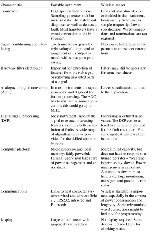
Table 2.3 Characteristics of portable instruments and wireless sensors
Characteristic Portable instrument Wireless sensor Transducer High specification sensors.
Sampling generates rich but massive data. The instrument diagnoses as well as detects a fault. Most transducers have a wired connection to the in-strument.
Low cost miniature devices embedded in the instrument. Permanently fixed, so can sample frequently. Lower specification. Wired connec-tions and terminaconnec-tions are not required.
Signal conditioning and inter-facing
The transducer requires the right voltage(s) input and ar-rangement of its output to match with subsequent proc-essing.
Necessary, but tailored to the permanent transducer connec-tions
Hardware filter electronics Important for extraction of features from the rich signal or removing unwanted parts of a signal
Filters may still be necessary for some transducers
Analogue to digital conversion (ADC)
In most instruments the signal is sampled and digitised for further processing. The ADC has to run fast: in some appli-cations this could go up to MHz.
Lower specification, tailored to the application.
Digital signal processing (DSP)
Most instruments modify the signal to extract interesting features, enabling better reso-lution of faults. A wide range of algorithms may be pro-vided for the skilled operator to apply.
Processing is defined in ad-vance. The DSP can be tai-lored to a minimum required for the fault resolution. For some applications it will not be required.
Computer platform Micro processor and local memory; fairly powerful. Human supervision takes care of power management and er-ror states.
More limited capacity, but does not have to respond to a human operator – “real time” is permissibly slower. Power management is important. Automatic software must handle start-up, monitoring, messages, and potential error states.
Communications Links to host computer sys-tems: wired and wireless links
e.g., RS232, infra-red and Bluetooth
Wireless standard is impor-tant, especially in the context of power consumption and longevity. Some miniaturised wired connections might be included for programming. Display Large colour screen with
graphical user interface
No display required. Some devices include LEDs for checking status.
Table 2.3 (continued)
Characteristic Portable instrument Wireless sensor Packaging A substantial box suitable for
industrial conditions; strong terminals for the electronic connections
The device only needs simple protection from the environ-ment. Contact of the transduc-ers with surfaces is important in some cases.
Battery Rechargeable or long-life cells, housed within the pack-age. Recharging or replace-ment is practical.
Power management is critical. Wired recharging is not prac-tical. Renewable sources are a practical proposition. Operating conditions Human operator makes most
instructions.
Operates autonomously most of the time.
Diagnosis requirements Detailed information Simple fault detection, moni-toring and alerting
Cost Up to €10k depending on package
Up to €100, but tending to re-duce – “disposable”
2.8.2 Miniaturisation, Cost Reduction and MEMS
Miniaturisation can be simply defined as smaller than the last attempt; it is a rela-tive measure. The reduction in size, with corresponding power requirements, is familiar in many walks of life. Computing, for example, has reduced from a room-full, to a box, to a laptop, and now to a pocket-sized device. One manufacturer has promised a holographic keyboard, and USB data sticks have reduced to the size of a postage stamp. Almost every device used in maintenance has reduced in size; there are, however, some human limitations. Display devices, such as screen and meters, need to be big enough to read, key pads need to be large enough for fin-gers, sometimes wearing gloves. In some industries, the favoured package for sen-sors has taken impact and other abuse into account, even if the transduction ele-ment is tiny. The reliable electrical connection has depended on relatively large connectors and cables, even for tiny signal currents. The use of wireless devices has made considerable advance in package size; if signal connections are no longer necessary, a large contribution to mass and volume is removed. The next challenge is the reduction in size, and removal of connections, for replaceable bat-teries, with local “power harvesting” as the alternative.
A critical part of size reduction is also cost reduction. Some materials and processes only become viable in a large quantity, and the maintenance sector has often benefited from a technology advance, when it has had a more popular appli-cation. Distinctly different decisions are made between capital equipment, even at the low cost end, and consumable items. Devices that are disposable may have very different expectations in life, target applications, packaging, selection of
ma-terials and technology choice. However, the acceptable price of a disposable item can be surprisingly high in some industries. This means that the threshold for budgeting influences the strategic decisions for sensor architecture in many appli-cations. If the price is acceptably low, short life is acceptable; light weight packag-ing, coupled with battery power, can allow access to measurement problems that would be inaccessible to expensive, longer life solutions. Multiple low cost sen-sors can allow access to highly-resolved measurements over a wide area, with lo-cal communication between sensors. Damage to, or loss of, a sensor is of little consequence, so higher risks are acceptable to such a measurement system.
MEMS have seen a great deal of development in recent years, and many prod-ucts are now on the marketplace (Nexus 2009). The key advances are in the minia-turisation of the transduction elements, in the measurement of, e.g., strain, pres-sure, acceleration, angular rate, displacement, force, ultrasonics, flow, temperature, optoelectronic photonic properties and magnetic properties, amongst others. Some packages of MEMS sensors include multiple transducer elements, for different parameters, on the same substrate. The advantages of MEMS lie in the size and unit costs of mass-produced items; for example, the ADXL105 accel-erometer measures about 10 × 8 × 4 mm and can be configured to work up to about 10 kHz with sensitivities of 250 to 1000 mV/g and temperature measure-ment, at the cost of a few Euros. The extra functionality offered by local process-ing, either in the package or in associated circuitry adds a real boost to “smart” sensing. However, the power and communications requirements still provide some constraints. Transducers are generally already small; it is the packages and con-nectors that are large. Reducing the size of the transducer alone is not sufficient to reduce the size of the whole package.
Overall, size reduction is a relative measure: what is large in a car or an aircraft may be very small on a ship. We can be certain, however, that technological de-velopments in related fields will continue to offer further size reduction in mainte-nance devices.
Albarbar reported the details of the transducer selection and signal conditioning (Albarbar et al. 2007). The work investigated a range of low cost sensing elements at component level, for integration with the COTS platform. The requirement for temperature, pressure and vibration has led to testing of a variety of piezo and MEMS devices. The mass production of such devices has offered high quality at low cost, but requires some expertise to interface the devices and to mount them in suitable packages. The wireless sensor does not need to be handled, so the pack-age does not have to be excessively robust.
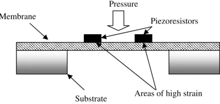
The basic construction of a piezoresistive pressure micro sensor, using a flexi-ble silicon membrane as the sensing element, is shown in Figure 2.3. MEMS ac-celerometers are generally divided into two main types: piezoresistive and capaci-tive-based accelerometers. The schematic of a piezoresistive MEMS accelerometer is shown in Figure 2.4 (Plaza et al. 2002). These accelerometers generally consist of a proof-mass suspended by a “spring”, which in MEMS is usually a cantilever or beam. When the device is subjected to acceleration, the
in-ertia of the mass causes changes in the gap between it and the bulk of the device. Vibration sensors can operate using the same principle (Partridge et al. 2000). The mass may move out of the plane of the silicon wafer or in the plane (as is common in surface micro machined devices) (Xie et al. 2000). The piezoresistive acceler-ometer incorporates a piezoresistor on a cantilever beam structure, as shown in Figure 2.4. The electric signal generated from the piezoresistive patch and the bulk device due vibration is proportional to the acceleration of the vibrating object. Ca-pacitive-based MEMS accelerometers measure changes of the capacitance be-tween a proof mass and a fixed conductive electrode separated by a narrow gap.
Figure 2.3 Piezoresistive pressure micro sensor based on membrane structure
Figure 2.4 Typical piezoresistive micro accelerometer using the cantilever design
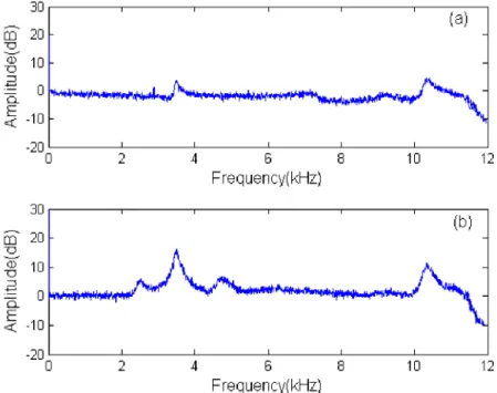
The results from a calibration test of the transfer function of a MEMS acceler-ometer and an integrated circuit piezoelectric (ICP) acceleracceler-ometer are of interest. Figure 2.5 illustrates graphically the response from 0–12 kHz, under test on a shaker driven with white noise and compared to a conventional B&K piezoelectric accelerometer (Albarbar et al. 2007, 2009). Note the peaks at 3.7 kHz, probably associated with the mounting assembly, and at 10.5 kHz, a resonance above which
Vibration
Substrate
Piezoresistors
Cantilever
Base Proof mass Pressure
Areas of high strain Substrate
the signal dies away fairly rapidly. Given the typical running speeds of electrical and mechanical machines, these bandwidths allow access to most of the features of interest in fault detection. Note that these bandwidths were achieved by stiff mounting direct to a metal surface screwed to the shaker.
Figure 2.5 Transfer function for: (a) MEMS, and (b) ICP accelerometers
2.8.3 Disruptive Technologies and the Future
A disruptive technology is one that changes the game; for example, internet trad-ing has changed the way we do business, forever. Maintenance management and technology has benefited hugely from several disruptive technologies, even if they were intended for completely different target audiences, e.g., personal computing profoundly changed the nature of maintenance management software and its up-take.
The ability to predict the future is perhaps restricted to fortune-tellers, but the authors claim some knowledge of condition monitoring prognostics, which is in a similar vein! In this section it is our purpose to make some speculative remarks about the possible influencing technologies and ideas that may change the way in which we do maintenance in the future.
Nanotechnology has flooded the research literature and popular airwaves, with some questionable advances and speculative claims. Events at a nanometre scale are already of great interest to maintenance practitioners but they are difficult to measure: fracture mechanics, considering the sub-surface cracking in bearing sur-faces; lubricant properties, such as metallic particulate and additives. Of particular interest is the spherically-structured Buckminster Fullerene C60, which has al-ready been evaluated as a dry lubricant by NASA and academic laboratories. The carbon nanotube structure is also likely to lead to interesting lubricant properties. Nanostructures are also likely to provide structures, e.g., for the delivery of addi-tives to extreme conditions over a long period, with a strong connection with medical applications. Many biological structures are measured in nanometres, and the ability of using tiny structures as treatments and tell-tale evidence of wear, or of some other physical interference, e.g., of mechanical seals, may prove success-ful.
Algorithms:The ability to judge a good measurement or decision, from a bad one, is a major challenge for maintenance practitioners. The raw data is influenced by a very wide range of interference and uncertainty. Researchers expend great effort to improve such numerical estimation and classification problems, but the solu-tions are hard to implement. Algorithms that have been demonstrated on super-computing platforms in the past, e.g., genetic algorithms were demonstrated by NASA in the 1950s, can now be executed on a typical PC, and with a bit of pa-tience, on sensor and mobile telephone platforms. Moore’s law suggests that proc-essing power doubles every year; hence the ability to have whatever procproc-essing you require, in “real time” (i.e., fast enough), will be achieved sooner or later (Schaller 1997). What remains is the choice of the right processing for the job: numerical problems do not all yield to neural networks, and classification prob-lems do not all yield to knowledge-based systems. A good deal of learning will be necessary to implement the solutions required, but there will be no shortage of dis-tributed processing capability. An analogous example is the JPEG algorithm for photographic compression; it is so good and so ubiquitous that we forget its pres-ence and can no longer remember being without it (ISO 1992). In the future we may regard the Fourier spectrum as an ancient precursor of multi-dimensional data-mining displays, given that Fourier died in 1830 and the fast Fourier trans-form was built into hardware almost 50 years ago. On a smaller scale, smart sen-sors with automatic alarms are already with us. There are, of course, new risks in using methods with which we are not familiar; human supervisors of automated systems have to be wary of false alarms. Image processing algorithms will almost certainly make an impact in condition monitoring; many sensors already produce multi-dimensional data, some of which is a clear picture (e.g., thermal images, wear debris particulate micrographs), some a reconstructed picture (e.g., scans from non-destructive testing, such as ultrasonic thickness testing) and some of which is multi-dimensional mapping, not a picture (e.g., waterfall plots or wavelet transforms). Most of these data forms will be difficult to interpret and will need