VYSOKÉ UČENÍ TECHNICKÉ V BRNĚ
BRNO UNIVERSITY OF TECHNOLOGY
FAKULTA ELEKTROTECHNIKY
A KOMUNIKAČNÍCH TECHNOLOGIÍ
FACULTY OF ELECTRICAL ENGINEERING AND COMMUNICATION
ÚSTAV TELEKOMUNIKACÍ
DEPARTMENT OF TELECOMMUNICATIONS
IMPLEMENTACE SLUŽBY VOLTE DO SÍTÍ
EPS-IMS
VOLTE SERVICE IMPLEMENTATION IN EPS-IMS NETWORKS
DIPLOMOVÁ PRÁCE
MASTER'S THESISAUTOR PRÁCE
AUTHORBc. Mikhail Baev
VEDOUCÍ PRÁCE
SUPERVISORdoc. Ing. Vít Novotný, Ph.D.
2
ANOTACE
Diplomová práce popisuje VoLTE službu, vývoj a nasazení LTE (zaváděcí fázi, skutečný LTE stav a výhledy do budoucna atd.), EPC-IMS architekturu (popis funkce uzlu, rozhraní atd.) Komunikace mezi uzly a funkce, rozhraní a protokoly jsou používány v průběhu signalizace (SIP SDP) a datový tok (RTCP RTP). Práce stručně popisuje základní toky hovorů, typy nosičů (GBR and N-GBR), a to vytvoření / mazaní nosičů během komunikace. Další část diplomové práce o implementaci volte, instalace a konfigurace IMS. Závěrečná část diplomové práce popisuje zkoušky sítě a, analýzu protokolu.
KLÍČOVÁ SLOVA
VoLTE, Call flow, IMS, EPC, CSCF, HSS, mobile network, SIP, SDP, RTCP, RTP
ABSTRACT
The master's thesis describes VoLTE service, LTE evolution and deployment (deployment phases, actual LTE state and future perspectives etc.), EPC-IMS architecture (functional node description, interfaces etc.). Communications between nodes and functions, interfaces and protocols which are used during signaling (SIP-SDP) and data flow (RTCP RTP). Thesis briefly describe basic call flows, bearers types (GBR and N-GBR) and their establishment/delete during communication. The next part of master's thesis is about VoLTE implementation solutions, IMS installation and configuration. The final part of master's thesis describes the network and protocols tests, analyzes.
KEYWORDS
3
Baev, M. Volte service implementation in EPC-IMS networks: diploma thesis. Brno: FEKT VUT v Brně, 2016. 56 pages, 3 appendices. Supervisor doc. Ing. Vít Novotný, Ph.D.
4
Prohlášení
Prohlašuji, že svou diplomovou práci na téma „IMPLEMENTACE SLUŽBY VOLTE DO SÍTÍ EPS-IMS“ jsem vypracoval samostatně pod vedením vedoucího diplomové práce a s použitím odborné literatury a dalších informačních zdrojů, které jsou všechny citovány v práci a uvedeny v seznamu literatury na konci práce.
Jako autor uvedené diplomové práce dále prohlašuji, že v souvislosti s vytvořením této diplomové práce jsem neporušil autorská práva třetích osob, zejména jsem nezasáhl
nedovoleným způsobem do cizích autorských práv osobnostních a/nebo majetkových a jsem si plně vědom následků porušení ustanovení § 11 a následujících zákona č. 121/2000 Sb., o právu autorském, o právech souvisejících s právem autorským a o změně některých zákonů (autorský zákon), ve znění pozdějších předpisů, včetně možných trestněprávních důsledků vyplývajících z ustanovení části druhé, hlavy VI. díl 4 Trestního zákoníku č. 40/2009 Sb.
V Brně dne ………. ... podpis autora
5
Poděkování
Děkuji vedoucímu práce doc. Ing. Vítu Novotnému, Ph.D za velmi užitečnou metodickou pomoc a cenné rady při zpracování diplomové práce.
V Brně dne ……….. ... podpis autora
6
The research described in this diploma thesis has been done in laboratories supported by Sensor, Information and Communication Systems Research Centre (SIX) project; registration
number CZ.1.05/2.1.00/03.0072 Operational Program Research and Development for Innovation (operační program Výzkum a vývoj pro inovace).
Faculty of Electrical Engineering and Communication
Brno University of Technology
Technicka 12, CZ-61600 Brno, Czechia http://www.six.feec.vutbr.cz
7
Contents
Introduction ... 9
LTE ... 10
2.1 Evolution and deployment ... 10
2.2 LTE characteristics and goals ... 11
VoLTE architecture ... 12
3.1 UE ... 12
3.2 Evolved Universal Terrestrial Access Network – E-UTRAN architecture ... 12
3.3 Evolved packet core (EPC) architecture ... 13
3.3.1 Functions and nodes ... 13
3.3.2 Interfaces ... 14
3.3.3 Protocols ... 15
3.4 IP multimedia subsystem (IMS) architecture ... 16
3.4.1 Functions ... 16
3.4.2 IMS interfaces description. ... 19
3.4.3 IMS protocols ... 22
VoLTE service requirements ... 25
4.1 Adaptive Multi-Rate (AMR) Speech Codec ... 25
4.2 Robust Header Compression ... 25
4.3 LTE Radio Capabilities ... 25
4.4 RLC configurations ... 27
4.5 Guaranteed bit rate (GBR) bearer ... 27
4.6 P-CSCF Discovery ... 28
4.7 Addressing ... 29
4.8 Handovers ... 29
The basic call flows scenarios ... 30
5.1 Attachment and IMS Registration ... 30
5.1.1 Default Bearer establishment for attach to IMS ... 30
5.1.2 IMS registration ... 33
5.2 Basic VoLTE UE to VoLTE UE Voice Call Establishment ... 36
5.2.1 Originating Side ... 36
5.2.2 Terminating Side ... 40
8
5.3.1 Initiated side ... 43
5.3.2 Received side ... 44
Tests on LTE network ... 46
6.1 EPC attach UE – eNodeB - MME ... 46
VoLTE implementation analyze and solution ... 48
7.1 IMS install ... 48
Conclusion ... 50
Literature ... 51
9
Introduction
Modern networks are developed for providing higher data rates for subscribers. Implementation of new and expand of the existing technologies are needed. In cellular
communication, actual step in evolving is implementation Voice over IP to 4G mobile networks. In the specification 4G LTE by the 3rd Generation Partnership Project (3GPP) in release 8, it was designed as a pure packet switched system and either data services and real time services would be carried by the IP protocol. However, 3GPP formally announced VoLTE in February 2010 and GSMA announced “VoLTE Service Description and Implementation Guidelines” in October 2014. During this time mobile communications service providers (CSPs) is necessary to use solutions to move a subscriber from LTE to a legacy technology to obtain circuit switched voice service – CSFB (circuit switched fallback). During fallback data rate is decreased because of using legacy data services too, for example GPRS, EDGE or HSDPA. In addition, handover to latest generations increased call setup time twice.
Supporting voice over IP in a cellular communication system brings new challenges. Voice support in LTE requires the right mechanisms and architecture in radio and core networks, to guarantee quality of service and a good user experience because subscribers expect the same quality of service they know from circuit switched voice services, in GSM networks for example. Even after moving the voice services to VoIP, mobility between 4G and the previous cellular network generations is still the key problem.
The main task of this master thesis is:
1) Review the mobile system EPS and subsystem IMS, focus on the voice services and compare currently used solutions.
2) Analyze the issue of deployment of VoLTE services in Department of telecommunications to their experimental EPS-IMS network, and describe particular solution.
3) Like addition execute several VoLTE sessions, realize handover, capture and analyze it. 4) Suggest the laboratory exercise for MKPM course
The most important step is analyzing VoLTE architecture to understanding nods, functions and interfaces functionality in complex. It was the key to find the better theoretical solution. The experimental LTE network on facility was in Phase one LTE implementation.
10
LTE
2.1
Evolution and deployment
Now 4G LTE is a newest mobile solution in the market. 3GPP evolution starts in 1999, when original UMTS was release. Then the other technologies was release that are using in 4G LTE:
Year Release Technology
1999 R99 Original UMTS
2000 R4 Basics of IMS
2001 R5 HSDPA, complete design of IMS
2002 R6 HSUPA, support for multimedia
2004 R7 HSPA+, MIMO
2007 R8 Defines the LTE and transition
2008 R9 Further enhancements of LTE
2011 R10 LTE Advanced
2013 R11 Continue of LTE Advanced – advanced interconnection between cervices
Table 2.1 3GPP evolution of technologies (1)
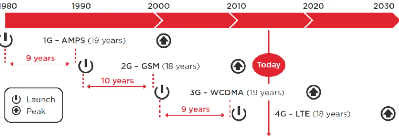
Historically, cellular technologies have adhered to an approximate 20-year cycle from launch to peak penetration, with around ten years between the launch of each new technology (see Figure 5). The first commercial LTE networks went live in 2009 and based on historical
precedent we would not expect the technology to reach a peak level of connections until around 2030.
These technologies are used to develop the final version of 4G LTE and deploying in three phases:
LTE Phase 1 – implementation EPC with oldies generation mobile networks. Uses for data services only.
LTE Phase 2 – voice implementation within 3G/2G – Circuit Switched Fall Back (CSFB). LTE Phase 3 – Voice over LTE (VoLTE). Final phase, all mobile services handled by LTE network. Description of VoLTE released by GSM association (GSMA) in “VoLTE Service Description and Implementation Guidelines” in 2014. (2)
11
2.2
LTE characteristics and goals
Improved performance
Efficient use of radio spectrum: UMTS had ~3 bps/Hz spectral utilization, LTE had 15 bps/Hz.
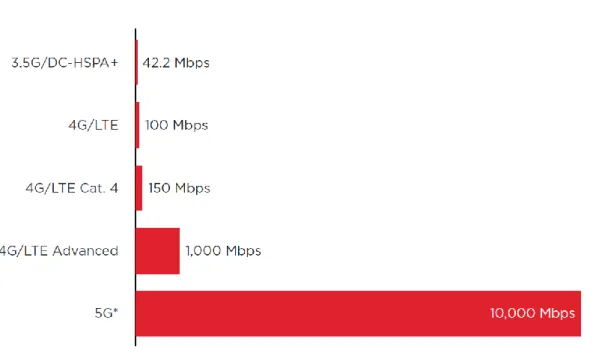
High data rates: 100 Mbps downlink, 50 Mbps uplink
Low latency: 10 ms and less, idle to activate transition under 100 ms
Reduced costs
Simplified architecture, minimum configuration. Only packet switched services was support, data services were shift away from 3G, leaving more capacity for Voice services in 3G.
Less components delivering more services Increased Value
Better user experience
Allow access to services anytime, anywhere
Figure 2.2 Maximum theoretical downlink speed by technology generation, Mbps (*10 Gbps is the minimum theoretical upper limit speed specified for 5G) (20)
12
VoLTE architecture
The VoLTE logical architecture is based on the 3GPP defined architecture and principles. The main functional nodes of the VoLTE architecture are described below
3.1
UE
The VoLTE user equipment was use to connect eNB via the LTE-Uu radio interface. Other access technologies may also be supporting by the UE.
3.2
Evolved Universal Terrestrial Access Network – E-UTRAN
architecture
E-UTRAN based on the “Flat architecture”, that allow to eliminates centralized controllers like RNC or BSC, and consist of a single node, the eNodeBs (eNB).
For pooling resources, each eNB was connect to multiple MMEs and SGWs, that covering same geographical area. All–IP design – allow to delivering all services over the same
infrastructure. Interfaces:
S1mme – signaling S1u – user data packets
eNodeB’s interconnected via X2 interface. It allows eNB to connect directly, separated into control and user plane. If X2 interface available between two neighbor eNodeBs, this interface managing to handover within Mobile Management Entity (MME). Similar to S1u use GTP to carry user traffic.
eNB functions: E-UTRAN EPC S1-U eNodeB eNodeB UE LTE-Uu MME SGW X2 S1-MME S1-MME S1-U Figure 3.1 E-UTRA
13
Radio Resource Management (RRM) include radio bearer control and radio admission control
IP header compression and user data encryption
Uplink and downlink resource scheduling
Transmission of paging messages and broadcast information
Selection of MME
Measurements (quality, performance)
Routing of user data to the S-GW
LTE radio access network RAN are based on OFDMA orthogonal frequency-division multiple access and MIMO (multiple-input and multiple-output) technologies.
OFDMA goals:
Scalability – able to utilize variable bandwidth
Time and frequency scheduling – radio resources can be allocated over multiple channels and/or multiple transmission symbols
Reduced interference – channels don’t interfere
Higher data rates – OFDM have plenty of channels and user can get multiple assigned
MIMO support
In a difference of FDM, OFDM have not guard bands, which save bandwidth
3.3
Evolved packet core (EPC) architecture
3.3.1
Functions and nodes
MME – Mobility Management Entity is the key control-node for the LTE access network. It is
signaling node only – not involved in user traffic. MME responsible for functions related to UE mobility:
Managing and storing UE contexts
Generation and allocation of temporary UE IDs
Evolved Packet Core
E-UTRAN 2G/3G UTRAN
SGSN MMEMMEMME
SGW PGW DRA S6a HSS S1u S1mme S5 PCRF Rx S11
14
Idle state mobility and roaming
Security functions (authentication, authorization)
Bearer path control (S-GW and P-GW selection)
MME provides the control plane function for mobility between LTE and 2G/3G access networks and interfaces with the home HSS for roaming UEs.
Support for other call control and session management entities
Home Subscriber Server (HSS) – network master database, which holds user subscription
data (ID, numbering and service profiles) and provide authentication and authorization to the MME and IMS core during UE attach and IMS registration.
Packet Data Network Gateway (PGW) – default router for UE. Provide IP address allocation.
Support policy and charging enforcement (PCEF), packet filtering for each user and performs marking for QoS management. UE may be connect to multiple PGW for accessing multiple Packet Data Networks. May coexist on same physical platform with SGW.
Serving gateway (SGW) routing and forwards packets between PGW and E-UTRAN,
anchoring user plane during inter eNB handovers and as the anchor for mobility between LTE and other 3GPP technologies. Providing support for lawful interception. UE connected to one SGW.
Police and Charging Rules Function (PCRF) provides policy control decisions and flow based
charging controls. Support for QoS in EPC network ensure that the user’s plane traffic mapping and treatment is in accordance with the user’s profile. Connected to PGW that implements policy and charging enforcement function (PCEF).
Diameter Relay Agent DRA is a function specialized in forwarding Diameter messages,
provide roaming to other LTE networks. Support for more MMEs and HSSs. (3)
3.3.2
Interfaces
S1 interface connects E-UTRAN to EPC.
S1u – user plane: using GPRS Tunneling Protocol (GTP) on UDP. May be only one GTP tunnel
per radio bearer. For QoS assigns level of service and priority to each packet used Differentiated Services Code Point (DSCP).
S1mme – Control plane interface between EUTRAN and MME. Carries S1 Application
Protocol (S1AP) messages. Handle EPS bearer (setup and release), paging, NAS and handover signaling. For guaranteed data delivery over IP using Stream Control Transmission Protocol (SCTP), each SCTP association can support multiple UE. Provides redundancy and load sharing.
The S5 interface provides user plane tunneling and tunnel management between SGW and PGW. The SGW and PGW may be realize as a single network element in which case the S5 interface is not exposed. (2)
The S6a interface enables the transfer of subscription and authentication data for
15
The S10 interface provides for MME – MME information transfer and was use to enable MME relocation. The protocol used on the S10 interface is GPRS Tunneling Protocol-Control plane (GTPv2-C). (2)
The S11 interface is between the MME and S-GW to support mobility and bearer
management. The protocol used on the S11 interface is GPRS Tunneling Protocol-Control plane (GTPv2-C). (2)
The Gx interface is between the PCRF and the PGW, allowing the PCRF direct control over the policy enforcement functions of the PGW. The protocol used on the Gx interface is Diameter. (2)
3.3.3
Protocols
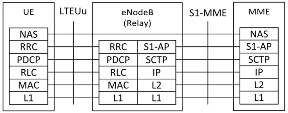
The Non-Access Stratum is a set of protocols in the Evolved Packet System. The NAS is used to convey non-radio signaling between the User Equipment (UE) and the Mobility Management Entity (MME) for an LTE/E-UTRAN access. (4)
Initiating and maintaining EPS bearers
UE registration
Moving S1 and radio bearers during mobility
Carried over S1mme
User plane protocols using GTPv1 on all interfaces. X2AP – tunnels between eNBs during inter-eNB mobility
S1AP is the S1 application protocol between the EUTRAN and MME.S1AP provides bearer
management. Was use to establish an S1UE context in the eNB, to setup the default IP connectivity. (5) UE eNodeB (Relay) MME NAS RRC PDCP MAC L1 RLC NAS S1-AP SCTP L2 L1 IP LTEUu RRC PDCP MAC L1 RLC S1-AP SCTP L2 L1 IP S1-MME
16
3.4
IP multimedia subsystem (IMS) architecture
IMS is the control infrastructure for supporting next generation IP Multimedia Services and consists of many separate elements.
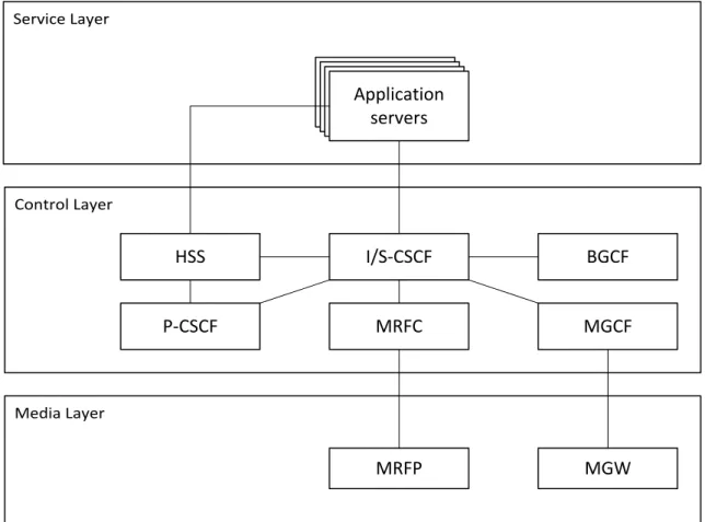
Logically IMS can be divide by functional layers:
1. Control layer provides manage the session control, authorization, call routing and billing. The S-CSCF is the main call control element.
2. Service layer provides specific services (including telephony) implemented by Application Servers (AS). Once S-CSCF invokes a service, the AS can control the processing of the session
3. Media layer. Media processing – announcements servers, conference bridges, media servers – this layer is under control of the other two layers. Media Gateways are responsible for codec conversion. MGCF is physically implemented in 3G MSC
3.4.1
Functions
The Call Session Control Function (CSCF) may take on various roles as used in the IP multimedia subsystem. The following sections describe these various roles.
The Proxy-CSCF (P-CSCF) is the first contact point within the IM CN subsystem. Its address is discovered by UEs following PDP context activation, using the mechanism described in section “Procedures related to Local CSCF Discovery ”. The P-CSCF behaves like a Proxy (as defined in
Service Layer Control Layer Media Layer Application servers Application servers Application servers Application servers HSS I/S-CSCF P-CSCF MRFC BGCF MGCF MRFP MGW
17
RFC2543 or subsequent versions), i.e. it accepts requests and services them internally or forwards them on, possibly after translation. The P-CSCF may also behave as a User Agent (as defined in the RFC2543 or subsequent versions), i.e. in abnormal conditions it may terminate and independently generate SIP transactions.
The Policy Control Function (PCF) is a logical entity of the P-CSCF. If the PCF was implement in a separate physical node, the interface between the PCF and the P-CSCF is not standardized.
The functions performed by the P-CSCF are:
1. Forward the SIP register request received from the UE to an I-CSCF determined using the home domain name, as provided by the UE.
2. Forward SIP messages received from the UE to the SIP server (e.g. S-CSCF) whose name the PCSCF has received as a result of the registration procedure.
3. As part of processing of the request and before forwarding, the P-CSCF may modify the Request URI of outgoing requests according to a set of provisioned rules defined by the network operator (e.g. Number analysis and potential modification such as translation from local to international format.)
4. Forward the SIP request or response to the UE.
5. Detect an emergency session and select a S-CSCF in the visited network to handle emergency sessions. Interrogating – CSCF – is responsible for determining with which S-CSCF is the UE registered. The main functions of the I – CSCF are Select the S – CSCF during registration and load balancing across the S – CSCF.
Authorisation of bearer resources and QoS management. Details of the P-CSCF role in QoS management and authorisation of bearer resources for the session are being investigated by the QoS ad-hoc group. (6)
Interrogating-CSCF (I-CSCF) is the contact point within an operator’s network for all
connections destined to a subscriber of that network operator, or a roaming subscriber currently located within that network operator’s service area. There may be multiple ICSCFs within an operator’s network.
The functions performed by the I-CSCF are:
1. Registration: Assigning a S-CSCF to a user performing SIP registration (see section on Procedures related to Serving-CSCF assignment)
2. Session Flows: Route a SIP request received from another network towards the S-CSCF, obtain from HSS the Address of the S-CSCF and forward the SIP request or response to the S-CSCF.
In performing the above functions, the operator may use the I-CSCF or other techniques to hide the configuration, capacity, and topology of the network from the outside. When the I-CSCF was chose to meet the hiding requirement then for sessions traversing across different operators domains, the I-CSCF may forward the SIP request or response to another I-CSCF allowing the operators to maintain configuration independence. (6)
Serving – CSCF – performs session management for subscriber’s IMS based services. S-CSCF
was select during SIP registration. Selection was basing on their ability to handle by authorized subscriber.
18
Within an operator’s network, different S-CSCFs may have different functionalities. The functions performed by the S-CSCF during a session are:
Registration. May behave as a Registrar, accepts registration requests and makes its information available through the location server (e.g. HSS).
Session flows. Assure session control for the registered endpoint’s sessions. Interact with Services Platforms for the support of services; provide endpoints with service event related information (e.g. notification of tones/announcement together with location of additional media resources, billing notification).
On behalf of an originating endpoint, obtain from a database the address of the I-CSCF for the network operator. When the destination subscriber is a customer of a different network operator, serving the destination subscriber from the destination name of the terminating subscriber (e.g. dial phone number or SIP URL), and forward the SIP request or response to that I-CSCF. When the destination name of the terminating subscriber (e.g. dial phone number or SIP URL), and the destination subscriber is a customer of the same network operator, forward the SIP request or response to an I-CSCF within the operator’s network.
On behalf of a destination endpoint (i.e. the terminating subscriber/UE), forward the SIP request or response to a P-CSCF for a MT session to a home subscriber within the home network, or for a subscriber roaming within a visited network where the home network operator has chosen not to have an I-CSCF in the path. Forward the SIP request or response to an I-CSCF for a MT session for a roaming subscriber within a visited network where the home network operator has chosen to have an I-CSCF in the path. (6)
Breakout Gateway Control Function (BGCF) based on local configuration may be provision
as the contact point within an operator's network for transit IMS scenarios. Otherwise, the BGCF processes requests for routing from an S-CSCF for the case were the S-CSCF has determined that the session cannot be routed using DNS or ENUM/DNS
The BGCF determines the next hop for routing the SIP message. This determination may be basing on information received in the protocol, administrative information, and/or database access. For PSTN terminations, the BGCF determines the network in which PSTN/CS Domain breakout is to occur. If the routing determination is such that the breakout is to occur in the same network in which the BGCF is located, then the BGCF shall select a MGCF that will be responsible for the interworking with the PSTN/CS Domain. If the routing determination results in break out in another network, the BGCF will forward this session signaling to another BGCF in the selected network. If the routing determination results in the session being destined for another IMS network, the BGCF forwards the message to an I-CSCF in this IMS network. If the BGCF determines that there is another IP destination for the next hop, it forwards the message to that contact point.
There may be multiple BGCFs within an operator's network. The functions performed by the BGCF are:
19
2. For PSTN terminations, select the network in which the interworking with the
PSTN/CS Domain is to occur. If the interworking is in another network, then the BGCF will forward the SIP signaling to the BGCF of that network.
3. For PSTN terminations, select the MGCF in the network in which the interworking with PSTN/CS Domain is to occur and forward the SIP signaling to that MGCF. This may not apply if the interworking is a different network.
The BGCF may make use of information received from other protocols, or may make use of administrative information, when making the choice of which network the interworking shall occur. (6)
Multimedia Resource Function (MRF) is splitting into Multimedia Resource Function
Controller (MRFC) and Multimedia Resource Function Processor (MRFP). Tasks of the MRFC are the following:
Control the media stream resources in the MRFP. Tasks of the MRFP include the following:
1. Control of the bearer on the Mb reference point. 2. Provide resources to be controlling by the MRFC.
3. Mixing of incoming media streams (e.g. for multiple parties). 4. Media stream source (for multimedia announcements).
5. Media stream processing (e.g. audio transcoding, media analysis).
6. Floor Control (i.e. manage access rights to shared resources in a conferencing environment).
Interpret information coming from an AS and S-CSCF (e.g. session identifier) and control MRFP accordingly. Application Server concerning MRF conference booking and manage booking information (e.g. start time, duration, and list of participants). (6)
3.4.2
IMS interfaces description.
Rx Interface (PCRF – P-CSCF)
The Rx interface is between the appropriate Application Function (the P-CSCF in the case of VoLTE) and the PCRF allowing the Application Function to request the application of an
appropriate policy for a session. The protocol used on the Rx interface is Diameter.
SGi Interface (PGW – P-CSCF)
The SGi interface is between the PGW and the P-CSCF within the IMS Network. The Gm reference point from the UE to P-CSCF is tunneled within SGi for VoLTE services. SGi is IP-based.
20
Cx Interface (I/S-CSCF – HSS)
The Cx interface is between the I/S CSCF and HSS to enable IMS registration and passing of subscriber data to the S-CSCF. The protocol used on the Cx interface is Diameter.
Sh Interface (VoLTE AS – HSS)
The Sh interface is between the VoLTE Application Server and HSS to enable service and subscriber related information to be passed to the Application Server or stored in the HSS. The protocol used on the Sh interface is Diameter.
Gm Interface (UE – P-CSCF)
The Gm interface is between the UE and the P-CSCF and enables connectivity between the UE and the IMS network for registration, authentication, encryption, and session control. The protocol used on the Gm interface is SIP/SDP.
Ut Interface (UE – TAS)
The Ut interface is between the UE and the TAS and allows user configuration of the supplementary services specified for VoLTE service. The protocol used on the Ut interface is XCAP.
Mx Interface (x-CSCF – IBCF)
The Mx interface is between CSCF and IBCF used for the interworking with another IMS network. The protocols used on the Mx interface are SIP and SDP.
Mw Interface (x-CSCF – x-CSCF)
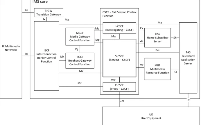
IMS core
CSCF - Call Session Control Function UE User Equipment S-CSCF (Serving – CSCF) I-CSCF (Interrogating – CSCF) P-CSCF (Proxy – CSCF) Mw Mw Home Subscriber HSS Server Cx Cx TAS Telephony Application Server MRF Multimedia Resource Function Mr Cr BGCF Breakout Gateway Control Function MGCF Media Gateway Control Function IBCF Interconnection Border Control Function Mx Mx Mx Mg Mg Mj Mx Ut TrGW Transition Gateway Ix Gm ISC Ma Sh IP Multimedia Networks Ici Izi
21
The Mx interface is between a x-CSCF and another x-CSCF within the IMS core network (e.g. P-CSCF to I/S-CSCF). The protocols used on the Mw interface are SIP and SDP.
Mg Interface (xCSCF – MGCF)
The Mg reference point allows the MGCF to forward incoming SIP/SDP messages that the MGCF has interworked from the CS Network to the CSCF. The protocols used on the Mg interface are SIP and SDP.
Mi Interface (xCSCF – BGCF)
The Mi reference point allows the Serving CSCF to forward the SIP/SDP messages to the Breakout Gateway Control Function for the purpose of MGCF selection for interworking with CS networks. The protocols used on the Mi interface are SIP and SDP.
Mj Interface (BGCF – MGCF)
The Mj reference point allows the Breakout Gateway Control Function to exchange SIP/SDP messages with the BGCF for the purpose of interworking with CS networks. The protocols used on the Mj interface are SIP and SDP.
ISC Interface (S-CSCF –TAS)
The ISC interface is between S-CSCF and Telephony Application Server and is used to interact with the MMTel supplementary services implemented on the TAS. The protocol used on the ISC interface is SIP.
Mr Interface (S-CSCF – MRF)
The Mr interface is between the S-CSCF and the MRF to allow interaction with the media resource for specific supplementary services (e.g. conference call). The protocol used on the Mr interface is SIP/SDP.
Mr’ Interface (TAS – MRF)
The Mr' interface is between the Telephony Application Server and the MRF to allow interaction with the media resource for specific supplementary services (e.g. conference call). The protocol used on the Mr' interface is SIP/SDP.
Cr Interface (TAS – MRF)
The Cr interface is between the Telephony Application Servers and the MRF. And is used for sending/receiving XML encoded media service requires (Cr) which are served by the MRF.
Mb Interface (media bearer)
Mb interface is the media bearer plane between UEs and network elements that interact with the bearer (e.g. MRF). The protocol is based on symmetric RTP/RTCP over UDP.
Ici Interface (IBCF – IBCF)
Ici interface is between an IBCF and another IBCF or I-CSCF belonging to a different IMS network. The protocols used on the Ici interface are SIP and SDP.
22
Izi Interface (TrGW – TrGW)
The Izi interface is between a TrGW and another TrGW or media handling node belonging to a different IMS network. The protocols used on the Izi interface are RTP and MSRP.
3.4.3
IMS protocols
For UE and IMS subsystem connectivity, in particular of voice services, important the following protocols:
Session Initial Protocol (SIP)
Session Description Protocol (SDP)
Real-time Transport Protocol (RTP)
RTP Control Protocol (RTCP)
IP Security (IPsec)
Session Initial Protocol (SIP)
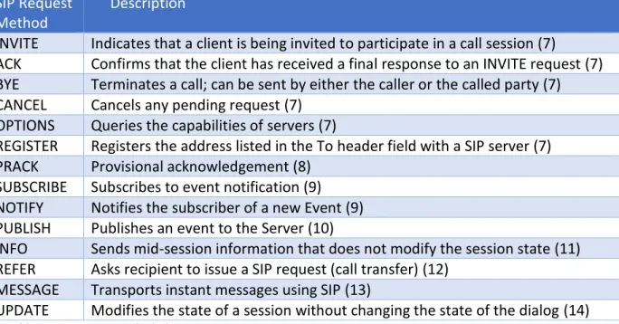
Session Initial Protocol is used to create, modify and terminate multimedia sessions. It is client-server signaling protocol, for delivering media tasks is used RTP/RTCP. SIP is a sequential request-response protocol. Every SIP request begins with a starting line that includes the name of the method (request type). A Request-Line contains a method name, a Request-URI, and the protocol version separated by a single space (SP) character. The Request-Line ends with CRLF.
Request-Line example: Method SP Request-URI SP SIP-Version CRLF
SIP Request Method
Description
INVITE Indicates that a client is being invited to participate in a call session (7)
ACK Confirms that the client has received a final response to an INVITE request (7) BYE Terminates a call; can be sent by either the caller or the called party (7) CANCEL Cancels any pending request (7)
OPTIONS Queries the capabilities of servers (7)
REGISTER Registers the address listed in the To header field with a SIP server (7)
PRACK Provisional acknowledgement (8)
SUBSCRIBE Subscribes to event notification (9) NOTIFY Notifies the subscriber of a new Event (9) PUBLISH Publishes an event to the Server (10)
INFO Sends mid-session information that does not modify the session state (11) REFER Asks recipient to issue a SIP request (call transfer) (12)
MESSAGE Transports instant messages using SIP (13)
UPDATE Modifies the state of a session without changing the state of the dialog (14) Table 3.1 SIP Request Methods description
SIP responses are distinguished from requests by having a Status-Line as their start-line. A Status-Line consists of the protocol version followed by a numeric Status-Code and its
associated textual phrase, with each element separated by a single SP character. Status-Line example: SIP-Version SP Status-Code SP Reason-Phrase CRLF
23
Request start line INVITE sip:[email protected] SIP/2.0
Request header Via: SIP/2.0/UJP
10.10.1.99:5060;branch=z9hG4bK343b:628;rport From: “Test 15” <sip:[email protected]>tag=as58f4201b To: <sip:[email protected]> Contact : <sip:[email protected]> Call-ID: 326371826c80e17e6c:[email protected] CSeq: 102 INVITE User-Agent : Asterisk PBX Max-Forwards : 70
Date: Wed, 06 Dec 2009 14 :12 :45 GY.T
Allow: INVITE, ACK, CANCEL, OPTIONS, BYE, REFER, SUBSCRIBE, NOTIFY Supported: replaces Content-Type : application/adp Content-Length: 258 <blank line> Message body (SDP message) v=0
o=Joe Spirent 1821 1821 IN IP4 10.10.1.99 s=Spirent Seminar : IMS & VoLTE
c=IN IP4 10.10.1.99 t=0 0 m=audio 11424 RTP/AVP 0 8 101 a=rtpmap:0 PCMU/8000 a=rtpmap:8 PCMA/8000 a=rtpmap:101 telephone-event/8000 a=fmtp:101 0-16 a=silenceSupp:off - - - - a=ptime:20 a=sendrecv
Table 3.2 Sample SIP request with SDP in message body from SPIRNET seminar (15)
Session Description Protocol (SDP)
Session Description Protocol (SDP) – is used to describe multimedia sessions. SDP is
contained in the body part of SIP. An SDP message is composed of a fields , whose names are abbreviated by a single lower-case letter. It conveys the name and purpose of the session, the media, protocols, codec formats, timing and transport information.
For example in Table 3.2 Sample SIP request with SDP in message body from SPIRNET seminar the SDP message body describes the owner (“Joe Spirent”), the session (“Spirent Seminar: IMS &VoLTE”), some connection information (IP4 10.10.1.99), the media (audio) and some suggested attributes of the media (PCMU, PCMA, etc.). (15)
Real-time Transport Protocol (RTP) and RTP Control Protocol
IMS subsystem uses RTP as the media data transfer protocol. RTP provides end-to-end delivery services for data with real-time characteristics, such as interactive audio and video. RTCP in IMS is used to provide Quality of Service (QoS) information and for synchronizing RTP streams. RTP and RTCP are always paired in port assignments. One port is used for audio data, and the other is used for control (RTCP) packets. For example: if RTP port equals “n”, then RTCP port will be equal “n+1”.
24
The audio conferencing application used by each conference participant sends audio data in small chunks of, say, 20 ms duration. Each chunk of audio data is preceded by an RTP header; RTP header and data are in turn contained in a UDP packet. The RTP header indicates what type of audio encoding (such as PCM, ADPCM or LPC) is contained in each packet so that senders can change the encoding during a conference, for example, to accommodate a new participant that is connected through a low-bandwidth link or react to indications of network congestion. (16)
The Internet, like other packet networks, occasionally loses and reorders packets and delays them by variable amounts of time. To cope with these impairments, the RTP header contains timing information and a sequence number that allow the receivers to reconstruct the timing produced by the source, so that in this example, chunks of audio are contiguously played out the speaker every 20 ms. This timing reconstruction is performed separately for each source of RTP packets in the conference. The sequence number can also be used by the receiver to estimate how many packets are being lost. (16)
Since members of the working group join and leave during the conference, it is useful to know who is participating at any moment and how well they are receiving the audio data. For that purpose, each instance of the audio application in the conference periodically multicasts a reception report plus the name of its user on the RTCP (control) port. The reception report indicates how well the current speaker is being received and may be used to control adaptive encodings. In addition to the user name, other identifying information may also be included subject to control bandwidth limits. A site sends the RTCP BYE packet when it leaves the conference. (16)
25
VoLTE service requirements
4.1
Adaptive Multi-Rate (AMR) Speech Codec
The AMR codec is originally developed and standardized by the European
Telecommunications Standards Institute (ETSI) for GSM cellular systems. It is now chosen by the Third Generation Partnership Project (3GPP) as the mandatory codec for 3G and 4G cellular systems.
The AMR codec is a multi-mode codec that supports eight narrow band speech encoding modes with bit rates between 4.75 and 12.2 kbps. The sampling frequency used in AMR is 8000 Hz and the speech encoding is performed on 20 ms speech frames. Therefore, each encoded AMR speech frame represents 160 samples of the original speech.
Similar to AMR, the AMR-WB codec is also a multi-mode speech codec. AMR-WB supports nine wide band speech coding modes with respective bit rates ranging from 6.6 to 23.85 kbps. The sampling frequency used in AMR-WB is 16000 Hz and the speech processing is performed on 20 ms frames. This means that each AMR-WB encoded frame represents 320 speech samples. Both codecs support voice activity detection (VAD) and generation of comfort noise (CN) parameters during silence periods.
The main requirements of AMR
UE has to support all modes
If wideband AMR is available, it has to be supported too
Both (UE and network) must support wideband modes 12.65, 8.85 and 6.6 kbps
AMR coder takes 20 ms samples of speech and encodes them into frames
Frames must be transferring across the network - RTP
Delay between speech generation and reception should be below 150 ms else human can notice quality degradation
License for using AMR
4.2
Robust Header Compression
UE and network must support Robust Header Compression (RoHC). The UE and network must be able to apply the compression to packets that were carry over the radio bearer dedicated for the voice media. At minimum, UE and network must support "RTP/UDP/IP" to compress RTP packets and "UDP/IP" to compress RTCP packets. The UE and network must support these profiles for both IPv4 and IPv6. (17)
4.3
LTE Radio Capabilities
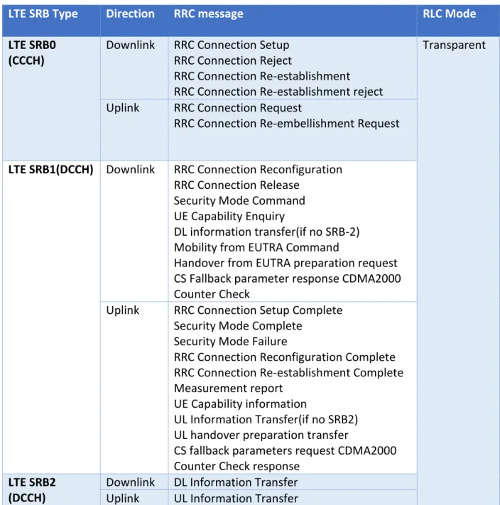
LTE Signaling radio bearers (SRB) are used for the transfer of RRC and NAS signaling messages.
1. RRC messages are used as signaling between UE and eNodeB.
2. NAS (Non Access Stratum) messages are used as signaling between UE and MME. (18)
26
RRC messages can be used to encapsulate NAS messages for their transfer between UE and eNodeB. The S1 application protocol is later used to transfer NAS messages between eNodeB and MME. The UE must support the following combination of radio bearers for Voice over IMS:
SRB1 + SRB2 + 4 x AM DRB + 1 x UM DRB
The network must support the following combination of radio bearers: SRB1 + SRB2 + 2 x AM DRB + 1 x UM DRB
One AM Data Radio Bearer (DRB) is utilized for Evolved Packet System (EPS) bearer with Quality of Service Class Indicator (QCI) = 5 and another AM DRB for EPS bearer with QCI = 8/9. UM DRB is utilized for EPS bearer with QCI = 1. (17)
LTE SRB Type Direction RRC message RLC Mode
LTE SRB0 (CCCH)
Downlink RRC Connection Setup RRC Connection Reject
RRC Connection Re-establishment RRC Connection Re-establishment reject
Transparent
Uplink RRC Connection Request
RRC Connection Re-embellishment Request
LTE SRB1(DCCH) Downlink RRC Connection Reconfiguration RRC Connection Release
Security Mode Command UE Capability Enquiry
DL information transfer(if no SRB-2) Mobility from EUTRA Command
Handover from EUTRA preparation request CS Fallback parameter response CDMA2000 Counter Check
Uplink RRC Connection Setup Complete
Security Mode Complete Security Mode Failure
RRC Connection Reconfiguration Complete RRC Connection Re-establishment Complete Measurement report
UE Capability information
UL Information Transfer(if no SRB2) UL handover preparation transfer
CS fallback parameters request CDMA2000 Counter Check response
LTE SRB2 (DCCH)
Downlink DL Information Transfer Uplink UL Information Transfer Table 4.1 LTE Signaling Radio Bearer types (18)
27
4.4
RLC configurations
Radio Link Control (RLC) entity must be configured to perform data transfer in the following modes;
Unacknowledged Mode (UM) for EPS bearers with QCI = 1
Acknowledged Mode (AM) for EPS bearers with QCI = 5
Acknowledged Mode (AM) for EPS bearers with QCI = 8/9
Voice service can tolerate error rates on the order of 1%, while benefiting from reduced delays, and is mapped to a radio bearer running the RLC protocol in unacknowledged mode (UM).
4.5
Guaranteed bit rate (GBR) bearer
Voice is one of the LTE services that require a guaranteed bit rate (GBR) bearer, although it is a very low data rate compared to LTE peak rates. The GBR bearer for voice requests dedicated network resources related to the Guaranteed Bit Rate (GBR) for AMR codec values. The network resources associated with the EPS bearer supporting GBR must be permanently allocated by admission control function in the eNodeB at bearer establishment. Reports from UE, including buffer status and measurements of UE’s radio environment, must be required to enable the scheduling of the GBR. In UL it is the UE’s responsibility to comply with GBR
requirements. (17)
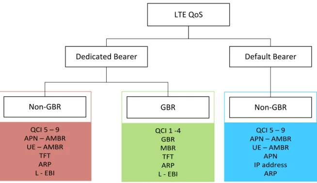
Dedicated bearer can be subdivided into Non-GBR and GBR types. GBR provides guaranteed bit rate and is associated with parameters like GBR and MBR
QCI 5 – 9 APN – AMBR UE – AMBR TFT ARP L - EBI QCI 1 -4 GBR MBR TFT ARP L - EBI QCI 5 – 9 APN – AMBR UE – AMBR APN IP address ARP LTE QoS
Dedicated Bearer Default Bearer
Non-GBR GBR Non-GBR
28
1. GBR: The minimum guaranteed bit rate per EPS bearer. Specified independently for uplink and downlink
2. MBR: The maximum guaranteed bit rate per EPS bearer. Specified independently for uplink and downlink
On the other hand, Non-GBR bearer does not provide guaranteed bit rate and has parameter like A- AMBR and UE- AMBR. (19)
1. A-AMBR: APN Aggregate maximum bit rate is the maximum allowed total non-GBR throughput to specific APN. It is specified interdependently for uplink an downlink 2. UE -AMBR: UE Aggregate maximum bit rate is the maximum allowed total non-GBR
throughput among all APN to a specific UE
For an IMS session request for a Conversational Voice call (originating and terminating), a dedicated bearer for IMS-based voice must be created utilizing interaction with dynamic PCC. The network must initiate the creation of a dedicated bearer to transport the voice media. The dedicated bearer for Conversational Voice must utilize the standardized QCI value of one (1) and have the associated characteristics. (17)
The network must not create more than one dedicated bearer for voice media. Therefore, the UE and network must be able to multiplex the media streams from multiple concurrent voice sessions. (17)
For IMS session termination of a Conversational Voice call, the dedicated bearer must be deleted utilizing interaction with dynamic PCC. The network must initiate the deletion of the bearer.
4.6
P-CSCF Discovery
The UE and packet core must support the procedures for P-CSCF discovery via EPS. The UE shall indicate P-CSCF IPv6 Address Request and P-CSCF IPv4 Address Request when performing the following procedures:
1. During the initial attach when establishing PDN connection to the default APN, 2. During the initial attach when establishing PDN connection to the IMS well-known
APN, and
3. During the establishment of the PDN connection to the IMS well-known APN when already attached,
4. During the attach procedure for emergency bearer services, and
5. During the establishment of the PDN connection for emergency bearer services when already attached.
The UE must use the P-CSCF addresses received during PDN connection establishment to the IMS well-known APN when accessing non-emergency services, and must use the P-CSCF
addresses received during PDN connection establishment for emergency bearer services when accessing emergency services. (17)
29
4.7
Addressing
The UE and IMS core network must support Public User Identities, which includes all of the following types of addresses:
Alphanumeric SIP-URIs. Example: sip:[email protected]
MSISDN represented as a SIP URI. Example: sip:[email protected];user=phone MSISDN represented as a Tel URI. Example: tel:+447700900123
4.8
Handovers
Handover are still needed for mobility
eNB knows the QCI but not the service
It can change process based on QCI
Signaling is used to announce any changes
“Data forwarding ” feature – forwards data from old eNB to the new eNB while handover is in progress
30
The basic call flows scenarios
The basic call flows that cover the following scenarios: (2) 1. Attachment and IMS Registration
2. Detachment and IMS de-registration 3. IMS voice call establishment and teardown
4. IMS multimedia (voice/video) call establishment and teardown 5. Adding video to an established voice call
6. Removing video from an established multi-media call
During my work in VoLTE implementation, I target on three main situations: VoLTE UE Attachment and IMS Registration, VoLTE UE to VoLTE UE Voice Call Establishment and Clearing.
5.1
Attachment and IMS Registration
5.1.1
Default Bearer establishment for attach to IMS
RRC CONNECTION REQUEST message is used to request the E-UTRAN for the establishment of an RRC connection. It is sent as part of the Random Access procedure. It is transferred using SRB0 on the Common Control Channel (CCCH) because neither SRB1 nor a Dedicated Control Channel (DCCH) has been setup at this point.
As the next step, the VoLTE UE initiates the Attach Request to the eNodeB. With mandatory information including:
EPS Attach Type
NAS key set identifier
IMSI
UE network capability
DRX parameters
PDN Type (set to IPv4v6)
PCO (P-CSCF IPv4 Address Request, P-CSCF IPv6 Address Request, IPv4 Link MTU Request)
Voice Domain Preference and UE’s Usage Setting (indicating support of IMS voice)
ESM message container
The eNodeB selects the MME from the RRC parameters and forwards the Attach Request to the MME with the Selected Network and the TAI+ECGI location information of the cell where it received the message.
Authentication and security mechanisms are performed to activate integrity protection and NAS ciphering. The MME shall initiate the Security Mode Command to the UE that containing:
The Selected NAS algorithms
EKSI
31
UE Security Capability
The UE responds with the Security Mode Complete with the NAS-MAC and ME Identity. After the completion, all NAS messages are protected by the NAS security functions (integrity and ciphering).
The MME performs an Update Location to the HSS to retrieve the subscriber profile. Additional information:
International Mobile Subscriber Identity (IMSI)
MME Identity
ME Identity
MME capabilities
Homogenous support for IMS Voice over PS session
The HSS confirms the Update Location to the MME with the related IMSI and subscriber data containing a PDN subscription context with a subscribed QoS profile and subscribed APN-AMBR (Aggregate Maximum Bit Rate).
The MME initiates a Create Session Bearer request to the SGW to create a default bearer for VoLTE IMS signaling. This message contains:
IMSI
32
MSISDNIMS-APN
QCI=5
ARP value
APN-AMBR
user location information (TAI+ECGI)
UE Time Zone
RAT-type (EUTRAN)
PCO
The SGW creates a new entry in the EPS Bearer table, allocating a relevant TEID for the control plane and the user plane, which enables it to route GTP control plane traffic between the MME and the PGW, and forwards the request to the PGW.
The PGW allocates an IP Address (which can be IPv4 or IPv6) for the UE and utilizes dynamic PCC to initiate a Credit Control Request to the PCRF to obtain the default PCC rules for the default bearer to be used for IMS signaling. Message also include:
IMSI
UE IP Address
default bearer QoS parameters (i.e. QCI=5, ARP, APN-AMBR)
user location information
time zone information
RAT type (EUTRAN)
The PCRF binds the related policy rules to the IP Address of the default bearer, and responds to the PGW with the default TFT (traffic flow template) and potentially modified QoS
parameters. The PGW creates a new entry in the EPS Bearer table, allocating relevant TEID for the control plane and the user plane, which enables it to route user plane data between the SGW and the IMS network with the related policy rules obtained from the PCRF applied.
The PGW sends a Create Session Response to the SGW with the follow parameters:
IP Address for the UE
QoS parameters
PCO
Relevant TEID's for the GTP control plane and GTP user plane
The PGW maps the IMS-APN received in the request to a pre-configured IMS P-CSCF IP address and inserts this into the PCO.
The SGW returns the Create Session Response to the MME. The MME sends an Attach Accept to the eNodeB with:
IMS-APN
IP Address for the UE
QoS parameters
PCO
IMS Voice over PS supported indication
33
ESM message container
The eNodeB communicates with the UE to update the RRC configuration and includes the information received from the core network as part of the create session request.
The UE sends the Attach Complete message to the eNodeB, which forwards to the MME. At this time, the UE is capable of sending uplink packets.
The MME initiates a Modify Bearer Request to the SGW including:
EPS Bearer Identity
eNodeB address
and eNodeB TEID
The SGW acknowledges the request to the MME and is capable of sending downlink packets. At this stage, the VoLTE UE is attached to the network via a default bearer that is established for IMS Signaling.
5.1.2
IMS registration
The VoLTE UE initiates a SIP REGISTER to the P-CSCF, using the P-CSCF IP Address that was made available during the LTE Attach. The registration request contains:
Within the Contact header, the IMS Communication Service Identifier's (ICSI) for IMS Multimedia Telephony:
o service.ims.icsi.mmtel, or urn:urn-7:3gpp-service.ims.icsi.mmtel;video
o sip.instance” containing an IMEI URN
The feature tag for SMS over IP:- +g.3gpp.smsip
The IMS Public User Identity (as derived above) in one of the forms below:- o Alphanumeric SIP-URI: e.g. [email protected]
o MSISDN as a SIP-URI: e.g. sip:[email protected];user=phone o MSISDN as Tel-URI: e.g. tel:+447700900123
The IMS Private User Identity as an NAI: e.g. username@realm
P-Access-Network-Info with:-
o access-type= 3GPP-E-UTRAN-FDD or 3GPP-E-UTRAN-TDD o UTRAN-cell-id-3gpp parameter
Request-URI set to the SIP-URI of the domain name of the home network
Related headers for IMS AKA parameters
The P-CSCF receives the SIP REGISTER request from the UE and inserts:
Path header with a SIP-URI identifying the P-CSCF for routing
P-Charging-Vector header with the icid-value
P-Visited-Network-ID to identify the P-CSCF's network domain Then P-CSCF forwards the request to the I-CSCF.
34
The I-CSCF queries the HSS using the User Authorization Request (UAR) for authorization and obtaining the S-CSCF name for the Public User Identity.
The HSS validates that the Public User Identity and Private User Identity are valid and not barred (UAA).
Once the S-CSCF is identified, the I-CSCF forwards the SIP REGISTER request to the S-CSCF.
The S-CSCF initiates a Multimedia Authentication Request to the HSS to retrieve the authentication vectors to perform IMS-AKA security. The HSS stores the related S-CSCF name for the Public User Identity being registered and returns the authentication vectors to the S-CSCF.
Upon receipt of the IMS AKA authentication vectors, the S-CSCF stores the XRES and replies to the SIP REGISTER request with a 401 “Unauthorized” response indicating that AKAv1-MD5 is the security mechanism to be used. The RAND and AUTN parameters, Integrity Key and Cipher Key are also included.
35
The P-CSCF removes the Cipher Key and Integrity Key from the 401 “Unauthorized” response and binds these to the Private User Identity with a set of temporary security associations for the result of the challenge.
The P-CSCF then forwards the response to the UE.
The UE extracts the RAND and AUTN parameters, calculates the RES, and derives the Cipher Key and Integrity Key from the RAND. The UE creates a temporary set of security associations based on parameters received from the P-CSCF (IPSec), and sends a new REGISTER request to the P-CSCF with a populated Authorization header containing the RES indicating that the message is integrity protected.
The P-CSCF checks the temporary security associations, and verifies the security related
information received from the UE. This P-CSCF forwards the SIP REGISTER request to the I-CSCF with the RES included.
The I-CSCF uses the User Authorization Request message to retrieve the S-CSCF name stored within the HSS, and forwards the request to the relevant S-CSCF.
The S-CSCF checks whether the RES received in the SIP REGISTER and the XRES previously stored match. The S-CSCF then performs the Server Assignment Request procedure to the HSS to download the relevant user profile and register the VoLTE UE. The S-CSCF stores the route header of the P-CSCF and binds this to the contact address of the VoLTE UE, this is used for routing to the VoLTE UE in future messages. Parameters of the P-Charging-Vector header are stored, and the S-CSCF sends a 200 OK response to the I-CSCF, including the user's display name (retrieved from the user profile in the HSS) within the P-Associated-URI, which forwards the message to the P-CSCF.
On receipt of the 200 OK from the I-CSCF, the P-CSCF changes the temporary set of security associations to a newly established set of security associations. It protects the 200 OK with these associations and sends the 200 OK to the VoLTE UE. All future messages sent to the UE will be protected using the security associations.
Optionally, the P-CSCF sends an AAR message to the PCRF to perform application binding to the default bearer (i.e. the P-CSCF is requesting to be informed in the event of the default bearer being lost/disconnected in order to trigger an IMS de-registration). The PCRF performs the binding and responds with a AAA message to the P-CSCF. Note that if this message is not sent, then IMS relies on other mechanisms to detect loss of the underlying default bearer, i.e., loss of connectivity (e.g. timeouts on trying to signal to the UE for an incoming call or the UE registers in the IMS with a new IP address).
On receipt of the 200 OK, the UE changes the temporary security association to a newly established set of security associations that will be used for further messages to the P-CSCF. The VoLTE UE is now registered with the IMS network for VoLTE services, with SIP signalling being transported over the default EPC bearer.
The S-CSCF sends a third party SIP REGISTER to the VoLTE AS, as configured in the initial filter criteria (iFC) within the subscriber profile. The TAS may use the User Data Request procedure to read VoLTE data stored in the HSS.
36
The VoLTE UE, P-CSCF and TAS shall subscriber to the registration event package using the SIP SUBSCRIBE message, in order to be notified on any change of registration state for the public user identity. In turn, the S-CSCF shall send a SIP NOTIFY to the subscribing entities informing them of the active registration status.
5.2
Basic VoLTE UE to VoLTE UE Voice Call Establishment
5.2.1
Originating Side
A VoLTE UE, shall perform call establishment by using the IMS network. The IMS Signalling shall be sent over the default bearer, and a new dedicated bearer shall be dynamically established for the voice traffic.
When a VoLTE UE originates a voice call from LTE, it executes the normal mobile origination procedure.
The VoLTE UE initiates a SIP INVITE request, containing the SDP offer with IMS media capabilities. The SDP offer shall contain the AMR Narrowband codec, and it is recommended that the AMR Wideband codec is included to provide support for HD Voice and shall indicate that local preconditions for QoS are desired but not yet met, using the segmented status type. That the media stream is set to inactive.The desired QOS for the remote end are set to “none” as the originating UE is unaware of the QOS requirements at the terminating side. The request is sent to the P-CSCF that was discovered during the registration procedure. The INVITE request contains:
1) Within the Contact header and the P-Preferred-Service header, the IMS Communication Service Identifier's (ICSI) for IMS Multimedia Telephony:
urn:urn-7:3gpp-service.ims.icsi.mmtel
2) The IMS Public User Identity of the calling-party in one of the forms below:
Alphanumeric SIP-URI: e.g. [email protected]
MSISDN as a SIP-URI: e.g. sip:[email protected];user=phone
MSISDN as Tel-URI: e.g. tel:+447700900123 3) P-Access-Network-Info with:
Access-type= 3GPP-E-UTRAN-FDD or 3GPP-E-UTRAN-TDD
UTRAN-cell-id-3gpp parameter
4) Request-URI set to the SIP-URI or tel-URI of the called-party.
The P-CSCF adds the P-Charging-Vector header and forwards the SIP INVITE to the S-CSCF that was identified during the registration process.
If an IMS-ALG/AGW is deployed, then the P-CSCF will also invoke the IMS-AGW over the Iq reference point to provide appropriate resources in the media plane.
The P-CSCF forwards the SIP INVITE to the S-CSCF The offered SDP address shall reflect the media pin-hole created in the IMS-AGW if applicable.
The S-CSCF receives the SIP INVITE from the P-CSCF, and invokes any VoLTE services as triggered by the initial filter criteria within the subscriber profile that was received during the IMS Registration.
37
The S-CSCF checks the P-Preferred-Service header in the SIP INVITE (e.g. MMTel ICSI) and verifies that the user is authorized for the service by validating against the subscribed services that were retrieved in the service profile during IMS Registration (Core Network Service Authorization – Service ID).
If the MMTel ICSI is not in the subscribed services, the INVITE request shall be rejected (403 Forbidden). If validated, the S-CSCF then adds the ICSI into the P-Asserted-Service header, and removes the P-Preferred-Service header.
Due to service logic within the user profile, and the identification of the call as a VoLTE call (i.e. MMTel ICSI), the S-CSCF shall route the SIP INVITE to the TAS at this point to invoke VoLTE
38
supplementary services. The TAS invokes any supplementary service logic and routes the SIP INVITE to the S-CSCF.
The S-CSCF determines that the Called-Party is within the home network (i.e. ENUM/DNS lookup/internal configuration) and routes the SIP INVITE to the I-CSCF to determine the terminating S-CSCF of the Called-Party.
The called party's VoLTE UE will return an SDP answer in a SIP 183 Progress message. The SDP answer should contain only one codec and indicates that preconditions are also desired but not yet met at the terminating end and that a confirmation should be sent when QOS
preconditions have been met at the originating side and that the media stream is inactive. This message is received by the S-CSCF and forwarded to the P-CSCF.
The P-CSCF uses the SDP answer to configure the IMS-AGW if deployed. In addition, the P-CSCF analyses the SDP in the SDP Answer and sends the
Authorize/Authenticate-Request message to the PCRF with the related service information (IP address, port numbers, information on media-type).
The PCRF authorizes the request and associates the service information with the stored subscription related information containing the information about the allowed service(s), QoS information and PCC Rules information. The PCRF identifies the affected IP-CAN session (e.g. default bearer) that has been established during the LTE Attach procedure, and initiates a Re-Authentication Request to the PGW to initiate the creation of a dedicated bearer for voice with the related QoS parameters (QCI=1, ARP) and the related traffic flow template. The PCRF must also subscribe to modifications related to the dedicated bearer in the PGW (e.g.
INDICATION_OF_RELEASE_OF_BEARER).
The PGW acknowledges the Re- Authentication Request to the PCRF, which then acknowledges the Authorize/Authenticate-Request message sent from the P-CSCF. At this point, the IMS SIP session and the dedicated bearer used for voice are bounded together via PCC.
The PGW sends the Create Bearer Request to the SGW to create the dedicated bearer for VoLTE media. This message contains the dedicated bearer identity, Linked Bearer Identity to identify the associated default bearer, the traffic flow template, and the associated QoS parameters (QCI=1, ARP, GBR and MBR). The SGW sends the request to the MME.
The MME sends a Bearer Setup Request message to the eNodeB with the dedicated bearer identity, Linked Bearer Identity, the traffic flow template, and the associated QoS parameters in order to activate the dedicated bearer for voice traffic.
The eNodeB maps the QoS parameters to those required for the radio bearer, and then signals a RRC Connection Reconfiguration to the UE.
The UE stores the dedicated bearer identity and links the dedicated bearer to the default bearer indicated by the Linked EPS Bearer Identity. The UE binds the TFT and associated QoS parameters to the dedicated bearer, and acknowledges the request to the eNodeB, which then acknowledges the Bearer Request Setup to the MME.
39
The MME sends the Create Bearer Response message to the SGW to acknowledge the bearer activation. The message includes the dedicated bearer identity and User Location Information (ECGI) and forward to the PGW.
The P-CSCF forwards the SIP 183 Progress response to the VoLTE UE. This message shall also utilize 100rel and the originating UE shall generate a PRACK which is transited to the
terminating side of the call with an associated 200 OK (PRACK) being received.
The VoLTE UE shall reserve internal resources to reflect the SDP answer and shall confirm resource reservation by sending a SIP UPDATE message with a new SDP Offer confirming the selected codec, that local preconditions have been met at the originating end (due to the establishment of the dedicated bearer) and that the media stream is now set to active.
The UPDATE message is forwarded via the P-CSCF and S-CSCF to the terminating leg of the call. Note that if the SDP Answer in the 183 Progress message contained more than one voice codec, then the UE would ensure only a single codec from that multiple list was included in the new Offer in the UPDATE message.
The 200 OK (UPDATE) response is received from the terminating leg of the call containing the SDP answer containing a single voice codec and confirming that preconditions are also met at the terminating side and that the media stream is active. This message is passed onto the originating UE via the S-CSCF and P-CSCF.
As preconditions have been met, the terminating UE is now alerted and shall send a SIP 180 (Ringing) response that is received by the S-CSCF and onto the P-CSCF and originating UE.
The P-Early-Media header is not present in the SIP 180 Ringing message and so the UE will generate local ring tone to the subscriber. This message shall not utilize 100rel as there is no SDP within the message.
When the called party's VoLTE UE has answered the call, it sends a 200 OK to the calling party VoLTE UE. This is received by the S-CSCF and forwarded to the P-CSCF. The P-CSCF invokes the PCRF with an AAA message to enable both the uplink and downlink of the dedicated bearer.
In turn the PCRF invokes the GW with a RAR message to enable the media flows at the P-GW.
The P-CSCF (IMS-ALG) invokes the IMS-AGW (if deployed) to ensure that duplex media can be conveyed via IMS-AGW at this point.
The P-CSCF forwards the SIP 200 OK (INVITE) to the VoLTE UE.
The VoLTE UE receives the 200 OK, and sends a SIP ACK message to acknowledge that the call has been established.
At this stage, the VoLTE UE has a call established with voice traffic sent over the dedicated bearer and via the IMS-AGW. The IMS signaling is sent over the default bearer. (2)
40
5.2.2
Terminating Side
A VoLTE UE shall receive a call via IMS network. The IMS signaling shall be sent over the default bearer, and the network establish a new dedicated bearer for the voice traffic.
The S-CSCF receives a SIP INVITE containing an SDP offer. The SDP offer shall contain the AMR Narrowband codec, and optionally the AMR Wideband codec. The SDP indicates that preconditions are applicable and that QOS preconditions are desired but not yet reserved at the originating side. The media stream is set to inactive.
41
The S-CSCF invokes any VoLTE services as triggered by the initial filter criteria within the subscriber profile that was received during the IMS Registration. The S-CSCF shall route the SIP INVITE to the TAS at this point to invoke VoLTE supplementary services. The TAS invokes any supplementary service logic and routes the SIP INVITE to the S-CSCF. The S-CSCF routes the SIP INVITE to the terminating P-CSCF that was associated to the subscriber during IMS registration.
If an IMS-ALG/AGW is deployed, then the P-CSCF (IMS-ALG) invokes the IMS-AGW to reserve resources for the media connection. In this event, the SDP address in the INVITE is over-written to reflect the media pin-hole created on the IMS-AGW.
The P-CSCF forwards the SIP INVITE to the VoLTE UE.
When the VoLTE UE receives the SIP INVITE it shall allocate resources for the call and select one voice codec from the SDP offer. The UE shall send a SIP 183 Progress response containing the SDP Answer. The message shall indicate that 100rel is required. The SDP Answer indicates that QOS preconditions are desired but not yet met at the terminating side of the call. In addition, the SDP shall indicate that the originating side should confirm when its local QOS preconditions have been met.
On receipt of the SIP 183 Progress message, the P-CSCF updates the IMS-AGW if applicable with the SDP answer from the UE and sends the Authorize/Authenticate-Request message to the PCRF with the related updated service information (IP address, port numbers, information on media-type).
The PCRF authorizes the request and associates the service information to the stored subscription related information containing the information about the allowed service(s), QoS information and PCC Rules information. The PCRF identifies the affected IP-CAN session that has been established during the LTE Attach procedure, and initiates a Re-authentication
request to the PGW to initiate the creation of a dedicated bearer for voice with the related QoS parameters (QCI=1, ARP) and the related traffic flow template. The PCRF shall also subscribe to modifications related to the dedicated bearer in the PGW (e.g. LOSS_OF_BEARER,
INDICATION_OF_RELEASE_OF_BEARER).
The PGW acknowledges the Re- Authentication Request to the PCRF, which then
acknowledges the Authorize/Authenticate-Request message sent from the P-CSCF. At this point the IMS SIP session and the dedicated bearer used for voice are bound together via PCC.
The PGW sends the Create Bearer Request to the SGW to create the dedicated bearer for VoLTE media. This message contains the dedicated bearer identity, Linked Bearer Identity to identify the associated default bearer, the traffic flow template, and the associated QoS parameters (QCI=1, ARP, GBR and MBR), etc. The SGW sends the request to the MME.
The MME sends a Bearer Setup Request message to the eNodeB with the dedicated bearer identity, Linked Bearer Identity, the traffic flow template, and the associated QoS parameters in order to activate the dedicated bearer for voice traffic.
The eNodeB maps the QoS parameters to those required for the radio bearer, and then signals a RRC Connection Reconfiguration to the UE. The UE stores the dedicated bearer
identity and links the dedicated bearer to the default bearer indicated by the Linked EPS Bearer Identity. The UE binds the TFT and associated QoS parameters to the dedicated bearer, and