A Survey on Resiliency Techniques in Cloud
Computing Infrastructures and Applications
Carlos Colman-Meixner, Chris Develder
∗, Massimo Tornatore
†, and Biswanath Mukherjee
University of California, Davis, USA,∗Ghent University – iMinds, Belgium,†Politecnico di Milano, Italy {cecolmanmeixner, mtornatore, bmukherjee}@ucdavis.edu,∗[email protected],†[email protected]Abstract—Today’s businesses increasingly rely on cloud com-puting, which brings both great opportunities and challenges. One of the critical challenges is resiliency: disruptions due to failures (either accidental or because of disasters or attacks) may entail significant revenue losses (e.g., US$ 25.5 billion in 2010 for North America). Such failures may originate at any of the major components in a cloud architecture (and propagate to others): (i) the servers hosting the application, (ii) the network interconnecting them (on different scales, inside a data center, up to wide-area connections), or (iii) the application itself. We comprehensively survey a large body of work focusing on resilience of cloud computing, in each (or a combination) of the server, network, and application components.
First, we present the cloud computing architecture and its key concepts. We highlight both the infrastructure (servers, network) and application components. A key concept is virtualization of infrastructure (i.e., partitioning into logically separate units), and thus we detail the components in both physical and virtual layers. Before moving to the detailed resilience aspects, we provide a qualitative overview of the types of failures that may occur (from the perspective of the layered cloud architecture), and their consequences.
The second major part of the paper introduces and categorizes a large number of techniques for cloud computing infrastructure resiliency. This ranges from designing and operating the facilities, servers, networks, to their integration and virtualization (e.g., also including resilience of the middleware infrastructure).
The third part focuses on resilience in application design and development. We study how applications are designed, installed, and replicated to survive multiple physical failure scenarios as well as disaster failures.
Index Terms—Cloud computing, resilience, virtualization, mid-dleware, optical networks, disaster resilience.
I. INTRODUCTION
In the 1960s, the visionary computer scientist John Mc-Carthy predicted the evolution towards service-oriented sys-tems, such as today’s cloud computing [1]. Thirty years later, the age of service-oriented computation (SOC) started with the advent of the Internet, that quickly became the worldwide network needed to enable novel cloud services (e.g., email and web services). Convergence of multiple driving forces (i.e., the new SOC paradigm, the rising software industry, high-performance distributed computing, virtualization, and a renewed business interest) paved the road towards the realization of cloud computing [2].
The first widely-available cloud computing service was im-plemented and commercialized by Amazon in 2006 (EC2/S3 [3]). The concept was standardized by the National Institute of Standards and Technology (NIST) in 2009 [4]. Since then,
the importance of cloud computing has risen steadily: Forbes magazine highlighted a market growth of 34% per year and a US$ 19 billion market for 2016 [5]. Yet, with that growth also came the challenges faced by the information technology (IT) industry and service providers to satisfy the increasing demand and diversity of cloud computing services. A major challenge that needs to be overcome to support that growth and thus the massive migration of business services to the cloud is resiliency.
Indeed, even a single physical or software element failure may cause major disruption and severe effects on business rev-enues [6]: e.g., losses from cloud application and infrastructure failures are estimated at US$ 273 million in 2007–2013, for 28 cloud service providers, given 1,600 hours of disruptions [7].
We define the term resiliency as the capacity of a system
or an infrastructure or a business to remain reliable, failure
tolerant,survivable (i.e., recoverable),dependable, andsecure
(i.e., incorruptible) in case of any malicious or accidental
malfunctions or failures that result in a temporal or permanent service disruption [8], [9], [10] (see Glossary in Section VIII). In this work, we comprehensively survey a large set of studies focusing on resiliency in cloud computing, classified into two major groups: (1) resiliency in infrastructure and (2) resiliency in applications.
Approaches for resiliency in cloud infrastructure are
de-signed for the physical and virtualization layers of cloud infrastructure providers. ‘Virtualization’ means the logical partitioning of physical resources, to increase their utilization by sharing them among multiple users. In a cloud context, ‘resources’ include processing capacity (located in data cen-ters) and communication network capacity (within the data center, or on a larger, wide-area scale, providing inter-data center connectivity). Earlier surveys on resiliency focused on just a segment of the present-day cloud infrastructure, e.g., specifically for communication networks [11], [12] or data centers [13], [14]. Our survey, on the other hand, provides a holistic view of all cloud computing components and also covers integrated cloud resiliency, focusing on combined com-munication and computation infrastructures.
The main aim of the proposed approaches forresiliency in
cloud applicationsis to reduce the failure’s negative impact at
the cloud application level, where the service provider interacts with end users. Approaches in this group are classified into: (i) resilient application development, (ii) resilient application collaboration, and (iii) resilient application management.
We will discuss the surveyed resilience studies by
consid-ering different aspects. The first aspect concerns thelayers of
the cloud system architecture, with three1 high-level layers
as proposed in [16]: (i) application, (ii) virtualization, and
(iii) physical layer. These layers also relate to the service
model where applications deliver services over the Internet, and infrastructure, i.e., systems are in data centers [17]. The
second aspect is thetype of cloud service disruption: the cause
and severity of the failure that is considered [6], [18]. The third
aspect relates to keyadditional functionalityprovided by cloud
computing with respect to traditional SOC (virtualization, multi-tenancy, geo-distribution and ubiquitous access, dynamic resource provisioning, self-adaptability, etc.) [2], [15]. Finally,
we consider the fundamental resiliency techniquesto counter
failures (e.g., forecasting, pre-provisioning of extra capacity for protection, and post-failure recovery).
Section II starts by clarifying the cloud architecture and
associated terminology. Section III gives a general overview of cloud service disruptions, and introduces the terminology used to describe their causes, severity, and financial consequences. In Section IV, we explain the main conceptual solutions to
those disruptions, to come to a classification of resiliency
strategies that we subsequently adopt to survey the studies
detailing the solutions. We partition the studies in two
top-level categories: Section V discusses the infrastructure
re-silience, while Section VI coversapplication-layer resiliency.
Section VII concludes the paper with a summary of the major approaches (and how they compare), an analysis of major trends, and open problems in cloud resiliency followed by a glossary of important terms in Section VIII and references.
II. CLOUDCOMPUTINGCONCEPTS ANDDEFINITIONS
Here, we first summarize the cloud service model (Sec-tion II-A) and func(Sec-tionality that cloud computing provides beyond traditional service oriented computing (Section II-B). Readers familiar with cloud computing can directly move to our model and terminology of the architectural layers in Section II-C.
A. Service model
The cloud computing service model is usually referred to by an acronym “XaaS” (X-as-a-service, where X can be any offered cloud service) [16], [17]. Among the numerous
Xs, three baseline services are defined by NIST: (1)
Soft-ware-as-a-Service (SaaS), that provides access to online soft-ware applications to one or more tenants and/or end users (e.g.,
Dropbox, Google Docs); (2) Platform-as-a-Service (PaaS),
where a platform such as an operating system or an application development framework is provided to users (e.g., Amazon Web Service (AWS), Salesforce.com, MS Windows Azure);
(3)Infrastructure-as-a-Service (IaaS), where, of a given cloud
network infrastructure, a fraction of the connectivity, process-ing, and storage capacities are provided to one or many tenants
1Note that some previous surveys have also suggested a four-layer model of
application, platform, infrastructure, and hardware [15]. However, we choose the three-layer model suggested in [16] for the sake of simplicity.
(e.g., the EC2 cloud of Amazon [3], [16], [19]). According to [15], a PaaS provider’s cloud is very likely to run on top of an IaaS provider’s cloud, and many PaaS and IaaS providers tend to be the same organization. For these reasons, in this
survey, we refer to a SaaS provider as “cloud application
service provider” and to PaaS and IaaS provider as “cloud
infrastructure service provider”, as suggested in [17]. B. Cloud functionalities beyond traditional SOC
Functionalities that cloud computing provide with respect to traditional service-oriented computing include the follow-ing [4]:
1. Virtualizationprovides physical resource partitioning with
adaptability and privacy. Virtualization is largely adopted to achieve resource sharing, with isolation, and enables Migra-tion (see Glossary in SecMigra-tion VIII). There are three levels of virtualization: (i) application, (ii) operating system, and (iii) hardware [20]. Virtualized applications imply separate user spaces with specific isolated application instances (i.e., sessions). Operating-system level virtualization creates inde-pendent and isolated operating systems with all functionalities and attributes (i.e., virtual machines, VM). Hardware virtual-ization is the slicing of hardware resources (e.g., virtual optical networks) [20] (see Glossary in Section VIII).
2. Multi-tenancy is the possibility for multiple service
providers to share the physical infrastructure of a single oper-ator and/or for one service provider to use physical infrastruc-ture of multiple operators [15]. Multi-tenancy can be adopted to increase resiliency (e.g., SecondSite [21]), assuming that failures affecting multiple providers are unlikely.
3. Dynamic resource provisioning allows resources to be
leased and released from a pool, whenever needed. Most approaches for resiliency in physical infrastructure exploit it (e.g., Self-Adaptive Cloud Collaboration (SACC) [22]).
4. Geo-distribution and ubiquitous accessallow services and
data to be accessed from anywhere. These characteristics are shared with SOC and are also largely employed in support of disaster resiliency, e.g., when moving content to avoid massive disruption due to an expected disaster (e.g., DeepSky [23]).
5. Self-adaptability (i.e., self-migration and
self-reorganization) consists in the leasing and releasing of resources on demand from cloud providers by using automated resource-management features to reorganize their cloud computing infrastructures and respond efficiently to rapid changes in service demand (e.g., flash-crowd effects). Some approaches exploit this functionality by offering automatic failure mitigation in cloud computing operations (e.g., NetPilot [24]).
C. Layered cloud architecture
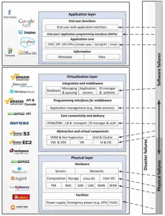
We now introduce the three-layer cloud architecture sug-gested in [16] and the taxonomy of components presented in [25]. Figure 1 illustrates the following layers, with sample organizations whose core businesses relate to the respective layer:
Fig. 1. Cloud computing and cloud service disruption.
1. Theapplication layeris the upper-most layer of the
hierar-chy where data and applications reside, and has four building blocks [25]:
1.a) End-user functions include end users’ and tenants’
interfaces and functionalities, e.g., web interfaces;
1.b) End-users’ application programming interface (EAPI)
defines an interface for development and customization of users’ or tenants’ applications;
1.c) Application core includes the engine of each cloud
application, e.g., Customer Relation Management (CRM), Enterprise Resource Planning (ERP); and
1.d) Information manages two different granularities of
information, dataandmetadata[25].
2. The virtualization layer supports the application demands
by organizing, managing, and providing access to resources of the physical layer, and comprises four building blocks [25]:
2.a) Integration and middleware components provide the
infrastructure with application development frameworks, mid-dleware capabilities, and useful functions such as database access, message interchanging, and queuing (e.g., a MapRe-duce interface). This building block also provides basic server functionalities for fundamental applications (e.g., email, web) and secure authentication functionalities (e.g., identity man-ager and authentication protocols) as a platform.
2.b) Programming interfaces for middleware comprise a
the infrastructure (e.g., the Restful Web Service API used by Amazon and GoGrid).
2.c) Core connectivity and deliverymanage the connectivity
to the infrastructure and define virtual topologies: Internet Protocol (IP) address management (IPAM) for internal and external IP addresses; Domain name system (DNS) for trans-lation of IaaS tenants’ IPs and domains (e.g., automatic AWS DNS name assignment); load balancers (LB) and transport which distribute workloads across servers, network links (e.g., AWS Auto-Scaling); identity access management (e.g., AWS credentials and X.509 certificates) functionality with network firewalls to control the access and provide security for the infrastructure and IaaS tenants’ data.
2.d) Abstraction and virtual components provide
abstrac-tion and virtualizaabstrac-tion of physical infrastructure for the ten-ants’ platforms and applications. This building block defines and controls the virtual machines (VMs) and virtual digital sites (VDS) by using hypervisors (virtual machine manager, VMM, and Xen), and maps virtual networks (VNets/VNs) integrated in cloud networks (CNs) over a substrate physical infrastructure (see Glossary in Section VIII).
3. The physical layer provides physical resources for
com-putation, communication, and storage data by defining two building blocks:
3.a) Hardware comprises the core data center equipment,
i.e., a pool of servers or physical machines (i.e., PM) con-nected using an intra-data center network composed of, e.g., switches and routers. Cloud infrastructure providers typically manage a network of data centers, connected by core networks (i.e., the inter-data center network).
3.b) Facilities refer to the supporting equipment
compris-ing power systems and HVAC (heatcompris-ing, ventilation, and air conditioning).
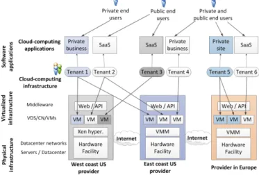
Figure 2 shows three cloud infrastructure providers manag-ing their virtualized infrastructure (i.e., servers, networks, data centers, networks of data centers, and facilities) by providing geographically-distributed and ubiquitous access to VMs for multi-tenant cloud applications. Some tenant’s applications are for private usage, while others provide services for end users (i.e., SaaS).
III. CLOUDSERVICEDISRUPTION
Before we detail the actual studies in subsequent sections, we first provide an overview of the causes of cloud service disruptions, the severity of the impacts, and their associated costs.
A. Causes of cloud service disruptions
Figure 1 illustrates what layers the various main causes have an effect on. The main causes can be characterized as follows:
1. Human errors: failures induced by human actions,
unin-tentionally or inunin-tentionally. When produced uninunin-tentionally, the error can be typically controlled and fixed (e.g., a cloud operator accidentally erases the profile of a user or shuts down some vital components). However, some errors can be
Fig. 2. Three cloud infrastructure providers in different geographical zones (i.e., US west coast, US east coast, and Europe); six tenants (i.e., SaaS application services and private business and sites); and two types of end users, using virtualization, multi-tenancy, and geo-distributed and ubiquitous access functionality of cloud computing.
intentionally produced by attacks or sabotage to destroy or disrupt cloud services and data [26].
2. Software failures:caused by software bugs, software aging,
errors in the application design, and malicious software (e.g., a
virus). Grottkeet al.[27] present a taxonomy of these failures.
3. Physical failures:physical component outages. These
fail-ures propagate vertically along the cloud system hierarchy (i.e., they start from the physical layer and propagate to the virtualization and application layers). Such failures can also propagate horizontally, affecting multiple hardware compo-nents (e.g., a failure of a server may produce post-failure traffic overload, subsequently failing more servers).
4. Disasters: natural disasters (tornadoes, earthquakes, etc.)
or human-induced ones (e.g., weapons of mass destruction, WMD). These failure scenarios often have a high impact, as they can propagate to the higher layers with a cascade of physical failures, software failures, and human errors. B. Impact of cloud service disruptions
We classify the service disruption severity in four levels of increasing impact [18]:
1. Masked disruption, when the service provider can recover
failed components without causing service disruption for end users and tenants.
2. Degraded service, when offered services get reduced in
quality, but are not interrupted. Some degradations may incur penalties (see next subsection).
3. Unreachable service, when the service or data still resides
in the servers, but cannot be accessed by end users or tenants. This is the most common case for network communication failures.
4. Corrupted service, when the service cannot be recovered
revenues and might initiate legal actions against the cloud service provider.
C. Consequences of cloud service disruptions
Cloud service providers, tenants, and users confront three different costs or losses induced by cloud service disruption:
1. Repair costs: paid by the cloud service provider when
failures affect cloud components. Vishwanath et al. [28]
provide a quantitative evaluation of the effect of failures in servers of large data centers. The study observed failures and replacement of servers of about 8% of 100,000 servers (i.e., 8,000 servers) in a period of 14 months, amounting to a total repair cost (without considering penalty) of around US$ 2.5 million. Similar results are reported in another study performed on the Google cloud infrastructure [18].
2. Penalty costs: incurred by cloud application and cloud
infrastructure providers when cloud services are disrupted by reducing their availability. As an example, the availability and penalty costs incurred by 28 cloud service providers due to service disruptions in 2007–2013 were estimated to amount to over US$ 273 million [7].
3. Business revenue losses:the missed business opportunities,
in an extended sense, due to cloud service outages. This can be very significant, given the dependency of today’s business on cloud computing services: [29] estimates a loss of US$ 25.5 billion for the year 2010, considering total or partial service disruptions in North American businesses.
IV. CLASSIFICATION OFRESILIENCY APPROACHES IN
CLOUDCOMPUTING
We now present the classification of resiliency in cloud computing, as adopted in the rest of the paper.
A. Resiliency strategies
Starting from the traditional classification of network resilience [11] and information technology resilience [9], we develop a comprehensive classification to cover all resiliency methods in cloud systems (i.e., methods applicable to cloud infrastructures as well as cloud applications). Our comprehen-sive classification comprises failure forecasting and removal, protection, and restoration:
1. Failure forecasting and removal:consists in using
measure-ments and/or estimations of possible failures and their conse-quences for the system to enhance system preparedness. For cloud infrastructure providers, failure forecasting and removal imply the reorganization of their infrastructure or software components to reduce or remove negative effects of failures before they occur. Degrading service can be considered as a removal approach because no additional capacity is pre-provisioned.
An example of failure forecasting and removal is resilient virtual machine migration using traffic demand estimation.
2. Protection: consists in pre-deploying redundant
computa-tional and communication capacity to recover the services in case a failure occurs. An example of these strategies applied
for cloud computing resiliency is the PipeCloud approach proposed in [30], which replicates entire tenant sites to provide protection.
Protection in distributed systems can be implemented through replication- and checkpoint-based methodologies [31]:
2.a) Replication is the most common protection method
and consists in the total or partial duplication of capacity (e.g., data, connections, machines, etc.) to provide protection in case of failure. The replication can be active or passive.
Active replication keeps many replicas updated (e.g., N
-version programming [32], RAID for disk storage, and 1:N
protection for communication networks [11]). The passive
scheme defines a working component and a dedicated backup replica where the backup is activated in the case of failure of the working component to avoid disruption (i.e., recovery
block [33], dedicated-path protection or 1:1 protection, and
shared-path protection [11]).
2.b) Checkpointingconsists in periodically saving the
sys-tem state in a different place, and restoring it from there if the original instance fails. An example of this method is the dynamic adaptive fault-tolerant strategy [31].
3. Restoration (a.k.a. recovery) refers to reactive and
best-effort schemes to reduce the impact of unexpected failures after they occur (as opposed to protection where redundant capacity is pre-deployed). A common recovery strategy for objects, applications, and components is the retry and reboot method, which consists in reloading the failed application or component [34]. A well-known strategy in networks is best-effort traffic re-routing and capacity re-provisioning to recover from physical network failures.
B. Metrics for resiliency objectives
The cloud computing resiliency approaches in this survey use very diverse metrics and objective functions to quantify and optimize their efficiency to reduce the severity or duration of cloud service disruption. To provide an overview, we classify metrics and objective functions based in three main areas:
1. Survivability is the capability of a system to survive a
certain kind of failures (i.e., single, multiple, and disasters) and attacks (i.e., WMD and Byzantine) [8] (e.g., recovery point objective (RPO) [35]).
2. Recovery time (RT)is the duration of the failure recovery
phase, typically used synonymously with mean time to repair (MTTR). The maximum tolerated RT is the recovery time objective (RTO), which is listed as part of the service-level objective (SLO) [35].
3. Cost in resources associated with the resiliency scheme
include CAPEX, OPEX, penalty, and revenue losses. C. Categorization of surveyed cloud resiliency approaches
Following the service model from Section II-A, we catego-rize the surveyed approaches in two main groups, discussed in detail in Sections V and VI, respectively:
1. Resiliency in cloud computing infrastructures contains
providers (i.e., IaaS and PaaS) that interact with the virtu-alization and/or physical layer, categorized in five types of infrastructure: facility, servers, networking, cloud integrated infrastructure, and cloud middleware.
2. Resiliency in cloud computing applications contains a
group of approaches designed for cloud application containing providers (i.e., SaaS), especially in interaction with cloud applications and contents.
V. RESILIENCYTECHNIQUES FOR CLOUDCOMPUTINGINFRASTRUCTURE
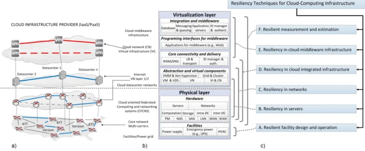
A cloud infrastructure provider designs, implements, and operates one or more data centers (i.e., data center facilities) interconnected by (inter- or intra-data center) communication facilities. We categorize the resiliency techniques for the cloud infrastructure in six groups (Fig. 3(c)).
The first two categories (A, B) deal with resiliency inside the data center (computing) infrastructure, and specifically
withresiliency of facilities(e.g., power, HVAC, etc.; see
Sec-tion V-A) andresiliency of servers(see Section V-B). The next
two categories (C, D) cover the resiliency in inter-data center communication networks (resiliency of networks, Section V-C) and resiliency of the integration of the communication network with the servers (resiliency in cloud integrated infrastructures, Section V-D). The final groups (E, F) focus on higher-level components (resiliency of middleware, Section V-E) and some measurement and estimation techniques for resiliency (resilient measurement and estimation, Section V-F).
A. Resilient facility design and operation
The primary concern for a cloud computing infrastructure provider is the resiliency of the data center facility to physical threats (i.e., disaster, sabotage, terrorist attacks, human errors, hardware trip, energy blackouts, WMD attacks) and logical threats (i.e., hackers and cyber terrorism). Figure 4 presents the elements of a data center facility. Resiliency targets for data center facilities are classified in tiers, ranging from tier 1 (looser requirements) to tier 4 (stricter requirements) [36]. To reach a higher tier, the cloud provider must provide resiliency at the level of the power systems, facility access, and facility operation, as discussed below.
1. Power resiliency: is the foundation of any cloud facility
given its critical dependency on energy supply.
1.a) Power redundancy: (or “emergency” power) protects
the facility against temporary power outage given the vulner-ability of the power grid to accidents, weather conditions, and malicious attacks [37], [38]. Two elements are recommended
to minimize the impact of power outages: uninterruptible
power supply (UPS) and emergency power generation (e.g.,
diesel engine) [18].
1.b) Resiliency against power quality issues:to protect the
facility due to sudden power fluctuations, spikes, or surges,
two elements are highly recommended: the secured power
distribution unit (PDU) and high-voltage DC distribution
(HVDC)[39], [40].
1.c) Resiliency against heat accumulation: redundant and
protected cooling systems to avoid devices from overheating (e.g., cooling systems) [18], [41].
2. Resilient facility access: techniques that protect cloud
infrastructure facilities from physical and cyber access of malicious users [25], [42].
3. Resilient facility operation:the implementation of training
and business continuity plans for prevention, detection, miti-gation, and recovery in case of disasters or attacks [25], [42]. Note that most resiliency techniques for facility design and operation are designed and tested by a multidisciplinary set of hardware and facility industries with the support and standardization of diverse organizations [9], [10], [25], [36], [42].
However, resiliency techniques for cloud infrastructure in-troduced in the following sections (V-B through V-F) were mostly proposed and tested by academia, typically with support from the information technology (IT) industry (i.e., hardware and software industries).
B. Resiliency in servers
Physical servers are essential for computation and storage in cloud computing infrastructures. Resiliency techniques in servers are implemented at both the physical and/or the virtualization layer (Fig. 5).
The surveyed approaches in server resiliency can be
di-vided in two groups:Resiliency in physical servers covering
resiliency techniques for physical servers and storage units;
Resiliency in virtual servers covering resiliency techniques
for virtual machines (VMs) and virtual storage (VS) (see Glossary in Section VIII). Figure 5 introduces the taxonomy for resiliency-in-servers techniques, while Table I summarizes and compares the approaches discussed in this subsection.
1. Resiliency in physical servers: covers a set of failure
removal, protection, and recovery methods acting at different levels, namely the physical machine (PM) components, the processes, and the data inside the physical server.
In this regard, the physical-failure isolation or fencing
method provides failure removal in PM components and
processes, while the process-level replication (PLR) method
enforces failure protection andprocess checkpointingprovides
failure recovery in process level [43], [44], [45]. Protection
and recovery of data are enforced by error detection and
correction coding (EDCC)andredundant array of independent
disks (RAID)techniques.
1.a) Failure isolation or fencing: is the isolation of failed
circuits or components in the hardware or process in the software to avoid failure propagation. An example of fencing
used in multiprocessor architecture is the failure contention
and component retirementin [46].
1.b) Process-level replication (PLR): consists in running
multiple executions of the process on different cores or CPUs (OS level) [44], and/or in different servers and/or in different cloud providers [45].
1.c) Process checkpointing: is the re-initialization of a
Fig. 3. A high-level view of the cloud computing infrastructure provider and taxonomy of resiliency techniques in cloud infrastructure: a) Example of a cloud computing infrastructure where integration between computing and communication resources is provided; b) The two layers of a cloud computing infrastructure with building blocks and their association with infrastructure layers in a); c) Taxonomy of resiliency techniques for cloud infrastructures and their association with layers in b).
Fig. 4. Cloud data center facility, racks, intra-data center network, power system, and cooling system.
Fig. 5. Taxonomy of resiliency techniques for servers.
or abnormal functions occur. Management tools for cloud infrastructures use reset/reboot to deal with failed process in PMs and VMs [47].
1.d) Error detection and correction coding (EDCC): is
a technique used in memories and large storage devices.
For memory (i.e., DRAM), one bit correction and two bits
detection[48] uses a periodic parity check to detect and correct
one bit per byte. For larger storage devices, there are two common coding techniques: the hamming code (HC) [49] and the Reed-Solomon (RS) code [50]. A major challenge for EDCC is the computing capacity required to process a large volume of data.
1.e) Redundant array of independent disks (RAID):
com-bines EDCC technique with data redundancy to enforce low-cost active and passive disk replication (i.e., mirroring). RAID stripes the data in bytes or blocks with single or double parity EDCC (i.e., single or multiple dedicated parity disk). The cloud infrastructure provider may install and configure its storage devices using one or a combination of six types of RAIDs. A summary and comparison of the various RAID types can be found in [51].
2. Resiliency in virtual server: includes resiliency methods
based on server virtualization acting on virtual machines (VM) or on virtualized storage (VS). Virtual server protection is
provided by VM replication in different servers, while VS
recovery is provided by VM migration and VS data coding.
By combining VS protection, recovery and failure removal,
some approaches use VM checkpointing and VM placement
techniques. VS resiliency techniques focus on data recovery and/or protection, but also include data integrity enforcement
byVS authenticationfor data integrity control, andVS resilient
T able I A P P R O A C H E S F O R R E S IL IE N C Y IN S E R V E R S T echniques and approaches Contrib ution for cloud infrastructure resilienc y / T ype and le v el of resilienc y enforced for serv ers T ype Approach/es Resilienc y technique Method Benefits Challenges PM VM Softw are ∗ Ph ysical † Attack Disaster †† Physical layer P/R PLR [43], [44], [45] Process replication PR F ast reco v ery Additional resources Single -+ + -R/R Fencing [46] F ailure isolation RM A v oid failure propag ation No reco v ery functions P artial -+ + -R UN Reset/reboot [47] Process checkpoint RE Lo w cost and R T Processing o v erhead Single -+ + + -R UN EDCC [48] Bit correction RE Data reco v ery Processing o v erhead P artial -+ + + -P/R RAID Data replication RE/PR Data reco v ery Processing o v erhead Single -++ ++ + -V irtualization layer P/R Zap [52] VM replication PR F ast VM reco v ery OS di v ersity and cost Single Single + + -P/R AutopoD [53] VM replication PR F ast VM reco v ery Lar ge VMs and cost Single Single ++ + -P/R FT -VM [54] VM replication PR F ast multi-VM reco v ery Lar ge VMs and cost Single Multiple ++ + -R UN Xen-VM-Mig [55] VM migration RE Lo w cost VM reco v ery Lar ge VM R T Single Single ++ + -R UN Vmotion [56] VM migration RE Lo w cost VM reco v ery Lar ge VM R T Single Single ++ + -R UN PostCL VM [57] VM migration RE Lo w VM R T and do wntime Lar ge service di v ersity Single Single ++ + -R UN P-FT [58] VM placement PR Lo w VM R T and do wntime T raf fic losses Single Single ++ + -R UN RD VM [59] VM placement PR Lo w VM R T and do wntime T raf fic losses Single Single ++ + -R UN SCVP [60] VM placement FR/RE Lo w VM R T and traf fic losses Lar ge service di v ersity Single Single ++ + + -R UN AFRC [61] VM placement PR Lo w VM R T and traf fic loses Lar ge service di v ersity Single Single ++ + + + P/R HA-VM-Place [62] VM placement RE/PR Multi-VMs with lo w R T Lar ge service di v ersity Multiple Multiple +++ ++ + -P/R HA-SBS-Place [63] VM placement RE/PR Multi-VMs with lo w R T Lar ge service di v ersity Multiple Multiple +++ ++ + + P/R HA-LOC [64] VM placement PR Multi-VMs with lo w R T Lar ge service di v ersity Multiple Multiple +++ ++ + -R UN ISR [65] VM checkpointing RE Lo w VM R T and cost Storage space usage Multiple Single +++ ++ + -R UN Remus [66] VM checkpointing RE Lo w VM R T and cost Checkpoint data update Multiple Single ++ ++ + -R UN KEMARI [67] VM checkpointing RE Lo w VM R T and cost Checkpoint data update Multiple Single ++ ++ + -R UN FVMCheck [68] VM checkpointing RE Lo w VM R T and cost Storage space usage Multiple Single +++ ++ + -R UN RemusDB [69] VM checkpointing RE Lo w VM R T and cost Lar ge service di v ersity Multiple Multiple +++ ++ + + R UN RS [50] VS coding RE Lo w data R T and cost Lar ge cost Single Single + + -R UN SRS [70] VS coding RE Lo w multi-data R T and cost Lar ge service di v ersity Single Single ++ + -R UN ByzantCode [71] VS coding RE/PR Byzantine attacks mitig ation Processing o v erhead Single Single ++ ++ ++ -R UN PoW erStore [72] VS authentication RE/PR Data consistenc y Byzantine attacks Single Single ++ + -PLA HAIL [73] VS design RE/PR Data reco v ery Lar ge cloud storage Multiple Multiple ++ ++ + -PLA Depot [74] VS design RE/PR Data reco v ery Lar ge clouds storage Multiple Multiple ++ ++ ++ -T ec hniques and appr oac hes T ype : type of utilization by the cloud pro vider . “PLA ” infrastructure planning (e.g., placement and dimensioning). “R UN” run-time. “P/R” the approach can be used in both phases. Method: “PR” protection, “RE” reco v ery , “FR” forecasting, “RM” remo v al, “RE/PR” either reco v ery or protection or both. Le vel of resiliency ∗Survi v ability to dif ferent extent of softw are failures, “+” failure of some processes and data, “++” failure of multiple processes and data. †Survi v ability to dif ferent extent of hardw are failures, “+” failure of some components of the PM and storage, “++” failure of multiple components and storage de vices. Survi v ability to dif ferent extent of attacks, “+” attacks with easy reco v ery , “++” attacks af fecting some components with data losses, “+++” attacks af fecting man y softw are and hardw are component with important data losses. †† Survi v ability to dif ferent le v el of disasters, “+” disaster without cascading failures af fecting a set of PM.
techniques (Table I).
2.a) VM replication:consists in replicating VMs in multiple
PMs to provide resiliency. VM replication must ensure replica-tion diversity (of PMs and OS environment), synchronizareplica-tion, and low cost in terms of additional resources. Earlier VM
replication techniques, such as Zap [52], only work among
homogeneous OSs and similar PMs. Later, the approach
Au-toPod[53] was suggested to achieve VM replication between
heterogeneous OSs and PMs. To address the challenge of replica synchronization, a recent extension of Zap and AutPod,
calledfault-tolerant VM (FT-VM)[54] has been proposed that
is able to save up to 10% of the synchronization overhead compared to baseline replication schemes. VM checkpointing and VM placement approaches (discussed later) have been suggested to minimize cost while providing the fast recovery of VM replication.
2.b) VM migration:consists in the relocation of the entire
VM content from a failed PM to a non-failed PM. This scheme provides low-cost, yet best-effort recovery [67], [75]. Two approaches to VM migration can be used: pre-copy and post-copy. Pre-copy migration relocates the full VM content (i.e., memory and storage) before initiating the users’ reconnection, threfore inducing significant service downtime.
Two such approaches are Xen VM migration (Xen-VM-Mig)
[55] and VMotion [56]. VMotion achieves lower service
downtime compared Xen-VM-Mig, as it does not interrupt the access to the VM during the migration process. Post-copy migration techniques gradually replicate the content of the VM without interrupting the communication from users.
One approach using this technique is PostCLMV [57] which
reduces the migration time by 50% compared to Xen-VM-Mig and VMotion. However, the service downtime is still high for large and diverse VMs [67] compared to VM replication, VM placement, and VM checkpointing (see Table I).
2.c) VM checkpointing:periodically copies the last working
state of the VM in different PMs to provide fast
recov-ery. An early VM checkpointing approach is the internet
suspend/resume (ISR) for VMWare [65]. Two more recent
extensions of ISR for VM replication are Remus [66] and
KEMARI [67]. The main drawbacks of VM checkpointing
are the synchronization overhead and the storage space
re-quired for a larger number of VMs. In this regard, similarity
compression (SC) [76] reduces the storage space by using a
compression algorithm, while fast and capacity-efficient VM
checkpoint (FVMCheck) [68] reduces the storage space and
synchronization overhead using page-caching technique. More
recently, an extension of Remus, RemusDB [69], has been
proposed to reduce synchronization and checkpoint overhead (see Table I).
2.d) VM placement includes those techniques that try to
obtain a resilient allocation of VMs in the cloud infrastructure by intelligent placement [77]. We surveyed three resilient VM placement techniques: pre-migration, clustering of VM replicas, and resilient VM allocation. The pre-migration tech-nique consists in predefining a migration location for a VM in case of PM failure, by reserving an empty VM ready
to receive an emergency evacuation of the working VM. This technique reduces the migration time of baseline VM migration techniques, however the determination of the point
for migration is challenging. Theproactive-fault tolerance
(P-FT)approach in [58] uses a failure-prediction technique based
on the failure history of each server. Significant reduction of
downtime during migration is achieved byre-configurable
dis-tributed virtual machines (RDVM)[59], [78]. Multiple server
failures are addressed byhigh available VM placement
(HA-VM-Place) [62] and VM shadow-based placement solution
(VM-SBS-Place)[63]. Another important aspect in the resilient
VM placement problem relates to clustering. In fact, clustering of VM replicas allows to distribute VMs in different PMs to avoid single point of failures. Approaches using this technique
arestructural constraint aware VM placement (SCVP)[60] for
single-server failures, andhigh available logical encapsulation
(HA-LOC) [64] for multiple server failures. Finally, resilient
VM placement can be also achieved based on the specific (and
diverse) resiliency demands of each application, as inadaptive
fault tolerance in real-time cloud computing (AFTRC) [61],
developed to minimize downtime (i.e., recovery time (RT)) of real-time applications.
2.e) VS data coding: consists in the use of data coding
techniques for recovering data of virtualized storage (VS) in case of physical failures or Byzantine attacks. For data
recovery in case of server failures, a scalable Reed-Solomon
(SRS)approach is suggested in [70] to reduce the processing
time, storage space, and bandwidth required by the canonical Reed-Solomon (RS) technique [50]. However, as Byzantine
attacks might corrupt the data coded by SRS, a Byzantine
coding (Byzant-Code)technique is suggested in [71] to defend
data from such attacks (see Glossary in Section VIII).
2.f) VS data authentication: ensures data consistency to
prevent data losses and anomalies during failures or Byzantine
attacks into VSs (e.g.,proofs of writing (PoWerStore)protocol
suggested in [72]).
2.g) VS resilient architecture designs: suggest the addition
of a specialized layer into the VS or cloud storage system
to enforce resiliency. Two proposals for VS design are
high-availability and integrity layer (HAIL)[73] andcloud storage
with minimal trust (Depot) [74]. HAIL adds a layer with a
proof-of-retrievability (POR) module in each server to mitigate data losses due to server failures or Byzantine attacks (see Glossary in Section VIII). Depot proposes a two-layer VS architecture, where the first layer enforces data replication, while the second layer implements protocols for data consis-tency and recovery functionalities (e.g., PowerStore, Byzant-Code). Table I confirms the ability of the approaches in this category to combine the benefits of coding and authentication techniques.
Discussion of benefits and challenges for resiliency
tech-niques in servers: Table I presents the key benefits and
challenges of resiliency in servers with a brief comparison of the levels of survivability achieved. The most important benefits are the high redundancy, low cost (e.g., VM
mi-gration approaches), and low recovery time (RT) (e.g., VM checkpointing). The main challenges derive from large service diversity in cloud computing, large run-time complexity, and large volume of data or content placed in the infrastructure. As a result, some resiliency techniques face problems of high computational complexity (e.g., multiple VM placement problem, multiple VM checkpointing synchronization, and high data coding overhead in VS servers) that require efficient optimization tools or further studies. Indeed, in terms of resilient planning and management, techniques for resiliency in servers are designed to support resiliency planning (i.e., PLA) and to be integrated with management tools for run-time or operational resiliency (i.e., P/R, RUN). However, they depend on the network availability and an efficient resource allocation to deal with cloud infrastructure complexity. Hence, techniques for resiliency in servers are integrated with oth-ers techniques to deal with cloud infrastructure resiliency (Sections V-C, V-D, V-E and, V-F). Before we advance, we will discuss techniques for resiliency in networks which are essential for the integration of techniques for resiliency in cloud infrastructure.
C. Resiliency in networks
The resiliency of the communication network is essential for cloud infrastructures that are typically geo-distributed. The network infrastructures used by cloud providers are two: the intra-data center network (Intra-DCN) using a local-area network (LAN) technology inside a data center facility, and the inter-data center network (Inter-DCN) using wide-area network (WAN) technologies (e.g., optical networks) inter-connecting two or more data centers into a federated cloud. Besides the design and operation of their own data center facilities, cloud providers might use communication services from carriers and/or Internet services providers (e.g., AT&T) and/or manage their own large network communication (i.e., WAN) infrastructure (e.g., Google). On top of such large communication networks, network virtualization is enabled to enforce multi-tenancy, geo-distribution, and resource pooling as discussed in Section II-B.
Two surveys [11], [115] have presented and classified important studies on communication network resiliency. A survey about disasters and their effects in optical networks is presented in [12]. However, virtual network environments tends to be particularly prone to failure disruptions as the failure in one single physical element (i.e., an optical link) might disconnect a large set of virtual connections from different tenants and cloud applications. Some techniques for virtual-network resiliency (e.g., survivability of virtual net-work embedding (SVNE)) were surveyed in [116]. Here, we extend and complement the existing overviews with a specific focus on the resiliency techniques for data center networks and virtualized networks that are relevant from the perspective of a cloud provider. Figure 6 introduces the taxonomy of resiliency techniques, and Table II presents our categorization for network resiliency in cloud infrastructure.
1. Resiliency in data center networks:includes techniques for
Fig. 6. Network resiliency taxonomy.
resilient design and traffic engineering for intra-data center networks (Intra-DCN) and their extension for the inter-data center network (Inter-DCN). When techniques are applicable to both inter- and intra-DCN scenario, we simply use the term DCN.
1.a) Intra-DCN reliable design: should complete four
im-portant requisites to increase the network resiliency: high nodal degree, existence of backup routes, large critical cuts (see Glossary in Section VIII), and high capacity for redundancy (i.e., for protection and restoration). Three design strategies were suggested for meeting these requirements:
Switch redundancy consists in the addition of backup
top-of-rack (ToR) and/or aggregation (Agg) and/or core switches in Intra-DCNs [117]. Some well-known architectures enabling
this scheme are: FatTree [79], VL2 [80], and Qfabric [81].
The Qfabric architecture provides the highest survivability, but with highest cost, while less-costly but less-resilient Intra-DCN architecture are shown in Table II. Figure 7(a) shows an example of the FatTree scheme.
Fig. 7. Examples and comparison of network-centric vs. server-centric intra-DCN architectures [86], [87].a) Network-centric example:FatTree, where a double switch failure disconnects 1/4 of the PMs.b) Server-centric example: BCube, where a double switch failure does not disconnect PMs. Note that even the failure of a third switch will only disconnect one PM.c) A scalable and server-centric example:SWDC Torus 2D, is the most resilient architecture in this figure, as even four (or more) switch failures do not disconnect the remaining network.
Server port redundancy design adds network connections
and routing options in the servers (server-centric architectures) [117]. Some server-centric architectures enabling high port
redundancy areDCell[82],BCube[83],FiComm[84],DPillar
T able II A P P R O A C H E S F O R R E S IL IE N C Y IN N E T W O R K S T echniques and approaches Contrib ution for cloud infrastructure resilienc y / T ype and le v el of resilienc y enforced T ype Approach/es Element Resilienc y technique Method Benefits Challenges Node Link Softw are ∗ Ph ysical † Attacks Disasters †† Physical layer Intr a-DCN design DES F atT ree [79], VL2 [80] Intra-DCN Switch redundanc y RM/PR High redundanc y Point of failure Single Single -++ + -DES Qf abric [81] Intra-DCN Switch redundanc y RM/PR High redundanc y High cost Multiple Multiple -+++ + -DES Dcell [82], Bcube [83] Intra-DCN Serv er port redundanc y RM/PR High redundanc y High comple xity Multiple Multiple -++ + -DES Ficom [84], Dpillar [85] Intra-DCN Serv er port redundanc y RM/PR High redundanc y High comple xity Multiple -++ + -DES SWDC [86] Intra-DCN Serv er port redundanc y RM/PR High redundanc y High comple xity Multiple Multiple -+++ + -DES Scafida [87] Intra-DCN Serv er port redundanc y RM/PR High fle xibility High comple xity Multiple Multiple -+++ + -PLA FScafida [88] Intra-DCN T opology augmentation RM High fle xibility High comple xity Multiple Multiple -+++ + -DCN tr af fic pr otection R UN HADCN [89] Intra-DCN T raf fic distrib ution PR Lo w traf fic R T Only for switches Multiple Multiple + ++ + -R UN BSR [83] Intra-DCN Route replication PR Lo w route R T High o v erhead Multiple Multiple + ++ -R UN ESR [88] Intra-DCN Route replication PR Lo w cost and R T High Comple xity Multiple Multiple + ++ -DCN tr af fic reco very R UN DFR [82] Intra-DCN T raf fic reco v ery RE Lo w route R T W orks in Dcell Multiple Multiple + ++ -R UN T AR [84] Intra-DCN T raf fic reco v ery RE Lo w route R T W orks for Ficomm Multiple Multiple + ++ -Inter -DCN tr af fic pr otection PLA DBPP [90] Inter -DCN Pre-configured path PR Lo w traf fic R T Additional cost Single Multiple -+ -+ PLA SBPP [91] Inter -DCN Pre-configured path PR Lo w cost and R T Multiple failures Single Single -+ -+ PLA p-Cycle [92], [93] Inter -DCN Pre-configure graph PR Lo w traf fic R T High cost Single Multiple -++ -+ PLA p-T ree [94] Inter -DCN Pre-configured graph PR Lo w cost and R T Multiple failures Single Single -++ -+ PLA p-Prism [95] Inter -DCN Pre-configured graph PR Lo w traf fic R T Multi-tenanc y Multiple Single -++ -+ P/R DR-Risk [96], [97] Inter -DCN F ailure-a w are pro visioning FR/RE Disaster reco v ery Risk determination Multiple Multiple + +++ + + V irtualization layer Survivable VN mapping R UN R W A-Cut [98], [99] VN T opology cut av oidance PR/RM Lo w cost and R T Multiple failures Single Multiple -++ -R UN SVTR [100] VN T opology cut av oidance PR/RM High survi v ability and lo w R T Multiple domains Multiple Multiple -+++ + + P/R Aug-SV ON-map [101] V ON V irtual topology augmentation PR/RE P artial re-pro vision Comple xity Single Multiple + ++ + -R UN Des-dim-SVT [102] VN V irtual topology augmentation RE High survi v ability and R T Comple xity Multiple Multiple + +++ + -P/R Ext-aug-SV ON [103] V ON T raf fic disruption av oidance PR/RE Lo w cost Multiple domains Single Multiple + ++ + + R UN Rout-alloc-SV ON [104] V ON T raf fic disruption av oidance PR/RE Lo w cost Multiple failures Single Single + ++ + -Cr oss-layer pr otection P/R CL-SVNE[105] VN Ph ysical-layer backup sharing PR/RE Lo w cost Multiple failures Single Single + + -+ R UN SBPSV [106] VN Ph ysical-layer backup sharing PR/RE Lo w cost Multiple failures Single Single + + + -P/R SBPSV O [107] V ON Ph ysical-layer backup sharing PR/RE Lo w cost Multiple failures Single Single + + + -R UN SPGC [108] VN T w o-layer backup optimization PR/RE High survi v ability and lo w cost Multiple domains Multiple Multiple + + ++ + Service-oriented VN reco very R UN QoS-VNmap [109] VN SLA-a w are survi v ability PR/RE Lo w R T and cost Multiple domains Single Single + + + -P/R O VN [110], HO VN [111] V ON SLA-a w are survi v ability PR/RE Lo w R T and cost Scalability Single Single + + + + R UN VPCS [112] VN SLA-a w are survi v ability PR/RE Adaptability Multiple domains Single Single + + + + Resiliency for softwar e-defined network R UN CP Reco v ery [113] SDN Controller replication PR High survi v ability and Lo w R T Multiple domains Multiple Multiple + ++ + -R UN SDN-DR-W AN [114] SDN Controller placement RM/PR Disaster Reco v ery High comple xity Multiple Multiple + +++ + + T ec hniques and appr oac hes T ype , Method : as in T able I. Le vel of resiliency ∗Survi v ability to dif ferent extent of softw are failures, “+” failure of some routes or traf fic flo ws. †Survi v ability to dif ferent extent of hardw are failures, “+” failure of a single link or node (switches and/or routers and/or serv ers), “++” failure of some links and nodes, “+++” failure of se v eral links and nodes. Survi v ability to dif ferent extent of attacks, “+” attacks with easy reco v ery . †† Survi v ability to dif ferent extent of disasters, “+” disaster without cascading failures af fecting a set of links and nodes.
Figures 7(b) and 7(c) present examples of two server-centric architectures (SWDC and BCube) that protect against multiple failures in servers and switches (SWDC is the most resilient proposal) (Table II).
Topology augmentationdesign technique is the assisted
ad-dition of network links and/or nodes to improve the resiliency of Intra-DCN architectures. One approach using this technique
is the full-fledged DC architecture (FScafida) [88] to guide
topology augmentation in the Scafida architecture [87].
1.b) Intra-DCN traffic protection:consists in the
distribu-tion of traffic and/or replicadistribu-tion of routes for case of link and/or node failures.
Traffic distribution:consists in the traffic splitting,
distri-bution, routing, and load balancing through different nodes and links to avoid losses due to failures. One such approach for redundant switch architectures (i.e., Fattree and VL2) is the high-availability and full bandwidth communication (HADCN) suggested in [89]. The main advantage of this approach is the adaptability and the small additional capacity required to provide resiliency (Table II).
Route replication: consists in the use of multiple routes
(i.e., k-shortest paths) to provide protection up to k-1 links and/or node failures. An approach using this technique is
the BCube source routing protocol (BSR) proposed in [83],
however the main challenge of this approach is the high overhead produced in the addition of a new requested route.
To deal with this weakness, effective source routing (ESR)
is suggested in [88] to decrease the cost of route replication compared to BSR (see Table II).
1.c) Inter-DCN traffic protection: consists in the
pre-provisioning of redundant capacity to protect network traffic in case of failure. The topic of protection in generic com-munication (transport) networks has been largely investigated (see, e.g., [118], [119]). In summary, three types of approaches using this strategy are as follows:
Pre-configured path:techniques that pre-provision backup
paths to protect traffic on the network. Two types of
pre-configured approaches are used in inter-DCN; dedicated
backup path protection (DBPP) [90], which requires a
ded-icated backup for each working path; shared backup path
protection (SBPP)[91], which allows sharing of backup paths
between different working paths. Both approaches offer full protection for each working path against link and node failures. DBPP requires more cost in resources compared to SBPP, however DBPP might provide high resiliency for case of multiple failures.
Pre-configured graph: consists in pprovisioning of
re-dundant capacity using graph topologies. Some approaches
enabling this techniques are pre-configured tree (p-Tree)[94]
based on tree graphs, pre-configured cycles (p-Cycle) [92]
based on cycle graphs, and pre-configured prism (p-Prism)
[95] based on prism graphs. p-Cycle can be combined with pre-configured path (i.e., FIPP-p-Cycle and flow p-Cycle) [92], [93]. Figure 8 shows an example of FIPP-p-Cycles scheme
used in a large and distributed cloud infrastructure (i.e., Inter-DCN) protecting traffic and connections from a double failure in the core or transmission network.
Failure-aware provisioning: consists in avoiding potential
failures using some predictions (i.e., probability of disaster occurrence) to reduce the risk of cloud service disruptions. Risk-aware provisioning techniques for protection and recov-ery routes and paths in multiple link and node failures caused
by a disaster is disaster resilient risk aware (DR-Risk), as
suggested in [96], [97].
1.d) DCN traffic recovery:consists in fast traffic re-routing
in case of failure in network components. One approach enabling traffic re-routing on each intermediate node or server
in case of Intra-DCN failures is traffic-aware routing (TAR)
[84]. A similar approach for the DCell architecture is theDCell
fault-tolerance routing (DFR)[82]. Both approaches work on
a best-effort basis, hence re-routing in case of multiple failures or disaster can be challenging (Table II). Various approaches for inter-DCN traffic recovery are surveyed in [118].
Note that some approaches for Intra-DCN reliable design
were proposed by network hardware industry (e.g., Qfab-ric from Juniper) to address the requirement for redundant ports and specialized switches. The remaining approaches are mostly proposed by academia.
Fig. 8. Example of a p-Cycle. a) FIPP p-Cycle (dotted line) used to protect two working paths. b) Example of double failures and the use of p-Cycle for recovery.
2. Resiliency in virtualized networks
We classify three approaches to network virtualization: virtual optical network (VON), virtual private network (VPN), and software-defined network (SDN). VON uses hardware-level virtualization (Fig. 9) where the mapping of each virtual link uses optical channels, while VPN and SDN are based on software-level virtualization. VPN is a type of VN created by the generalized multiprotocol label switching (GMPLS) or tunneling protocols [120]. SDN introduces programmability and independence between control and data planes [121], [122].
The major challenge of resiliency in virtualized networks is that a single physical failure might disconnect and affect many virtual networks. To deal with this problem, survivable virtual network embedding (SVNE) approaches were suggested in [116], [123]. Figure 9 shows an example of the SVNE problem and some techniques to deal with failures.
Surveyed approaches for resiliency in virtualized networks follow the classification in Fig. 6 and are summarized in Table II. Note that these approaches can be either proactive (redundant capacity assignment happens before the failure)
Fig. 9. Example of SVNE problem and two suggested techniques. a-b) Two virtual networks VN 1 = [1-2, 2-3, 1-3] (virtual links I, II, and III) and VN 2 = [5-4] (virtual link IV) connecting tenants in a federated cloud comprising three data centers [DC 1, DC 2, and DC 3]. The virtual topology of VN 1 has three cuts while the virtual topology of VN 2 has one cut. c) Example of non-survivable mapping of both VNs using one end-to-end optical channel (lightpath) per virtual link. Any failure in one or in a combination of the optical links [A-B, A-E, E-H, H-J] will disconnect VN 1 and VN 2 because one or more cuts share the same optical links (e.g., both cuts 3 and 4 are disconnected if physical link A-E fails). d) Survivable (i.e., cut-disjoint) mapping, where no single link failure disconnects VN 1 (VN 2 cannot be protected, as it it composed by a single virtual link). e) Topology augmentation technique where an additional backup virtual link is mapped for each non-survivable VN to increase their resiliency.
or reactive (backup capacity is provisioned after the failure). Most techniques provide resiliency in link or single-node failure scenarios except resilient cut-disjoint, cross-layer backup, and SDN resiliency techniques, which provide higher resiliency in case of multiple nodes or disaster failures.
2.a) Survivable VN mapping: consists in provisioning
ca-pacity for the mapping of a virtual network over a physical network in such a way that a failure (or a set of failures) at the physical layer do not disconnect the virtual network. We classify three types of approaches for survivable VN mapping:
topology cut avoidance, virtual topology augmentation, and traffic disruption avoidance (see Table II).
Topology cut avoidance:consists in performing VN
map-ping by avoiding that virtual links belonging to the same cut in the virtual topology are mapped on the same physical link (otherwise the failure would disconnect the virtual network). One of the earliest proposals of cut-disjoint mapping for survivable virtual optical network (VON) mapping in IP-over-WDM networks is an extension of the routing and wavelength
assignment (RWA) called RWA-cut-disjoint [98], [99].
Cut-disjoint mapping technique offers a more scalable resiliency compared to path-disjoint approaches introduced in other stud-ies such as [124]. Given that RWA-cut-disjoint enforces near-full VON survivability against single-physical-link failures and
a best-effort resiliency for dual-link failures, the survivable
virtual topology routing (SVTR) is also suggested in [100]
to deal with larger failures (i.e., a group of links and/or nodes which might fail together, a so-called shared-risk group (SRG)). An example of cut-disjoint mapping is presented in Fig. 9(d).
Virtual topology augmentation: requires the addition of
virtual links and/or nodes to protect or recover possible failures. One of the earliest VN mapping approaches using this
technique isvirtual network topology augmentation for
surviv-able VON mapping (aug-SVON-mapping)[101] where a
non-survivable VON mapping is augmented to become non-survivable. Aug-SVON-mapping identifies if cuts of the VN topology can be disconnected by a single-link failure and then adds a virtual link in order to avoid the disconnection. Multiple augmenta-tions can provide protection or recovery against multiple link
failures. Thedesign-dimensioning survivable virtual topology
(des-dim-SVT) approach in [102] reduces considerably the
RT and allows multiple topology augmentation for one and multiple VNs or multi-tenants VNs, which is key for cloud infrastructure providers. An example of a single-link topology augmentation is presented in Fig. 9(e) where one virtual link is mapped in addition to each VN to convert the non-survivable VN mapping of Fig. 9(c) into a survivable VN.
Traffic disruption avoidance:consists in mapping the VN
to avoid specific routes and/or traffic disruptions that can
be know a priori. Two such approaches are ext-aug-SVON
[103] that uses failure-aware routing in the topology
aug-mentation scheme, androuting-allocation-SVON in [104] that
also attempts to limit congestion while performing failure-aware routing. Ext-aug-SVON also provides post-failure fast-recovery capabilities, similar to the fast-recovery schemes dis-cussed previously. In the case of routing-allocation-SVON, the routing of IP-level and optical-level paths are jointly optimized to minimize the required capacity. Hence, routing-allocation-SVON provides higher cost-efficiency, while ext-aug-routing-allocation-SVON might provide higher resiliency as it might recover from a larger number of failures.
2.b) Cross-layer VN protection: groups the approaches
where protection (or restoration) of the virtual networks is provided through a cross-layer design of backup capacity at
the physical and logical (virtual) network levels. We subdivide this into two categories, one focusing on using physical-layer backup capacity sharing, and the other focusing on two-layer backup paths optimization (Table II).
Physical-layer backup sharing:focuses on the effective use
of backup capacity in the physical network. The cross-layer
survivable virtual network embedding (CL-SVNE) proposed
in [105] is a hybrid approach that provides both proactive and reactive survivable VN mapping by combining two-link physical protection and VN mapping. However, CL-SVNE might require a large amount of backup capacity in the physical layer. Hence, backup capacity sharing between VNs
can be enabled using theshared backup network provision for
SVN (SBPSV)in [106] orSBPSV for SVON (SBPSVO)in [107]
to provide a more capacity-efficient survivable VN mapping.
Two-layer backup optimization:consists in the interchange
of backup resources between the physical network and the virtual network. This technique extends the previous cross-layer protection schemes to provide resiliency in case of larger failures (i.e., SRG and disasters). One such approach is the
inter-layer shared backup path (SPGC) in [108] that exploits
a two-layer shared backup pool (similar to a generalization of the common pool technique in MPLS networks), where the shared backup pool comprises either standby virtual or physical links that can be used to recover different kinds of failures.
2.c) Service-oriented VN recovery: consists in performing
VN recovery while explicitly accounting for service-level ob-jectives (SLO) that can be different for different tenants. One
service-oriented VM recovery approach is QoS-VNmap[109]
that uses SLO requirements to allocate the backup capacity needed to meet the specific RT of each cloud application. A
similar approach isoverlay VN mapping (OVN)in [110]. Since
OVN is not scalable for large multi-tenant cloud infrastructure,
the heuristic overlay VN mapping (HOVN)approach in [111]
has also been proposed to add scalability while preserving the SLO targets and quasi-optimality of the results. Finally, for the specific case of MPLS VPN services (which reserve capacity in each router or switch based on QoS requirements), the
approach VN configurable survivability (VPCS) is proposed
in [112] to add traffic forwarding intelligence in each router and enable adaptable protection and recovery for the cases of node or link failures.
2.d) Resiliency for software-defined networks (SDN). To
enable virtual networks, the interaction between data plane and control plane is key for resiliency. Some studies propose to adopt software-defined networking (SDN) to deal with this problem [121]. Resiliency in SDN networks requires replication of the centralized controller and careful placement
of these replicas. The CP Recovery approach in [113]
pro-poses a scheme for the physical replication of the
logically-centralized controller while minimizing RT.SDN-DR-WANin
[114] extends the replication scheme in [113] by adding a disaster-resilient placement of multiple controllers in a large network. Experimental results confirm the applicability of
SDN-DR-WAN for disaster recovery (see Table II).
Discussion of benefits and challenges for resiliency
tech-niques in networks: Table II presents key benefits and
chal-lenges of resiliency in networks. Some benefits for cloud infrastructure resiliency are: (i) High redundancy provided by techniques for Intra-DCN design; (ii) Low cost by techniques for cross-layer protection and survivable VN mapping because they allow cooperative resource allocation between physical and virtualized networks; (iii) Low recovery times (RT) pro-vided by reserving additional capacity (i.e., Inter-DCN protec-tion techniques), and delay is minimized by service-oriented VN recovery; (iv) Flexibility and multi-tenancy capabilities are obtained by resiliency techniques for network virtualiza-tion. However, resiliency techniques in networks face similar challenges of the resiliency techniques in servers, especially in terms of complexity and the necessity of integration with other techniques to provide resiliency in cloud infrastructure. The mentioned challenges are discussed in following Sections V-D, V-E, and V-F).
Fig. 10. Cloud integrated infrastructure taxonomy.
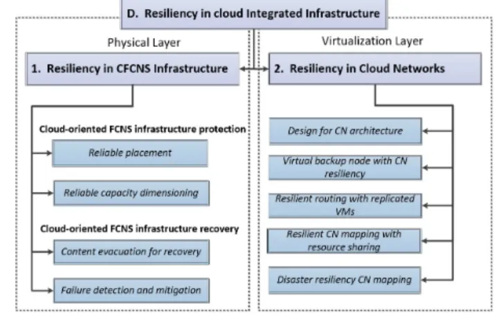
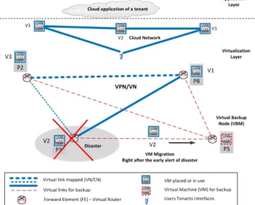
D. Resiliency in cloud integrated infrastructure
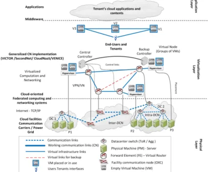
Cloud providers connect computation and communication elements in an integrated infrastructure to offer their services to tenants and customers. This integration results in a so-called Cloud Oriented Federated Computing and Networking System (CFCNS) [157]. Then, cloud functionalities (as seen in Section II-B) are enabled by virtualizing the CFCNS infras-tructure, i.e., slicing the CFNS resource, thanks to virtualized servers (i.e., VMs and VSs) that are accessed using virtualized networks (i.e., VN, VON, and SDN). In the following, we will call the integration of virtual servers and virtual networks as a Cloud Network (CN) [155], i.e., the CN is a virtualized slice of the CFCNS infrastructure (see Glossary in Section VIII). In such an integrated system, failures in network elements as well as in servers might induce failure cascades that affect other elements of the CFCNS, given their strict interdependence. So, resiliency techniques specifically designed for communication network or server systems in isolation can be insufficient to ensure the resiliency of a CFCNS. An efficient coordination and integration of these resiliency approaches is necessary.
![Fig. 7. Examples and comparison of network-centric vs. server-centric intra- intra-DCN architectures [86], [87]](https://thumb-us.123doks.com/thumbv2/123dok_us/10183517.2920837/10.918.469.855.717.858/examples-comparison-network-centric-server-centric-intra-architectures.webp)

![Fig. 9. Example of SVNE problem and two suggested techniques. a-b) Two virtual networks VN 1 = [1-2, 2-3, 1-3] (virtual links I, II, and III) and VN 2](https://thumb-us.123doks.com/thumbv2/123dok_us/10183517.2920837/13.918.102.421.94.668/example-svne-problem-suggested-techniques-virtual-networks-virtual.webp)