Programming manual
Altivar 31
Variable speed drives
for asynchronous motors
Contents
Warnings____________________________________________________________________________________________________ 2 Steps for setting up the starter ___________________________________________________________________________________ 3 Factory configuration __________________________________________________________________________________________ 4 Basic functions _______________________________________________________________________________________________ 5 Setup - Preliminary recommendations _____________________________________________________________________________ 7 Functions of the display and the keys______________________________________________________________________________ 8 Remote terminal option________________________________________________________________________________________ 10 Programming _______________________________________________________________________________________________ 11 Function compatibility _________________________________________________________________________________________ 13 List of functions which can be assigned to inputs/outputs _____________________________________________________________ 14 Settings menu SEt-___________________________________________________________________________________________ 16 Motor control menu drC-_______________________________________________________________________________________ 20 I/O menu I-O- _______________________________________________________________________________________________ 23 Control menu CtL- ___________________________________________________________________________________________ 26 Application functions menu FUn- ________________________________________________________________________________ 37 Fault menu FLt- _____________________________________________________________________________________________ 60 Communication menu COM- ___________________________________________________________________________________ 63 Display menu SUP- __________________________________________________________________________________________ 64 Maintenance ________________________________________________________________________________________________ 67 Faults - Causes - Remedies ____________________________________________________________________________________ 68 Configuration/Settings table ____________________________________________________________________________________ 70 Index of parameter codes ______________________________________________________________________________________ 74 Index of functions ____________________________________________________________________________________________ 75
Warnings
When the drive is powered up, the power components and some of the control components are connected to the line supply. It is extremely dangerous to touch them. The drive cover must be kept closed.
In general, the drive power supply must be disconnected before any operation on either the electrical or mechanical parts of the installation or machine.
After the ALTIVAR has been switched off and the display has disappeared completely, wait for 10 minutes before working on the equipment. This is the time required for the capacitors to discharge.
The motor can be stopped during operation by inhibiting start commands or the speed reference while the drive remains powered up. If personnel safety requires prevention of sudden restarts, this electronic locking system is not sufficient: fit a cut-off on the power circuit.
The drive is fitted with safety devices which, in the event of a fault, can shut down the drive and consequently the motor. The motor itself may be stopped by a mechanical blockage. Finally, voltage variations, especially line supply failures, can also cause shutdowns.
If the cause of the shutdown disappears, there is a risk of restarting which may endanger certain machines or installations, especially those which must conform to safety regulations.
In this case the user must take precautions against the possibility of restarts, in particular by using a low speed detector to cut off power to the drive if the motor performs an unprogrammed shutdown.
The drive must be installed and set up in accordance with both international and national standards. Bringing the device into conformity is the responsibility of the systems integrator who must observe the EMC directive among others within the European Union.
The specifications contained in this document must be applied in order to comply with the essential requirements of the EMC directive.
The Altivar 31 must be considered as a component: it is neither a machine nor a device ready for use in accordance with European directives (machinery directive and electromagnetic compatibility directive). It is the responsibility of the end user to ensure that the machine meets these standards.
The drive must not be used as a safety device for machines posing a potential risk of material damage or personal injury (lifting equipment, for example). In such applications, overspeed checks and checks to ensure that the trajectory remains under constant control must be made by separate devices which are independent of the drive.
The products and equipment described in this document may be changed or modified at any time, either from a technical point of view or in the way they are operated. Their description can in no way be considered contractual.
Steps for setting up the starter
1 - Delivery of the drive
• Check that the drive reference printed on the label is the same as that on the delivery note corresponding to the purchase order. • Remove the Altivar 31 from its packaging and check that it has not been damaged in transit.
2 - Check that the line voltage is compatible with the supply voltage range of the drive
(see the ATV 31Installation Manual).
- The drive may be damaged if the line voltage is not compatible.
3 - Fit the drive
4 - Connect the following to the drive:
• The line supply, ensuring that it is:
- compatible with the voltage range of the drive - switched off
• The motor, ensuring that its coupling corresponds to the line voltage • The control via the logic inputs
• The speed reference via the logic or analog inputs
5 - Switch on the drive, but do not give a run command
6 - Configure the following:
The nominal frequency (bFr) of the motor, if it is different from 50 Hz.
7 - Configure the following in the drC- menu:
The motor parameters, only if the factory configuration of the drive is not suitable.
8 - Configure the following in the I-O-, CtL- and FUn- menus:
The application functions (only if the factory configuration of the drive is not suitable), for example the control mode: 3-wire, or 2-wire transition detection, or 2-wire level detection, or 2-wire level detection with forward direction priority, or local control for ATV31pppA.
The user must ensure that the programmed functions are compatible with the wiring diagram used.
9 - Set the following in the SEt- menu:
- The ACC (Acceleration) and dEC (Deceleration) parameters
- The LSP (Low speed when the reference is zero) and HSP (High speed when the reference is maximum) parameters - The ItH parameter (Motor thermal protection)
10 - Start the drive
Practical recommendations
• Preparations can be made for programming the drive by filling in the configuration and settings tables (see page70), in particular when the factory configuration has to be changed.
• It is always possible to return to the factory settings using the FCS parameter in the drC-, I-O-, CtL- and FUn- menus (set InI to activate the function, see page22, 25, 36 or 59).
• Auto-tuning, which is performed using the drC- menu, can be applied to optimize performance in terms of accuracy and response time. Auto-tuning measures the stator resistance of the motor in order to optimize the control algorithms.
Factory configuration
Factory settings
The Altivar 31 is factory-set for the most common operating conditions:
• Display: Drive ready (rdY) with motor stopped, and motor frequency with motor running • Motor frequency (bFr): 50 Hz
• Constant torque application with sensorless flux vector control (UFt = n) • Normal stop mode on deceleration ramp (Stt = rMP).
• Stop mode in the event of a fault: Freewheel • Linear ramps (ACC, dEC): 3 seconds • Low speed (LSP): 0 Hz
• High speed (HSP): 50 Hz
• Motor thermal current (ItH) = nominal motor current (value depending on drive rating) • Standstill injection braking current (SdC) = 0.7 x nominal drive current, for 0.5 seconds • Automatic adaptation of the deceleration ramp in the event of overvoltage on braking • No automatic restarting after a fault
• Switching frequency 4 kHz • Logic inputs:
- LI1, LI2 (2 directions of operation): 2-wire transition detection control, LI1 = forward, LI2 = reverse, inactive on ATV 31ppppppA drives (not assigned)
- LI3, LI4: 4 preset speeds (speed 1 = speed reference or LSP, speed 2 = 10 Hz, speed 3 = 15 Hz, speed 4 = 20 Hz). - LI5 - LI6: Inactive (not assigned)
• Analog inputs:
- AI1: Speed reference 0-10 V, inactive on ATV 31ppppppA (not assigned) - AI2: Summed speed reference input 0±10 V
- AI3: 4-20 mA inactive (not assigned)
• Relay R1: The contact opens in the event of a fault (or drive off) • Relay R2: Inactive (not assigned)
• Analog output AOC: 0-20 mA inactive (not assigned)
ATV 31
pppppp
A range
When they leave the factory, ATV 31ppppppA drives are supplied with local control activated: the RUN, STOP buttons and the drive potentiometer are active. Logic inputs LI1 and LI2 and analog input AI1 are inactive (not assigned).
Basic functions
Drive thermal protection
Functions:
Thermal protection by PTC probe fitted on the heatsink or integrated in the power module.
Indirect protection of the drive against overloads by tripping in the event of an overcurrent. Typical tripping points: - Motor current = 185% of nominal drive current: 2 seconds
- Motor current = 150% of nominal drive current: 60 seconds
Drive ventilation
The fan starts up when the drive is powered up then shuts down after 10 seconds if a run command has not been received.
The fan is powered automatically when the drive is unlocked (operating direction + reference). It is powered down a few seconds after the drive is locked (motor speed < 0.2 Hz and injection braking completed).
1.1 1 1000 3000 5000 1.2 1.3 1.4 1.5 1.6 1.7 1.8 1.9 60 100 160 2 0 200 Time (seconds) Motor current/Drive In
Basic functions
Motor thermal protection
Function:
Thermal protection by calculating the I2t.
The protection takes account of self-cooled motors.
Caution: The memory of the motor thermal state returns to zero when the drive is disconnected.
10 000 1 000 100 0.7 0.8 0.9 1 1.1 1.2 1.3 1.4 1.5 1.6 50 Hz 20 Hz 10 Hz 1 Hz 3 Hz 5 Hz Trip time t in seconds Motor current/ItH
Setup - Preliminary recommendations
Prior to switching on and configuring the drive
With power switching via line contactor
User adjustment and extension of functions
If necessary, the display and buttons can be used to modify the settings and to extend the functions described in the following pages. It is very easy to return to the factory settings using the FCS parameter in the drC-, I-O-, CtL- and FUn- menus (set InI to activate the function, see page22, 25, 36 or 59).
There are three types of parameter: - Display: Values displayed by the drive
- Setting: Can be changed during operation or when stopped
- Configuration: Can only be modified when stopped and no braking is taking place. Can be displayed during operation.
Start up
Important: In factory settings mode on power-up, or in a manual fault reset or after a stop command, the motor can only be powered once the "forward", "reverse" and "DC injection stop" commands have been reset. If they have not been reset, the drive will display "nSt" but will not start. If the automatic restart function is configured (parameter Atr in the FLt- menu, see page60), these commands are taken into account without a reset being necessary.
Test on a low power motor or without a motor
• In factory settings mode, "motor phase loss" detection is active (OPL = YES). To check the drive in a test or maintenance environment without having to switch to a motor with the same rating as the drive (particularly useful in the case of high power drives), deactivate "motor phase loss" detection (OPL = NO).
• Configure the voltage/frequency ratio: UFt = L (drC- menu on page 21)
Using motors in parallel
• Configure the voltage/frequency ratio: UFt = L (drC- menu on page 21)
- Check that the line voltage is compatible with the supply voltage range of the drive (see pages 3 and 4 of the ATV 31 Installation Manual). The drive may be damaged if the line voltage is not compatible.
- Ensure the logic inputs are switched off (state 0) to prevent accidental starting. Otherwise, an input assigned to the run command may cause the motor to start immediately on exiting the configuration menus.
- Avoid operating the contactor frequently (premature ageing of the filter capacitors). Use inputs LI1 to LI6 to control the drive.
- These instructions are vital for cycles < 60 s, otherwise the load resistor may be damaged.
- Check that changes to the current operating settings do not present any danger. Changes should preferably be made with the drive stopped.
• Motor thermal protection will not be provided by the drive if the motor current is less than 0.2 times the nominal drive current.
Functions of the display and the keys
• Pressing or does not store the selection.
• Press and hold down (>2 s) or to scroll through the data quickly. To save and store the selection: ENT
The display flashes when a value is stored.
Normal display, with no fault present and no starting:
- 43.0: Display of the parameter selected in the SUP- menu (default selection: motor frequency). In current limit mode, the display flashes.
- init: Initialization sequence - rdY: Drive ready
- dcb: DC injection braking in progress - nSt: Freewheel stop
- FSt: Fast stop
- tUn: Auto-tuning in progress
The display flashes to indicate the presence of a fault.
Altivar 31 ESC ENT RUN ERR CAN
• Four 7-segment displays
• Enters a menu or a parameter, or saves the displayed parameter or value • Returns to the previous
menu or parameter, or increases the displayed value
• Exits a menu or parameter, or clears the displayed value to return to the previous stored value
• Goes to the next menu or parameter, or decreases the displayed value • Red LED
"DC bus ON"
Functions of the display and the keys
ATV31
pppppp
A:
• Pressing or does not store the selection.
• Press and hold down (>2 s) or to scroll through the data quickly.
To save and store the selection: ENT The display flashes when a value is stored.
Normal display, with no fault present and no starting:
- 43.0: Display of the parameter selected in the SUP- menu (default selection: output frequency applied to the motor). In current limit mode, the display flashes.
- init: Initialization sequence - rdY: Drive ready
- dcb: DC injection braking in progress - nSt: Freewheel stop
- FSt: Fast stop
- tUn: Auto-tuning in progress
The display flashes to indicate the presence of a fault.
Altivar 31 RUN ESC ENT
STOP
RESET
RUN ERR CAN • Reference potentiometer, active if the Fr1 parameter in the CtL- menu is configured as AIP • Four 7-segment displays• Enters a menu or a parameter, or saves the displayed parameter or value
• Returns to the previous menu or parameter, or increases the displayed value
• Exits a menu or a parameter,
or clears the displayed value to return to the previous stored value
• Goes to the next menu or parameter, or decreases the displayed value
STOP/RESET button • Used to reset faults
• Can be used to control motor stopping - If tCC (I-O- menu) is not configured
as LOC, it is a freewheel stop. - If tCC (I-O- menu) is configured as
LOC, stopping is on a ramp, but if injection braking is in progress, a freewheel stop takes place. • RUN button: Controls motor
switch-on in forward mode, if parameter tCC in the I-O- menu is configured as LOC
• Red LED "DC bus ON"
Remote terminal option
This module is a local control unit which can be mounted on the door of the wall-mounted or floor-standing enclosure. It has a cable with connectors, which is connected to the drive serial link (see the manual supplied with the terminal). It has the same display and the same programming buttons as the Altivar 31 with the addition of a switch to lock access to the menus and three buttons for controlling the drive: • FWD/REV: reversal of the direction of rotation
• RUN: motor run command
• STOP/RESET: Motor stop command or fault reset
Pressing the button a first time stops the motor, and if DC injection standstill braking is configured, pressing it a second time stops this braking.
View of the front panel: View of the rear panel:
Note: Customer password protection has priority on the switch.
Saving and loading configurations
Up to four complete configurations for ATV 31 drives can be stored on the remote terminal. These configurations can be saved, transported and transferred from one drive to another of the same rating. 4 different operations for the same device can also be stored on the terminal. See the SCS and FCS parameters in the drC-, I-O-, CtL- and FUn- menus.
• The access locking switch on the remote terminal also prevents the drive settings being accessed via the keypad. • When the remote terminal is disconnected, if the drive has been locked, the keypad will remain locked.
• In order for the remote terminal to be active, the tbr parameter in the COM- menu must remain in factory settings mode: 19.2 (see page 73).
ESC
ENT
RUN
FWD REV STOP RESET 4-character display unit ConnectorAccess locking switch:
• positions: settings and display accessible (SEt- and SUP- menus)
Programming
Access to menus
Some parameters can be accessed in a number of menus for increased user-friendliness: - Entering settings
- Return to factory settings
- Restoring and saving the configuration
A dash appears after menu and sub-menu codes to differentiate them from parameter codes. Examples: FUn- menu, ACC parameter.
XXX bFr FLt- SUP- CON- SEt- FUn- CtL- I-O- drC-ESC ESC ESC ESC ESC ESC ESC ESC ESC ENT ENT ENT ESC ENT ESC ENT ESC ENT ESC ENT ESC ENT ESC ENT ESC ENT ESC
Displays the drive status
Motor frequency (the factory setting is only visible the first time the drive is powered up)
Motor control Faults Communication Monitoring Settings Menus I/O Control Functions Power-up
Programming
Accessing menu parameters
To save and store the selection: The display flashes when a value is stored. Example:
All the menus are "drop-down" type menus, which means that after the last parameter, if you continue to press , you will return to the first parameter and, conversely, you can switch from the first parameter to the last parameter by pressing .
If, after modifying any of the parameters (nth), you quit a menu and return to this menu without having accessed another menu in the meantime, you will be taken directly to the nth parameter (see below). If, in the meantime, you have accessed another menu or have restarted the system, you will always be taken to the first parameter in the menu (see above).
Configuration of the bFr parameter
This parameter can only be modified in stop mode without a run command.
Code Description Adjustment
range Factory setting
bFr Standard motor frequency 50
This parameter is only visible the first time the drive is switched on. It can be modified at any time in the drC- menu.
50 Hz: IEC 60 Hz: NEMA
This parameter modifies the presets of the following parameters: HSP page 16, Ftd page 19, FrS page 20 and tFr page
22. ENT ACC 15.0 ENT ESC ENT ESC 26.0 26.0 ESC dEC ENT
SEt-Menu Value or assignment
1 flash (save) Parameter (Next parameter) ENT ESC 1st nth last Menu ENT ESC 1st nth last Menu
>.H
Function compatibility
Incompatible functions
The following functions will be inaccessible or deactivated in the cases described below:
Automatic restart
This is only possible for 2-wire level detection control (tCC = 2C and tCt = LEL or PFO).
Flying restart
This is only possible for 2-wire level detection control (tCC = 2C and tCt = LEL or PFO). This function is locked if automatic standstill injection is configured as DC (AdC = Ct).
Reverse
On the ATV31pppA range only, this function is locked if local control is active (tCC = LOC).
Function compatibility table
The choice of application functions may be limited by the number of I/O and by the fact that some functions are incompatible with one another. Functions which are not listed in this table are fully compatible.
If there is an incompatibility between functions, the first function configured will prevent the remainder being configured.
(1) Excluding special application with reference channel Fr2 (see diagrams 28 and 30)
Priority functions (functions which cannot be active simultaneously):
Stop functions have priority over run commands.
Speed references via logic command have priority over analog references.
Logic and analog input application functions
Summi ng i nput s +/ - spe ed (1) Manag ement of l imi t swit che s Prese t spe eds PI r e gu la to r Jog ope ra tion Brake se quen ce DC in ject ion st op Fas t st op Freewhe el st op Summing inputs
p
A
p
A
+/- speed (1)p
p
p
p
Management of limit switches
p
Preset speeds
X
p
p
A
PI regulatorp
p
p
p
p
p
Jog operationX
p
X
p
p
Brake sequencep
p
p
DC injection stopp
A
Fast stopA
Freewheel stopX
X
p
Incompatible functions Compatible functions Not applicableList of functions which can be assigned to inputs/outputs
Logic inputs Page Code Factory setting
ATV31ppp ATV31pppA
Not assigned - - LI5 - LI6 LI1 - LI2
LI5 - LI6
Forward - - LI1
2 preset speeds 44 PS2 LI3 LI3
4 preset speeds 44 PS4 LI4 LI4
8 preset speeds 44 PS8 16 preset speeds 45 PS16 2 preset PI references 51 Pr2 4 preset PI references 51 Pr4 + speed 48 USP - speed 48 dSP
Jog operation 46 JOG
Ramp switching 38 rPS
Switching for 2nd current limit 55 LC2
Fast stop via logic input 39 FSt
DC injection via logic input 39 dCI
Freewheel stop via logic input 40 nSt
Reverse 23 rrS LI2
External fault 61 EtF
RESET (fault reset) 60 rSF
Forced local mode 63 FLO
Reference switching 34 rFC
Control channel switching 35 CCS
Motor switching 56 CHP
Limiting of forward motion (limit switch) 58 LAF
Limiting of reverse motion (limit switch) 58 LAr
Fault inhibit 62 InH
Analog inputs Page Code Factory setting
ATV31ppp ATV31pppA
Not assigned - - AI3 AI1 - AI3
Reference 1 33 Fr1 AI1 AIP
(potentiometer)
Reference 2 33 Fr2
Summing input 2 42 SA2 AI2 AI2
Summing input 3 42 SA3
PI regulator feedback 51 PIF
Analog/logic output Page Code Factory setting
Not assigned - - AOC/AOV
Motor current 24 OCr
Motor frequency 24 rFr
Motor torque 24 OLO
Power supplied by the drive 24 OPr
Drive fault (logic data) 24 FLt
Drive running (logic data) 24 rUn
Frequency threshold reached (logic data) 24 FtA
High speed (HSP) reached (logic data) 24 FLA
Current threshold reached (logic data) 24 CtA
Frequency reference reached (logic data) 24 SrA
List of functions which can be assigned to inputs/outputs
Relay Page Code Factory setting
Not assigned - - R2
Drive fault 24 FLt R1
Drive running 24 rUn
Frequency threshold reached 24 FtA
High speed (HSP) reached 24 FLA
Current threshold reached 24 CtA
Frequency reference reached 24 SrA
Motor thermal threshold reached 24 tSA
Settings menu
SEt-The adjustment parameters can be modified with the drive running or stopped.
Check that it is safe to make changes during operation. Changes should preferably be made in stop mode.
(1) In corresponds to the nominal drive current indicated in the Installation Manual and on the drive rating plate. These parameter appear regardless of how the other menus have been configured.
These parameters only appear if the corresponding function has been selected in another menu. When the corresponding function is also accessible and adjustable from within the configuration menu, to aid programming their description is detailed in these menus, on the pages indicated.
Code Description Adjustment
range Factory setting LFr Speed reference via the remote terminal 0 to HSP
This parameter appears if LCC = YES (page 35) or if Fr1/Fr2 = LCC (page 33), and if the remote terminal is online. In this case, LFr can also be accessed via the drive keypad.
LFr is reset to 0 when the drive is powered down.
rPI Internal PI regulator reference See page51 0.0 to 100% 0
ACC Acceleration ramp time 0.1 to 999.9 s 3 s
Defined as the acceleration time between 0 and the nominal frequency FrS (parameter in the drC- menu).
AC2 2nd acceleration ramp time See page38 0.1 to 999.9 s 5 s
dE2 2nd deceleration ramp time See page38 0.1 to 999.9 s 5 s
dEC Deceleration ramp time 0.1 to 999.9 s 3 s
Defined as the deceleration time between the nominal frequency FrS (parameter in the drC- menu) and 0. Check that the value of dEC is not too low in relation to the load to be stopped.
tA1 Start of CUS-type acceleration ramp rounded
as % of total ramp time (ACC or AC2) See page37 0 to 100 10% tA2 End of CUS-type acceleration ramp rounded
as % of total ramp time (ACC or AC2) See page37 0 to (100-tA1) 10% tA3 Start of CUS-type deceleration ramp rounded
as % of total ramp time (dEC or dE2) See page37 0 to 100 10% tA4 End of CUS-type deceleration ramp rounded
as % of total ramp time (dEC or dE2) See page37 0 to (100-tA3) 10%
LSP Low speed 0 to HSP 0 Hz
(Motor frequency at min. reference)
HSP High speed LSP to tFr bFr
(Motor frequency to max. reference): Check that this setting is suitable for the motor and the application.
ItH Motor thermal protection - max. thermal current 0.2 to 1.5 In (1) According to drive rating
Set ItH to the nominal current on the motor rating plate.
Please refer to OLL on page 61 if you wish to suppress thermal protection.
rPI LFr SEt-ACC SdS ENT ENT ESC ESC ENT ESC ESC ESC ESC ENT ESC ENT ESC
Speed reference via the terminal
Spd parameter scale factor
Settings menu
SEt-(1) In corresponds to the nominal drive current indicated in the Installation Manual and on the drive rating plate. Code Description Adjustment
range
Factory setting UFr IR compensation/voltage boost 0 to 100% 20
- For UFt (page 21) = n or nLd: IR compensation - For UFt = L or P: Voltage boost
Used to optimize the torque at very low speed (increase UFr if the torque is insufficient). Check that the value of UFr is not too high for when the motor is warm (risk of instability).
Modifying UFt (page 21) will cause UFr to return to the factory setting (20%).
FLG Frequency loop gain 1 to 100% 20 Parameter can only be accessed if UFt (page 21) = n or nLd.
The FLG parameter adjusts the drive’s ability to follow the speed ramp based on the inertia of the machine being driven.
Too high a gain may result in operating instability.
StA Frequency loop stability 1 to 100% 20 Parameter can only be accessed if UFt (page 21) = n or nLd.
Used to adapt the return to steady state after a speed transient (acceleration or deceleration), according to the dynamics of the machine.
Gradually increase the stability to avoid any overspeed.
SLP Slip compensation 0 to 150% 100 Parameter can only be accessed if UFt (page 21) = n or nLd.
Used to adjust the slip compensation value fixed by nominal motor speed. The speeds given on motor rating plates are not necessarily exact.
• If slip setting < actual slip: the motor is not rotating at the correct speed in steady state. • If slip setting > actual slip: the motor is overcompensated and the speed is unstable.
IdC Level of DC injection braking current activated via logic input or selected as stop mode (2).
See page39 0 to In (1) 0.7 In (1)
tdC Total DC injection braking time selected as stop mode (2).
See page39 0.1 to 30 s 0.5 s
tdC1 Automatic standstill DC injection time See page41 0.1 to 30 s 0.5 s
SdC1 Level of automatic standstill DC injection current See page41 0 to 1.2 In (1) 0.7 In (1)
tdC2 2nd automatic standstill DC injection time See page41 0 to 30 s 0 s
SdC2 2nd level of standstill DC injection current See page41 0 to 1.2 In (1) 0.5 In (1)
SEt-0 0.1 0.2 0.3 0.4 0.5 -10 10 20 30 40 0 50 0 0.1 0.2 0.3 0.4 0.5 -10 10 20 30 40 0 50 0 0.1 0.2 0.3 0.4 0.5 -10 10 20 30 40 0 50 t Hz t Hz t HzFLG low FLG correct FLG high
In this case,
increase FLG In this case, reduce FLG
0 0.1 0.2 0.3 0.4 0.5 t -10 10 20 30 40 0 50 Hz 0 0.1 0.2 0.3 0.4 0.5 t -10 10 20 30 40 0 50 Hz 0 0.1 0.2 0.3 0.4 0.5 t -10 10 20 30 40 0 50 Hz
StA low StA correct StA high
In this case, increase StA
In this case, reduce StA
Settings menu
SEt-(1) In corresponds to the nominal drive current indicated in the Installation Manual and on the drive rating plate. Code Description Adjustment
range
Factory setting JPF Skip frequency 0 to 500 0 Hz
Prevents prolonged operation at a frequency range of ± 1 Hz around JPF. This function prevents a critical speed which leads to resonance. Setting the function to 0 renders it inactive.
JF2 2nd skip frequency 0 to 500 0 Hz
Prevents prolonged operation at a frequency range of ± 1 Hz around JF2. This function prevents a critical speed which leads to resonance. Setting the function to 0 renders it inactive.
JGF Jog operating frequency See page46 0 to 10 Hz 10 Hz
rPG PI regulator proportional gain See page51 0.01 to 100 1
rIG PI regulator integral gain See page51 0.01 to 100/s 1/s
FbS PI feedback multiplication coefficient See page51 0.1 to 100 1
PIC Reversal of the direction of correction of the PI
regulator See page51 nO - YES nO rP2 2nd preset PI reference See page51 0 to 100% 30%
rP3 3rd preset PI reference See page51 0 to 100% 60%
rP4 4th preset PI reference See page51 0 to 100% 90%
SP2 2nd preset speed See page45 0 to 500 Hz 10 Hz
SP3 3rd preset speed See page45 0 to 500 Hz 15 Hz
SP4 4th preset speed See page45 0 to 500 Hz 20 Hz
SP5 5th preset speed See page45 0 to 500 Hz 25 Hz
SP6 6th preset speed See page45 0 to 500 Hz 30 Hz
SP7 7th preset speed See page45 0 to 500 Hz 35 Hz
SP8 8th preset speed See page45 0 to 500 Hz 40 Hz
SP9 9th preset speed See page45 0 to 500 Hz 45 Hz
SP10 10th preset speed See page45 0 to 500 Hz 50 Hz
SP11 11th preset speed See page45 0 to 500 Hz 55 HZ
SP12 12th preset speed See page45 0 to 500 Hz 60 Hz
SP13 13th preset speed See page45 0 to 500 Hz 70 Hz
SP14 14th preset speed See page45 0 to 500 Hz 80 Hz
SP15 15th preset speed See page45 0 to 500 Hz 90 Hz
SP16 16th preset speed See page45 0 to 500 Hz 100 Hz
CLI Current limit 0.25 to 1.5 In (1) 1.5 In (1) Used to limit the torque and the temperature rise of the motor.
CL2 2nd current limit See page55 0.25 to 1.5 In (1) 1.5 In (1)
tLS Low speed operating time 0 to 999.9 s 0 (no time limit) Following operation at LSP for a defined period, a motor stop is requested automatically. The motor restarts if the frequency reference is greater than LSP and if a run command is still present.
Caution: Value 0 corresponds to an unlimited time
rSL Restart error threshold ("wake-up" threshold) See page52 0 to 100% 0
UFr2 IR compensation, motor 2 See page57 0 to 100% 20
FLG2 Frequency loop gain, motor 2 See page57 1 to 100% 20
StA2 Stability, motor 2 See page57 1 to 100% 20
SLP2 Slip compensation, motor 2 See page57 0 to 150% 100%
These parameters only appear if the corresponding function has been selected in another menu. When the corresponding function is also accessible and adjustable from within the configuration menu, to aid programming their description is detailed in these menus, on the pages indicated.
Those which are underlined appear in factory settings mode.
Settings menu
SEt-(1) In corresponds to the nominal drive current indicated in the Installation Manual and on the drive rating plate. Code Description Adjustment
range
Factory setting Ftd Motor frequency threshold above which the relay contact
(R1 or R2 = FtA) closes or output AOV = 10 V (dO = StA)
0 to 500 Hz bFr
ttd Motor thermal state threshold above which the relay contact (R1 or R2 = tSA) closes or output AOV = 10 V (dO = tSA)
0 to 118% 100%
Ctd Motor current threshold beyond which the relay contact (R1 or R2 = CtA) closes or output AOV = 10 V (dO = CtA)
0 to 1.5 In (1) In (1)
SdS Scale factor for display parameter SPd1/SPd2/SPd3 (SUP- menu on page 65)
0.1 to 200 30
Used to scale a value in proportion to the output frequency rFr: the machine speed, the motor speed, etc. - If SdS y 1, SPd1 is displayed (possible definition = 0.01)
- If 1 < SdS y 10, SPd2 is displayed (possible definition = 0.1) - If SdS > 10, SPd3 is displayed (possible definition = 1) - If SdS > 10 and SdS x rFr > 9999:
Display of Spd3 = to 2 decimal places
Example: For 24 223, display is 24.22
- If SdS > 10 and SdS x rFr > 65535, display locked at 65.54 Example: Display motor speed for
4-pole motor, 1500 rpm at 50 Hz (synchronous speed): SdS = 30
SPd3 = 1500 at rFr = 50 Hz
SFr Switching frequency See page 22 2.0 to 16 kHz 4 kHz This parameter can also be accessed in the drC- menu.
SEt-SdS x rFr 1000
Motor control menu
drC-With the exception of tUn, which can power up the motor, parameters can only be modified in stop mode, with no run command present.
On the optional remote terminal, this menu can be accessed with the switch in the position. Drive performance can be optimized by:
- Entering the values given on the motor rating plate in the drive menu - Performing an auto-tune operation (on a standard asynchronous motor)
(1) In corresponds to the nominal drive current indicated in the Installation Manual and on the drive rating plate. Code Description Adjustment
range Factory setting
bFr Standard motor frequency 50
50 Hz: IEC 60 Hz: NEMA
This parameter modifies the presets of the following parameters: HSP page 16, Ftd page 19, FrS page 20 and tFr page22.
UnS Nominal motor voltage given on the rating plate According to drive
rating According to drive rating ATV31pppM2: 100 to 240 V
ATV31pppM3X: 100 to 240 V ATV31pppN4: 100 to 500 V ATV31pppS6X: 100 to 600 V
FrS Nominal motor frequency given on the rating plate 10 to 500 Hz 50 Hz
The ratio must not exceed the following values:
ATV31pppM2: 7 max. ATV31pppM3X: 7 max. ATV31pppN4: 14 max. ATV31pppS6X: 17 max.
The factory setting is 50 Hz, or preset to 60 Hz if bFr is set to 60 Hz.
nCr Nominal motor current given on the rating plate 0.25 to 1.5 In (1) According to drive rating
nSP Nominal motor speed given on the rating plate 0 to 32760 RPM According to drive rating
0 to 9999 RPM then 10.00 to 32.76 KRPM
If, rather than the nominal speed, the rating plate indicates the synchronous speed and the slip in Hz or as a %, calculate the nominal speed as follows:
• Nominal speed = Synchronous speed x or
• Nominal speed = Synchronous speed x (50 Hz motors)
or
• Nominal speed = Synchronous speed x (60 Hz motors)
COS Motor Cos Phi given on the rating plate 0.5 to 1 According to drive rating ESC ENT bFr ENT ESC ENT ESC FCS ESC ESC drC-tAI
Standard motor frequency
Return to factory settings/restore configuration
drC-UnS (in volts) FrS (in Hz) 100 - slip as a % 100 50 - slip in Hz 50 60 - slip in Hz 60
Motor control menu
drC-Code Description Adjustment
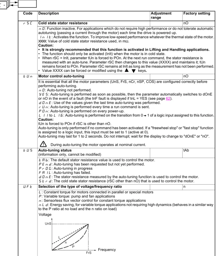
range Factory setting rSC Cold state stator resistance nO
nO: Function inactive. For applications which do not require high performance or do not tolerate automatic autotuning (passing a current through the motor) each time the drive is powered up.
InIt: Activates the function. To improve low-speed performance whatever the thermal state of the motor.
XXXX: Value of cold state stator resistance used, in mΩ. Caution:
• It is strongly recommended that this function is activated in Lifting and Handling applications. • The function should only be activated (InIt) when the motor is in cold state.
• When rSC = InIt, parameter tUn is forced to POn. At the next run command, the stator resistance is measured with an auto-tune. Parameter rSC then changes to this value (XXXX) and maintains it; tUn remains forced to POn. Parameter rSC remains at InIt as long as the measurement has not been performed. • Value XXXX can be forced or modified using the keys.
tUn Motor control auto-tuning nO
It is essential that all the motor parameters (UnS, FrS, nCr, nSP, COS) are configured correctly before performing auto-tuning.
nO: Auto-tuning not performed.
YES: Auto-tuning is performed as soon as possible, then the parameter automatically switches to dOnE or nO in the event of a fault (the tnF fault is displayed if tnL = YES (see page62).
dOnE: Use of the values given the last time auto-tuning was performed.
rUn: Auto-tuning is performed every time a run command is sent.
POn: Auto-tuning is performed on every power-up.
LI1 to LI6: Auto-tuning is performed on the transition from 0 V 1 of a logic input assigned to this function. Caution:
tUn is forced to POn if rSC is other than nO.
Auto-tuning is only performed if no command has been activated. If a "freewheel stop" or "fast stop" function is assigned to a logic input, this input must be set to 1 (active at 0).
Auto-tuning may last for 1 to 2 seconds. Do not interrupt; wait for the display to change to "dOnE" or "nO". During auto-tuning the motor operates at nominal current.
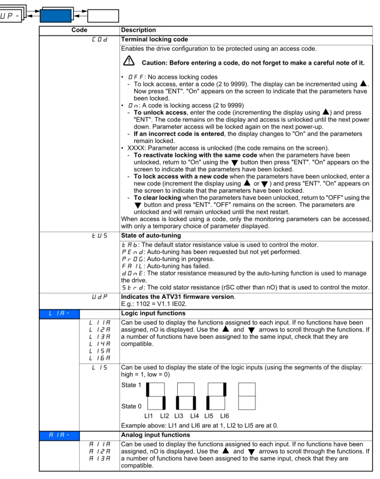
tUS Auto-tuning status
(information only, cannot be modified) tAb
tAb: The default stator resistance value is used to control the motor.
PEnd: Auto-tuning has been requested but not yet performed.
PrOG: Auto-tuning in progress
FAIL: Auto-tuning has failed.
dOnE: The stator resistance measured by the auto-tuning function is used to control the motor.
Strd: The cold state stator resistance (rSC other than nO) that is used to control the motor.
UFt Selection of the type of voltage/frequency ratio n
L: Constant torque for motors connected in parallel or special motors
P: Variable torque: pump and fan applications
n: Sensorless flux vector control for constant torque applications
nLd: Energy saving, for variable torque applications not requiring high dynamics (behaves in a similar way to the P ratio at no load and the n ratio on load)
drC-L UnS FrS n P Voltage FrequencyMotor control menu
drC-Code Description Adjustment
range Factory setting nrd Random switching frequency YES
YES: Frequency with random modulation
nO: Fixed frequency
Random frequency modulation prevents any resonance which may occur at a fixed frequency.
SFr Switching frequency
(1) 2.0 to 16 kHz 4 kHz
The frequency can be adjusted to reduce the noise generated by the motor.
If the frequency has been set to a value higher than 4 kHz, in the event of an excessive rise in temperature, the drive will automatically reduce the switching frequency and increase it again once the temperature has returned to normal.
tFr Maximum output frequency 10 to 500 Hz 60 Hz The factory setting is 60 Hz, or preset to 72 Hz if bFr is set to 60 Hz.
SrF Suppression of the speed loop filter nO
nO: The speed loop filter is active (prevents the reference being exceeded).
YES: The speed loop filter is suppressed (in position control applications, this reduces the response time and the reference may be exceeded).
SCS Saving the configuration
(1) nO
nO: Function inactive
StrI: Saves the current configuration (but not the result of auto-tuning) to EEPROM. SCS automatically switches to nO as soon as the save has been performed. This function is used to keep another configuration in reserve, in addition to the current configuration.
When drives leave the factory the current configuration and the backup configuration are both initialized with the factory configuration.
• If the remote terminal option is connected to the drive, the following additional selection options will appear: FIL1, FIL2, FIL3, FIL4 (files available in the remote terminal's EEPROM memory for saving the current configuration). They can be used to store between 1 and 4 different configurations which can also be stored on or even transferred to other drives of the same rating.
SCS automatically switches to nO as soon as the save has been performed.
FCS Return to factory settings/restore configuration
(1) nO
nO: Function inactive
rECI: The current configuration becomes identical to the backup configuration previously saved by SCS = StrI. rECI is only visible if the backup has been carried out. FCS automatically changes to nO as soon as this action has been performed.
InI: The current configuration becomes identical to the factory setting. FCS automatically changes to nO as soon as this action has been performed.
• If the remote terminal option is connected to the drive, the following additional selection options appear, as long as the corresponding files have been loaded in the remote terminal's EEPROM memory (0 to 4 files): FIL1, FIL2, FIL3, FIL4. They enable the current configuration to be replaced with one of the 4 configurations which may be loaded on the remote terminal.
FCS automatically changes to nO as soon as this action has been performed.
Caution: If nAd appears on the display briefly once the parameter has switched to nO, this means that the configuration transfer is not possible and has not been performed (different drive ratings for example). If ntr appears on the display briefly once the parameter has switched to nO, this means that a configuration transfer error has occurred and the factory settings must be restored using InI. In both cases, check the configuration to be transferred before trying again.
For rECI, InI and FL1 to FL4 to be taken into account, the ENT key must be held down for 2 s.
I/O menu I-O-
The parameters can only be modified when the drive is stopped and no run command is present. On the optional remote terminal, this menu can be accessed with the switch in the position.
Code Description Factory setting
tCC 2-wire/3-wire control (Type of control) 2C ATV31pppA: LOC Control configuration: 2C = 2-wire control 3C = 3-wire control
LOC = local control (drive RUN/STOP/RESET) for ATV31pppA only (invisible if LAC = L3, see page 33). 2-wire control: The open or closed state of the input controls running or stopping.
Wiring example: LI1: forward LIx: reverse
3-wire control (pulse control): A "forward" or "reverse" pulse is sufficient to control starting, a "stop" pulse is sufficient to control stopping.
Example of wiring: LI1: stop
LI2: forward LIx: reverse
To change the assignment of tCC press the "ENT" key for 2 s. This causes the following functions to return to their factory setting: rrS, tCt and all functions affecting logic inputs.
tCt Type of 2-wire control (parameter only accessible if tCC = 2C) trn
LEL: State 0 or 1 is taken into account for run or stop.
trn: A change of state (transition or edge) is necessary to initiate operation, in order to prevent accidental restarts after a break in the power supply.
PFO: State 0 or 1 is taken into account for run or stop, but the "forward" input always takes priority over the "reverse" input.
rrS Reverse operation via logic input if tCC = 2C: LI2 if tCC = 3C: LI3 if tCC = LOC: nO If rrS = nO, reverse operation is active, by means of negative voltage on AI2 for example.
nO: Not assigned
LI2: Logic input LI2, can be accessed if tCC = 2C
LI3: Logic input LI3 ESC ENT tCC ENT ESC ENT ESC FCS ESC ESC
I-O- 2-wire/3-wire control
Return to factory settings/restore configuration
I-O-24 V LI1 LIx ATV 31
24 V LI1 LI2 LIx ATV 31
I/O menu I-O-
Code Description Factory setting
CrL3 CrH3
Value for low speed (LSP) on input AI3, can be set between 0 and 20 mA
Value for high speed (HSP) on input AI3, can be set between 4 and 20 mA 4 mA20 mA These two parameters are used to configure the input for 0-20 mA, 4-20 mA, 20-4 mA, etc.
AO1t Configuration of the analog output 0A
0A: 0 - 20 mA configuration (use terminal AOC)
4A: 4 - 20 mA configuration (use terminal AOC)
10U: 0 - 10 V configuration (use terminal AOV)
dO Analog/logic output AOC/AOV nO
nO: Not assigned
OCr: Motor current. 20 mA or 10 V corresponds to twice the nominal drive current.
OFr: Motor frequency. 20 mA or 10 V corresponds to the maximum frequency tFr (page 22).
Otr: Motor torque. 20 mA or 10 V corresponds to twice the nominal motor torque.
OPr: Power supplied by the drive. 20 mA or 10 V corresponds to twice the nominal drive power.
Making the following assignments (1) will transform the analog output to a logic output (see the diagram in the Installation Manual):
FLt: Drive fault
rUn: Drive running
FtA: Frequency threshold reached (Ftd parameter in the SEt- menu, page 19)
FLA: High speed (HSP) reached
CtA: Current threshold reached (Ctd parameter in the SEt- menu, page 19)
SrA: Frequency reference reached
tSA: Motor thermal threshold reached (ttd parameter in the SEt- menu, page 19)
bLC: Brake sequence (for information, as this assignment can be only be activated or deactivated from the FUn- menu, see page 54)
APL: Loss of 4-20 mA signal, even if LFL = nO (page 62)
The logic output is in state 1 (24 V) when the selected assignment is active, with the exception of FLt (state 1 if the drive is not faulty).
(1) With these assignments, configure AOt = 0A.
r1 Relay r1 FLt
nO: Not assigned
FLt: Drive fault
rUn: Drive running
FtA: Frequency threshold reached (Ftd parameter in the SEt- menu, page 19)
FLA: High speed (HSP) reached
CtA: Current threshold reached (Ctd parameter in the SEt- menu, page 19)
SrA: Frequency reference reached
tSA: Motor thermal threshold reached (ttd parameter in the SEt- menu, page 19)
APL: Loss of 4-20 mA signal, even if LFL = nO (page 62)
The relay is powered up when the selected assignment is active, with the exception of FLt (powered up if the drive is not faulty).
r2 Relay r2 nO
nO: Not assigned
FLt: Drive fault
rUn: Drive running
FtA: Frequency threshold reached (Ftd parameter in the SEt- menu, page 19)
FLA: High speed (HSP) reached
CtA: Current threshold reached (Ctd parameter in the SEt- menu, page 19)
SrA: Frequency reference reached
tSA: Motor thermal threshold reached (ttd parameter in the SEt- menu, page 19)
bLC: Brake sequence (for information, as this assignment can be only be activated or deactivated from the FUn- menu, see page 54)
APL: Loss of 4-20 mA signal, even if LFL = nO (page 62)
The relay is powered up when the selected assignment is active, with the exception of FLt (powered up if
I-O-AI 3 (mA) 0 LSP HSP CrL3 CrH3 20 AI 3(mA) 0 LSP HSP CrL3 CrH3 (20 mA) (4 mA) Frequency Frequency Example: 20 - 4 mAI/O menu I-O-
(1) SCS and FCS can be accessed via several configuration menus but they concern all menus and parameters as a whole.
Code Description Factory setting
SCS Saving the configuration (1)
nO: Function inactive
StrI: Saves the current configuration (but not the result of auto-tuning) to EEPROM. SCS automatically switches to nO as soon as the save has been performed. This function is used to keep another configuration in reserve, in addition to the current configuration.
When drives leave the factory the current configuration and the backup configuration are both initialized with the factory configuration.
• If the remote terminal option is connected to the drive, the following additional selection options will appear: FIL1, FIL2, FIL3, FIL4 (files available in the remote terminal's EEPROM memory for saving the current configuration). They can be used to store between 1 and 4 different configurations which can also be stored on or even transferred to other drives of the same rating.
SCS automatically switches to nO as soon as the save has been performed.
FCS Return to factory settings/restore configuration (1)
nO: Function inactive
rECI: The current configuration becomes identical to the backup configuration previously saved by SCS = StrI. rECI is only visible if the backup has been carried out. FCS automatically changes to nO as soon as this action has been performed.
InI: The current configuration becomes identical to the factory setting. FCS automatically changes to nO as soon as this action has been performed.
• If the remote terminal option is connected to the drive, the following additional selection options appear, as long as the corresponding files have been loaded in the remote terminal's EEPROM memory (0 to 4 files): FIL1, FIL2, FIL3, FIL4. They enable the current configuration to be replaced with one of the 4 configurations that may be loaded on the remote terminal.
FCS automatically changes to nO as soon as this action has been performed.
Caution: If nAd appears on the display briefly once FCS has switched to nO, this means that the configuration transfer is not possible and has not been performed (different drive ratings for example). If
ntr appears on the display briefly once the parameter has switched to nO, this means that a configuration transfer error has occurred and the factory settings must be restored using InI. In both cases, check the configuration to be transferred before trying again.
For rECI, InI and FL1 to FL4 to be taken into account, the ENT key must be held down for 2 s.
I-O-Control menu
CtL-The parameters can only be modified when the drive is stopped and no run command is present. On the optional remote terminal, this menu can be accessed with the switch in the position.
Control and reference channels
Run commands (forward, reverse, etc.) and references can be sent using the following methods:
Note:
The STOP keys on the keypad and the remote terminal may retain priority (PSt parameter in the CtL- menu).
The LAC parameter in the CtL- menu can be used to select priority modes for the control and reference channels. It has 3 function levels:
These channels can be combined as follows if parameter LAC = L1 or L2.
Highest priority to lowest priority: Local forcing, CANopen, Modbus, Remote terminal, Terminal/Keypad (from right to left in the diagram below).
See the detailed diagrams on pages 28 and 29.
• On ATV31 drives, in factory settings mode, control and reference are managed by the terminal.
• On ATV31pppA drives, in factory settings mode, control is via the keypad and the reference is set via the potentiometer for this keypad. • With a remote terminal, if LCC = YES (CtL- menu), control and reference are managed by the remote terminal (reference via LFr, SEt-
menu).
Command CMD Reference rFr
tEr: Terminal (LI.) AI1-AI2-AI3: Terminal
LOC: Keypad (RUN/STOP) on ATV31pppA only AIP: Potentiometer on ATV31pppA only
LCC: Remote terminal (RJ45 socket) LCC: ATV31 keypad or ATV31pppA keypad or remote terminal
Mdb: Modbus (RJ45 socket) Mdb: Modbus (RJ45 socket)
CAn: CANopen (RJ45 socket) CAn: CANopen (RJ45 socket)
• LAC = L1: Basic functions, with priority via communication bus. This level is interchangeable with ATV28. • LAC = L2: Provides the option of additional functions compared with L1:
- +/- speed (motorized potentiometer) - Brake control
- Switching for 2nd current limit - Motor switching
- Management of limit switches
• LAC = L3: Same options as with L2, plus mixed mode for control and reference channels. ESC ENT LAC ENT ESC ENT ESC FCS ESC ESC CtL-Fr1
Function access level
Return to factory settings/restore configuration
Modbus CANopen FLO LCC Terminal/Keypad Remote terminal
Control menu
CtL-These channels can be combined in other ways described below if LAC = L3.
Combined control and reference (parameter CHCF = SIM):
Parameter rFC can be used to select channel Fr1 or Fr2 or to configure a logic input or a control word bit for remote switching of either. See the detailed diagrams on pages 30 et 32.
Separate control and reference (parameter CHCF = SEP):
Reference
Parameter rFC can be used to select channel Fr1 or Fr2 or to configure a logic input or a control word bit for remote switching of either.
Control
Parameter CCS can be used to select channel Cd1 or Cd2 or to configure a logic input or a control word bit for remote switching of either. See the detailed diagrams on pages 30 and 31.
H.+ Selection of reference
channel: parameter Fr1 The control channel is connected to the same source.
Selection of reference channel: parameter Fr2 The control channel is connected to the same source.
Control and reference
H.+ Selection of reference channel: parameter Fr1 Selection of reference channel: parameter Fr2 Reference ++5 Selection of control channel: parameter Cdl Selection of control channel: parameter Cd2 Control
Control menu
CtL-Reference channel for LAC = L1 or
L2
nO SA2 AI1 AI2 AI3 AIP (SP1) SP2 SP16 nO nO rFC LI LCC FLO Modbus CANopen HSP .H0 H.H LSP SA3 AI1 AI2 AI3 AIP nO nO nO nO nO YES AI1 AI2 AI3 UPdt Fr1 UPdH AI1 AI2 AI3 AIP UPdt Fr2 UPdH nO
*
)
AI1 AI2 AI3 AIP ACC DEC AC2 DE2 PIF PIF LFr LI + speed -speed + speed -speed Preset speeds PI function see page 49 Jog operation PI not assigned PI assigned Chan nel 1 Ch anne l 2 Remote terminalForced local mode Ramps
Parameter:
The black square represents the factory setting assignment Key:
Function accessible for LAC = L2
"Modbus" or "CANopen" is selected online by writing the appropriate control word (see the bus-specific documentation).
Note: If the +/- speed command is configured (Fr1 = UPdt or UPdH), summing inputs SA2/SA3 are not active.
Control menu
CtL-Control channel for LAC = L1 or L2
Parameters FLO, LCC and the selection of the Modbus or CANopen bus are common to the reference and control channels. Example: LCC = YES sets the drive to control and reference via the remote terminal.
LCC tCC FLO PSt CMD (STOP priority) Remote terminal Parameter:
The black square represents the factory setting assignment
Remote terminal ATV31pppA
keypad ATV31pppA keypad
Forward Reverse STOP
Control menu
CtL-Reference channel for LAC = L3
(SP1) SP2 SP16 nO nO rFC LI FLO HSP .H0 H.H LSP SA3 AI1 AI2 AI3 AIP nO nO nO nO AI1 AI2 AI3
*
)
UPdt Fr1 UPdH AI1 AI2 AI3 AIP UPdt Fr2 UPdH nO AI1 AI2 AI3 Mdb LCC AIP CAn ACC DEC AC2 DE2 PIF LI Mdb CAn PIF Mdb LCC CAn Mdb LCC CAn nO SA2 AI1 AI2 AI3 AIP LFr LFr LFr LFr LFr Mdb LCC CAn FLOC AI1 AI2 AI3 AIP LCC LI + speed -speed + speed -speed Preset speeds PI function see page 49 Jog operation PI not assigned Remote terminalForced local mode
Ramps
Parameter:
The black square represents the factory setting assignment PI assigned Remote terminal Remote terminal Remote terminal Key: Chann el 1 Cha nnel 2
Note: If the +/- speed command is configured (Fr1 = UPdt or UPdH), summing inputs SA2/SA3 are not active.
Remote terminal
Control menu
CtL-Control channel for LAC = L3
Combined reference and control
Parameters Fr1, Fr2, rFC, FLO and FLOC are common to reference and control. The control channel is therefore determined by the reference channel.
Example: If reference Fr1 = AI1 (analog input on terminal block) control is via LI (logic input on terminal block).
.
Fr1 rFC FLO PSt FLOC CHCF Fr2 (STOP has priority) Forced local mode Parameter:
The black square represents
Forward Reverse STOP Remote terminal Remote terminal ATV31pppA keypad ATV31pppA keypad Remote terminal ATV31pppA keypad Remote terminal ATV31pppA keypad Key:
Control menu
CtL-Control channel for LAC = L3
Mixed mode (separate reference and control)
Parameters FLO and FLOC are common to reference and control.
Example: If the reference is in local forced mode via AI1 (analog input on terminal block) control in local forced mode is via LI (logic input on terminal block). Cd1 CCS FLO PSt FLOC CHCF Cd2 (STOP has priority) Forced local Parameter:
The black square represents the factory setting assignment
Forward Reverse STOP
Remote terminal Remote
terminal
ATV31pppA keypad ATV31KeypadpppA
Remote terminal ATV31pppA keypad
Remote terminal ATV31pppA keypad
Control menu
CtL-There may be an incompatibility between functions (see the incompatibility table 13). In this case, the first function configured will prevent the remainder being configured.
Code Description Adjustment
range Factory setting
LAC Function access level L1
L1: Access to standard functions. Significantly, this level is interchangeable with ATV28.
L2: Access to advanced functions in the FUn- menu: - +/- speed (motorized potentiometer)
- Brake control
- Switching for second current limit - Motor switching
- Management of limit switches
L3: Access to advanced functions and management of mixed control modes.
Assigning LAC to L3 will restore the factory settings of the Fr1 (below), Cd1 (page 34), CHCF (page 34), and tCC (page 23) parameters. The latter is forced to "2C" on ATV31pppA. L3 can only be restored to L2 or L1 and L2 to L1 by means of a "factory setting" via FCS (page 36).
In order to change the assignment of LAC, you must press and hold down the "ENT" key for 2 seconds.
Fr1 Configuration reference 1 AI1 AIP for ATV31pppA
AI1: Analog input AI1
AI2: Analog input AI2
AI3: Analog input AI3
AIP: Potentiometer (ATV31pppA only)
If LAC = L2 or L3, the following additional assignments are possible:
UPdt: (1) + speed/- speed via LI
UpdH: (1) + speed/- speed via keys on the ATV31 or ATV31pppA keypad or remote terminal. For operation, display the frequency rFr (see page 65)
If LAC = L3, the following additional assignments are possible:
LCC: Reference via the remote terminal, LFr parameter in the SEt- menu page 16.
Ndb: Reference via Modbus
CAn: Reference via CANopen
Fr2 Configuration reference 2 nO
nO: Not assigned
AI1: Analog input AI1
AI2: Analog input AI2
AI3: Analog input AI3
AIP: Potentiometer (ATV31pppA only)
If LAC = L2 or L3, the following additional assignments are possible:
UPdt: (1) + speed/- speed via LI
UpdH: (1) + speed/- speed via keys on the ATV31 or ATV31pppA keypad or remote terminal. For operation, display the frequency rFr (see page 65)
If LAC = L3, the following additional assignments are possible:
LCC: Reference via the remote terminal, LFr parameter in the SEt- menu page 16.
Ndb: Reference via Modbus
CAn: Reference via CANopen
CtL-r r
Control menu
CtL-Code Description Adjustment range
Factory setting
rFC Reference switching Fr1
Parameter rFC can be used to select channel Fr1 or Fr2 or to configure a logic input or a control bit for remote switching of Fr1 or Fr2.
Fr1: Reference = Reference 1
Fr2: Reference = Reference 2
LI1: Logic input LI1
LI2: Logic input LI2
LI3: Logic input LI3
LI4: Logic input LI4
LI5: Logic input LI5
LI6: Logic input LI6
If LAC = L3, the following additional assignments are possible:
C111: Bit 11 of the Modbus control word
C112: Bit 12 of the Modbus control word
C113: Bit 13 of the Modbus control word
C114: Bit 14 of the Modbus control word
C115: Bit 15 of the Modbus control word
C211: Bit 11 of the CANopen control word
C212: Bit 12 of the CANopen control word
C213: Bit 13 of the CANopen control word
C214: Bit 14 of the CANopen control word
C215: Bit 15 of the CANopen control word
The reference can be switched with the drive running.
Fr1 is active when the logic input or control word bit is in state 0. Fr2 is active when the logic input or control word bit is in state 1.
CHCF Mixed mode (control channels separated from reference channels) SIM Can be accessed if LAC = L3
SIN: Combined
SEP: Separate
Cd1 Configuration of control channel 1 tEr LOC for ATV31pppA Can be accessed if CHCF = SEP and LAC = L3
tEr: Terminal block control
LOC: Keypad control (ATV31pppA only)
LCC: Remote terminal control
Ndb: Control via Modbus
CAn: Control via CAN
Cd2 Configuration of control channel 2 Mdb: Can be accessed if CHCF = SEP and LAC = L3
tEr: Terminal block control
LOC: Keypad control (ATV31pppA only)
LCC: Remote terminal control
Ndb: Control via Modbus
CAn: Control via CAN
These parameters only appear if the function has been enabled.
Control menu
CtL-Code Description Adjustment range
Factory setting CCS Control channel switching Cd1
Can be accessed if CHCF = SEP and LAC = L3
Parameter CCS can be used to select channel Cd1 or Cd2 or to configure a logic input or a control bit for remote switching of Cd1 or Cd2.
Cd1: Control channel = Channel 1
Cd2: Control channel = Channel 2
LI1: Logic input LI1
LI2: Logic input LI2
LI3: Logic input LI3
LI4: Logic input LI4
LI5: Logic input LI5
LI6: Logic input LI6
C111: Bit 11 of the Modbus control word
C112: Bit 12 of the Modbus control word
C113: Bit 13 of the Modbus control word
C114: Bit 14 of the Modbus control word
C115: Bit 15 of the Modbus control word
C211: Bit 11 of the CANopen control word
C212: Bit 12 of the CANopen control word
C213: Bit 13 of the CANopen control word
C214: Bit 14 of the CANopen control word
C215: Bit 15 of the CANopen control word
Channel 1 is active when the input or control word bit is in state 0. Channel 2 is active when the input or control word bit is in state 1.
COp Copy channel 1 to channel 2
(copy only in this direction) nO
Can be accessed if LAC = L3
nO: No copy
SP: Copy reference
Cd: Copy control
ALL: Copy control and reference
• If channel 2 is controlled via the terminal block, channel 1 control is not copied. • If channel 2 reference is set via AI1, AI2, AI3 or AIP, channel 1 reference is not copied.
• The reference copied is FrH (before ramp) unless the channel 2 reference is set via +/- speed. In this case, the reference copied is rFr (after ramp)
- Copying the control and/or the reference may change the direction of rotation.
LCC Control via remote terminal nO Parameter can only be accessed with the remote terminal option and if LAC = L1 or L2.
nO: Function inactive
YES: Enables control of the drive using the STOP/RESET, RUN and FWD/REV buttons on the terminal. The speed reference is then given by parameter LFr in the SEt- menu. Only the freewheel, fast stop and DC injection stop commands remain active on the terminal block. If the drive/terminal connection is cut or if the terminal has not been connected, the drive locks in an SLF fault.
PSt Stop priority YES
This function gives priority to the STOP key on the keypad (ATV31pppA only) or the STOP key on the remote terminal, regardless of the control channel (terminal block or communication bus).
nO: Function inactive
YES: STOP key priority
In order to change the assignment of PSt, you must press and hold down the "ENT" key for 2 seconds.
rOt Direction of operation authorized dFr
Direction of operation authorized for the RUN key on the keypad (ATV31pppA only) or the RUN key on the