•
Shared lines•
Hunt groups•
Intercoms•
Paging•
Line overlays•
Call pickup•
Softkey customization5
Cisco CME Call
Processing Features
This chapter describes the primary call processing features of Cisco CallManager Express (CME) and shows how you can combine them to produce an extensive set of call handling behaviors. It includes a basic discussion of the advantages of IP telephony for the small office and relates these to the more traditional time-division multiplexing (TDM) or analog-based telephone systems historically used in the small private branch exchange (PBX) and Key System marketplace.
This chapter explains the terminology and Cisco IOS commands (command-line interface [CLI]) used to configure IP phones, extension lines, shared lines, overlays, intercom, paging, call park and pickup, hunt groups, and other forms of call coverage. One of the key perspectives to understanding Cisco CME is that it is built on top of a Cisco IOS router. This means that the same modular feature approach that dominates the general Cisco IOS command-line organization is carried forward into the Cisco CME structure. The result is that individual component features are designed to be as modular and flexible as possible. It also means that it is often possible to combine features to produce some fairly complex operations. Some of these combinations are not obvious from a quick glance at the CLI. This chapter is intended to help you understand and use some of the available flexibility. The sample configurations in this chapter are presented using the Cisco IOS CLI. Many of the configurations described can also be generated using the web browser graphical user interface (GUI). In both cases, the configurations generated are stored identically in the router’s nonvolatile memory in CLI format. The CLI presentation is more compact and easier to grasp than an equivalent series of GUI screen shots. The CLI presentation also shows the integration of some Cisco CME-specific functions with the CLI commands for related but generic Cisco IOS router functions, because the generic Cisco IOS commands usually don’t have a GUI equivalent. The CLI format is also convenient for many readers who may already be very familiar with the Cisco IOS CLI. The GUI is more extensively covered in Chapter 13, “Cisco IPC Express General Administration and Initial System Setup,” and Chapter 14, “Configuring and Managing Cisco IPC Express Systems.” The objective of this chapter is to give you a broad understanding of the options that Cisco CME provides. It’s not meant to be an exhaustive manual on how to configure a Cisco CME system to meet every possible combination of network design circumstances you might encounter. System configuration is covered in Chapter 14. For the more sophisticated
configurations, consult the detailed Cisco IOS feature and Cisco CME administration documentation available online at Cisco.com.
The less-complex configurations are generally simple to build, even using the CLI. At the same time, the broad range and component-level adaptability of the Cisco IOS software platform is available if required to deal with the complexity of real-life network situations. Hopefully by reading this chapter, you will at least have a good idea of what you’re looking for when you decide to tackle the extensive Cisco IOS, voice over IP (VoIP), and Cisco CME documentation that’s available online.
IP Phones and IP Phone Lines
IP phones may appear to be very similar in appearance to the digital phones used with a TDM-based PBX, at least on initial inspection. IP phones do behave in very similar ways for basic call operations. When you lift the handset, you hear dial tone. When an incoming call arrives, the phone rings. Phone users expect this behavior, which makes the introduction of IP phone technology as a replacement for traditional TDM-based telephony relatively painless for the vast majority of (nontechnical) phone users. In the case of traditional TDM-based telephony, the basis of the phone user interface is rooted in the physical structure of the typical digital TDM PBX. This in turn has its roots in the analog PBX systems that preceded it.
With IP telephony, some conscious and deliberate effort has gone into replicating the traditional phone user interface, because many of the historic engineering considerations that dictated design in the TDM PBX world are no longer applicable. This is well illustrated by considering the idea of “phone extensions” or “phone lines” for IP phones. In an analog PBX or Key System, the number of twisted-pair cables connected to the phone determines how many lines the phone has access to. If you want more phone lines, you have to add more wires. This is still mostly true for digital TDM phones. An example is a Basic Rate Inerface (BRI) phone with a twisted-pair cable carrying 2B + D—that is, two bearer channels (audio) plus one data channel (signaling).
For an IP phone, there is no direct relationship between the physical wiring and the number of lines that an IP phone supports. IP phones based on 100-Mbps Ethernet connections can theoretically support hundreds of phone lines. How many lines an IP phone supports is instead determined solely by the design of the phone user interface, not the physical connectivity to the system equipment cabinet. The user interface might be a traditional looking one that has a dedicated physical button for each line the phone supports. Alternatively, the IP phone might simply have a touch screen. In this case, the number of square inches available on the display may determine the maximum number of lines accessible to the user. Other variations on user interface design might include the use of pull-down menus or scroll bars to select a phone line. The extreme example of this is the PC softphone. A softphone is simply an application program running on a PC where you select a phone line from the PC display with a mouse click. The next section describes how Cisco CME deals with phones and phone lines.
Cisco CME Ephone and Ephone-dn
In the Cisco CME product, an IP phone device is called an ephone (short for Ethernet phone). The phone lines that are associated with the ephone are called ephone-dn (Ethernet phone directory number [DN]). An ephone-dn is made up of the following two subcomponents:
•
Virtual voice port•
Dial peerThe virtual voice port is the nearest direct equivalent to a physical phone line in a Cisco CME system. The virtual voice port is the object that maintains the call state (on-hook or off-hook). The dial peer is the object that determines the phone number associated with the virtual voice port. A dial peer can do many additional things besides control the virtual voice port’s phone number, such as apply translations to called and calling numbers. A virtual voice port can be associated with multiple dial peers and, therefore, can have multiple phone numbers associated with it.
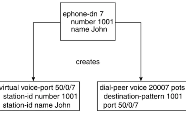
Figure 5-1 shows that ephone-dn 7 creates, or is associated with, virtual voice port 50/0/7 and a plain old telephone service (POTS) dial peer that references virtual voice port 50/0/7. The dial peer contains the voice port’s phone number. It is used for call-routing purposes for incoming calls. The virtual voice port contains the station ID that sets the caller ID properties (name and number) for the ephone-dn (used for outgoing calls).
Figure 5-1 Ephone-dn Components: Voice Port and Dial Peer
The terms dial peer and voice port are inherited from the Cisco IOS router voice infrastructure functions that have historically been used for applications such as VoIP gateways in toll-bypass networks (using protocols such as H.323, Session Initiation Protocol [SIP], and Media Gateway Control Protocol [MGCP]). In the router voice gateway context, a voice port typically refers to an interface that connects to the Public Switched Telephone Network (PSTN) (or PBX), but it also includes interfaces that directly connect to analog telephones. The behavior and usage of a virtual voice port is similar in many ways to a physical voice port used to connect to an analog telephone (specifically, a Foreign Exchange Station [FXS]). As a result of this similarity, you will see virtual voice ports called eFXS voice ports. In this terminology, the term eFXS means ephone-dn virtual FXS voice port.
creates
virtual voice-port 50/0/7 station-id number 1001 station-id name John
dial-peer voice 20007 pots destination-pattern 1001 port 50/0/7
ephone-dn 7 number 1001 name John
You can configure a virtual voice port to have one or two subchannels. Each subchannel can accept a single voice call. This arrangement is similar to the two bearer channels present on an ISDN BRI voice port. An ephone-dn that is configured in dual-line mode creates a virtual voice port that can handle two simultaneous calls. The primary use of the dual-line option is to provide a simple way to handle features such as call waiting. The dual-line option also provides a way to support the second call instance required by features, such as third-party conferencing and call transfer with consultation.
When you select the dual-line option, the Cisco IP phone provides a rocker button or (blue) navigation bar that is used as a scroll key to select between two call instances presented on the IP phone display. For example, in the case of call waiting, the phone display shows you the active (connected) call and the waiting (ringing) call. You can press the hold softkey to place the active call on hold, use the navigation bar to scroll the IP phone display, and then select the answer softkey for the waiting call.
Alternatively, call waiting can be supported simply by using an IP phone that has two (or more) physical line buttons. In this case, you configure each button with a separate phone line instance (ephone-dn). Instead of configuring a single ephone-dn in dual-line mode, you configure two ephone-dns with the same phone number using the default ephone-dn single-line mode (and the no huntstop option, which you’ll learn more about later, in the section “Cisco IOS Voice Dial Peer Hunting”). This provides a simpler and more traditional multiline user interface. You perform navigation between two simultaneous calls by simply pressing one of the line buttons to select the desired call. The previously active call is automatically placed on hold. This mode of operation is often called one button, one call.
The most basic elements of the Cisco CME configuration are the ephone and ephone-dn. You bind the ephone-dn elements you have created to the configured ephone entries using the button command within the ephone command submode. Example 5-1 shows a very simple example.
Example 5-1 shows a single IP phone (ephone 7) that is uniquely identified by its Ethernet MAC address (000d.aa45.3f6e). You can find the Ethernet MAC address on a sticker on the underside of your Cisco IP phone or from the phone’s shipping carton label. In many cases, the MAC address can be autodiscovered after the phone is plugged into your Cisco CME router’s LAN network. Example 5-1 also shows a dual-line ephone directory number (ephone-dn 4). This ephone-dn has telephone extension number 1001. Ephone-dn 4 is then associated or bound to the first line button of ephone 7 using the button command (button 1:4).
Example 5-1 Simple Ephone-dn Configuration router#show running-config
ephone-dn 4 dual-line number 1001 ephone 7
mac-address 000d.aa45.3f6e button 1:4
Example 5-2 shows a slightly expanded view of the CLI configuration in Example 5-1.
The configuration shown in Example 5-2 is all that’s needed to register your first IP phone provisioned with a single line button and to produce dial tone when you lift the handset. The only assumptions made here are that the phone is a Cisco 7960 IP Phone, that the phone firmware desired is the file P00303020214.bin, and that the firmware file is loaded into the router’s Flash memory.
The tftp-server, ip dhcp pool, and interface FastEthernet 0/1 commands shown are standard Cisco IOS CLI router commands that are outside the scope of this book, but you are most likely familiar with their basic function in the IP world. These commands are included just to provide a context for the Cisco CME-specific commands ephone, ephone-dn, and telephony-service. Cisco CME also has a telephony-service setup command that you can use to bring up a set of phones and provide basic service. This command includes automatic creation of the Dynamic Host Configuration Protocol (DHCP) pool CLI entry if you need it.
Example 5-2 Expanded Ephone-dn Configuration router#show running-config
tftp-server flash:P00303020214.bin ip dhcp pool cme network 192.168.0.0 255.255.255.0 default-router 192.168.0.1 option 150 ip 192.168.0.1 interface FastEthernet0/1 ip address 192.168.0.1 255.255.255.0 duplex auto speed auto telephony-service ip source-address 192.168.0.1 load 7960-7940 P00303020214 max-ephones 24 max-dn 24 create cnf-files ephone-dn 4 dual-line number 1001 ephone 7 mac-address 000d.aa45.3f6e button 1:4
Using a PBX Versus a Key System
The Cisco CME product addresses phone systems in the roughly 1-to-240-phone marketplace. This product spans the range from a small, independent, four-person professional services office (perhaps running on a Cisco 2801 router) to a mid-sized company to a large branch office of a multinational enterprise (running on a Cisco 3845 router). This marketplace has traditionally been addressed by a range of simple Key Systems (with perhaps two PSTN trunk lines and four extensions) to hybrid and small PBX systems (with multiple T1 Primary Rate Interface [PRI] digital PSTN interface trunks). Within this market space, the phone user interface expectations include simple one-extension per-phone configurations (usually with call waiting) to direct PSTN trunk appearance presence on all phones (any phone can answer any PSTN call). The next sections describe typical deployments for PBX systems and Key Systems.
PBX Usage: One Phone Line and One Phone
In a typical PBX-like deployment, you expect to see digital PSTN trunk lines, with direct inward dial (DID) for direct access to individual phone extensions and one or more
receptionists. The receptionist answers calls to the company’s primary public phone number and transfers these calls to the individual phone users. Each phone user has his or her own private extension number (and probably also a personal voice mailbox to handle busy or unanswered calls). In this arrangement, each IP phone normally has only a single phone number associated with it. You saw a sample configuration for the one-phone-to-one-extension case in Example 5-1.
You are likely to see a few exceptions to the one-phone-to-one-extension rule, such as in the case of a company executive who has an assistant. In this case, the assistant’s phone usually has two extension numbers—one shared with the executive (to allow the assistant to answer the executive’s calls) and one personal extension for calls intended for the assistant. This configuration is shown in Example 5-3.
Example 5-3 Two Extension Numbers Per Phone router#show running-config
ephone-dn 4 dual-line number 1001 name Boss ephone-dn 5 dual-line number 1002 name Assistant ephone 7 mac-address 000d.aa45.3f6e button 1:4 ephone 8 mac-address 000d.bb46.2e5a button 1:5 2:4
In Example 5-3, ephone 7 is the executive’s phone, with extension 1001 on line button 1. Ephone 8 is the assistant’s phone, with the assistant’s personal extension 1002 on button 1 and the executive’s extension 1001 shared on button 2. When a call arrives for 1001, both phones ring, and either phone can answer the call. When a call arrives for 1002, only the assistant’s phone rings. When the executive is using extension 1001, the assistant’s phone is unable to access the line. However, the display on the IP phone indicates that that line is in use so that the assistant knows that the executive is busy with a call.
Key System: One Phone Line and Many Phones
In the typical PBX environment described in the preceding section, an analysis of call traffic often shows that there are more internal extension-to-extension calls than external PSTN-to-extension calls. A result of this is the need for the one-person-to-one-phone-number configuration.
In a small four-person office, extension-to-extension calls may be nonexistent. It’s often easier to walk over and speak to a coworker than it is to phone him or her. In this environment, calls are predominantly PSTN-to-extension. Furthermore, incoming PSTN calls are the lifeblood of the small company, because each call can potentially be from a customer.
In this environment, often there is no need for personal extension numbers. What is important in this case is that somebody always promptly answers the incoming PSTN calls. A small four-person company, however, often cannot afford to hire a dedicated telephone receptionist. Example 5-4 gives a sample configuration for this type of environment.
Example 5-4 PSTN Lines on All Phones router#show running-config
ephone-dn 1 number 4085550101 no huntstop preference 0 ephone-dn 2 number 4085550101 preference 1 ephone 1 mac-address 000d.aa45.3f6e button 1:1 2:2 ephone 2 mac-address 000d.bb46.2e5a button 1:1 2:2 ephone 3 mac-address 000d.cc47.1d49 button 1:1 2:2 ephone 4 mac-address 000d.dd48.0c38 button 1:1 2:2
In Example 5-4, you see that ephone-dn 1 and ephone-dn 2 both have the same phone number. The phone number configured is the small company’s (fictitious) public PSTN phone number. This is the number that is displayed on the IP phones and also the PSTN number that customers dial to reach the company. You can configure the Cisco CME router’s PSTN interface to direct incoming PSTN calls to the first ephone-dn (for example, connection plar opx configured on an Foreign Exchange Office [FXO] port connected to the PSTN). If ephone-dn 1 is busy, calls automatically roll over to ephone-dn 2. To make this happen, you configure the ephone-dn with the same number, and then set explicit preference values to indicate the order for selection between the ephone-dns. The lower-preference 0 value attached to ephone-dn 1 indicates that ephone-dn 1 should be selected first. Also note that the no huntstop command gives the Cisco CME system permission to try to find an alternative destination for the incoming call if the first ephone-dn is busy. (You’ll read more about huntstop in the section “Cisco IOS Voice Dial Peer Hunting.”)
Note how easy it is to expand this basic two-by-four configuration to include more PSTN trunks and more IP phones. There is no specific limit on how many IP phones can share a single IP phone line. There is a limit on how many phone lines can be directly assigned to each IP phone. This limit is set by the number of available line buttons on the IP phone. For example, a Cisco 7960 IP Phone has six buttons, so you cannot directly assign more than six PSTN lines using the simple configuration method shown in Example 5-4. However, you can attach up to 60 lines to a 7960 IP Phone using a configuration option called overlay-dn. (You’ll read more about this in the section “Using Overlay-dn.”)
You can see from the examples that the simple binding arrangement between IP phone and IP phone lines creates a significant amount of flexibility. This allows the Cisco CME to support multiple styles of phone usage to meet different end-customer expectations. The PBX and Key System configuration styles are not mutually exclusive. You can combine configuration styles by simply adjusting the IP phone-to-IP phone line bindings as needed.
The one phone line and many phones configuration model applies much more broadly than just the four-person Key System example given here. Even within a larger company’s phone system, there are cases in which the one phone line and many phones model is appropriate. One example is for a company loading dock, where you might have several hundred square feet of loading/unloading storage space in a shipping and receiving department. In this situation, you may find it desirable to place multiple phones so that they are spread out across a wide physical area. In addition, any phone can be used to place and receive calls on the same line.
Implementing Shared Lines and Hunt Groups
Although it is widely used, the term hunt group seems to mean different things to different people and in different contexts. It’s a general term that covers the distribution of calls among a group of phones. In this chapter, the term call coverage refers to the general concept of call distribution across phones. This helps avoid confusion with the Cisco CME CLI command ephone-hunt. The ephone-hunt command is used to configure a specific kind of call coverage that involves sequential selection among a group of selected phone lines.
Many other types of call coverage are addressed with other commands, combinations of commands, and configurations. Examples include the use of shared lines, overlay-dn, call forwarding, secondary ephone-dn numbers, and combinations of these.
This section describes a number of different types of call coverage:
•
Simple sequential ringing of a selected set of phone lines•
Ringing of multiple phone lines at the same time, referred to here as parallel hunting•
Call forwarding from one line to another using call forward on busy or no-answer•
Combination sequences that involve sequential ringing of multiple phone lines, referred to here as sequential parallel huntingNotice that all these refer to ringing phone lines, not phones. Calls are sequenced through an ordered set of phone lines. Which phones ring depends on the binding of the lines to the phones. Each line can be bound to multiple phones.
The following sections discuss several types of call coverage.
Cisco IOS Voice Dial Peer Hunting
A good place to start a discussion of call coverage for Cisco CME is to look at the voice dial peer hunting mechanism that is a standard component of the Cisco IOS voice infrastructure. Dial peers have a very large number of configuration options. The most basic options are related to matching a telephone number and directing the call to a specific voice port or VoIP destination. More advanced options relate to number manipulation (using translation rules or translation profiles), application selection (including custom TCL scripts), protocol options (such as fax relay and dual-tone multifrequency [DTMF] relay), voice codec selection, and caller ID manipulation and restriction.
Some dial peer operations relate to selecting a dial peer associated with the call’s originator (incoming dial peer matching) and selecting a dial peer associated with the call destination (outgoing dial peer matching). Multiple parameters can affect the selection of the incoming and outgoing dial peers, but the primary matching criteria are the called and calling party numbers. Describing all the dial peer options in detail is outside the scope of this book; however, numerous books deal with this subject in more depth, including the following:
•
Deploying Cisco Voice over IP Solutions by Jonathan Davidson (Cisco Press, 2001).•
Cisco Voice over Frame Relay, ATM, and IP, edited by Steve McQuerry, Kelly McGrew, and Stephen Foy (Cisco Press, 2001).This section provides a simplified overview of dial peers to provide a basic understanding of some of the options that apply to call coverage—specifically, dial peer hunting. Example 5-5 shows two basic dial peers.
The first dial peer (dial peer 100) is a POTS dial peer. This type of dial peer is used to reference a local telephony voice port connected to the router.
The second dial peer (dial peer 200) is a VoIP dial peer used to reference a remote telephony device accessed via IP, usually across a WAN data link.
Both dial peers have a destination-pattern parameter. This associates a telephone number or range of telephone numbers with the dial peer. In the VoIP dial peer, you can see that the destination pattern contains the wildcard character “.” (to match any digit). In this example, the destination-pattern 20.. command matches telephone numbers in the range 2000 to 2099. Both dial peers associate a destination device with the phone number selected by the destination pattern. In the POTS dial peer case, the destination is a physical voice port on the router designated as port 1/0/0. Your router’s exact port numbering may vary by router type and voice interface type, but the basic numbering structure is slot/card/port.
In the VoIP dial peer case, the destination is an IP address, as indicated by the session target ipv4:10.0.4.2 parameter.
In Example 5-5, you can see how a dial peer is used to associate a telephone number (or range) with a destination, either a voice port or an IP address.
The dial peer hunting function comes into play when you create two or more dial peers that match the same telephone number but reference different destination devices. You can set many parameters to adjust the order in which matching dial peers are selected. The default behavior is called longest match. For longest match, the dial peer that most exactly matches the telephone number is preferred. A longest match selects the destination pattern that matches the desired number using the fewest “.” wildcard characters. The best kind of longest match is an exact match, where no wildcards are used and the destination pattern and telephone number match literally and exactly. This is often the case with POTS dial peers, where you assign a specific phone number to a specific port.
Example 5-5 Two Basic Dial Peers
router#show running-config
dial-peer voice 100 pots destination-pattern 1001 port 1/0/0
dial-peer voice 200 voip destination-pattern 20.. session target ipv4:10.0.4.2
Example 5-6 shows a dial peer configuration that illustrates some of the matching capabilities.
In Example 5-6, two POTS dial peers associate the phone numbers 2001 and 2007 to (local) voice ports 1/0/0 and 1/0/1. All other numbers in the 2000 to 2099 range are associated with the VoIP dial peer and are resolved somewhere in the VoIP space. This configuration provides a simplified way of indicating that the numbers 2001 and 2007 are local numbers. The remaining numbers in the range 2000 to 2099—specifically, 2002 to 2006 and 2008 to 2099—are remote and can be accessed via VoIP.
As a result of the longest-match rule, a call to 2001 selects POTS dial peer voice 101 in preference to VoIP dial peer 200. This is because the destination pattern for dial peer 101 has an exact match to the called number 2001, whereas VoIP dial peer 200 uses “.” wildcard digits to match 2001.
Example 5-7 shows a more complex configuration.
In Example 5-7, you can see that the two POTS dial peers now both have the same number. Because both dial peers provide an exact match to the number 2001, the longest-match criteria cannot distinguish between them. You also see that the dial peers now have an extra parameter,
Example 5-6 Simple Dial Peers
router#show running-config
dial-peer voice 101 pots destination-pattern 2001 port 1/0/0
dial-peer voice 102 pots destination-pattern 2007 port 1/0/1
dial-peer voice 200 voip destination-pattern 20.. session target ipv4:10.0.4.2
Example 5-7 More Complex Dial Peers router#show running-config
dial-peer voice 101 pots destination-pattern 2001 preference 1
port 1/0/0
dial-peer voice 102 pots destination-pattern 2001 preference 2
port 1/0/1
dial-peer voice 200 voip destination-pattern 20.. session target ipv4:10.0.4.2
preference. The preference command is used to define a specific preference order for selecting the dial peers. The call to 2001 goes to the dial peer with the lowest preference value. The default preference value is 0.
In Example 5-7, when an incoming call to 2001 arrives, it first goes to POTS dial peer 101 with preference 1. Only if the port 1/0/0 associated with this dial peer is busy does the dial peer matching process hunt to the second dial peer 102 (preference 2). This provides the first basic mode of call coverage hunting: dial peer hunt on busy.
You may notice that there is a potential problem with the dial peer hunt-on-busy arrangement in this example: What if the second port is also busy? If ports 1/0/0 and 1/0/1 are both busy, the dial peer hunting mechanism takes the call to the next best available match. The next best match in this example is the VoIP dial peer 200. This dial peer matches the 2001 number, because it has a wildcard-based match range that spans the entire range 2000 to 2099. This range includes the number 2001.
In most cases, you do not want the call to hunt on busy into the VoIP dial peer, because (in this example) there is no resolution for the number 2001 in the VoIP space. If a call to 2001 gets routed to the VoIP destination, the call will fail with a cause code (returned by the remote VoIP system) indicating that the number 2001 does not exist. This condition returns a fast-busy tone (number not in service) indication to the caller. This is not the correct behavior. What is needed is to return a simple user busy tone indication to the caller.
You can solve this problem by adding the dial peer option huntstop, as shown in Example 5-8.
The huntstop command option tells the dial peer hunting mechanism not to try to find any further dial peer matches. Instead, the dial peer hunting stops at the dial peer containing the huntstop command. If no available voice port is found, it returns a busy tone to the caller.
Example 5-8 Huntstop in a Dial Peer router#show running-config
dial-peer voice 101 pots destination-pattern 2001 preference 1
port 1/0/0
dial-peer voice 102 pots destination-pattern 2001 preference 2
huntstop port 1/0/1
dial-peer voice 200 voip destination-pattern 20.. session target ipv4:10.0.4.2
Example 5-9 shows another variation using dial peers to manage call coverage.
In Example 5-9, port 1/0/1 can be accessed by dialing 2001 or 2007. A call to 2001 first tries port 1/0/0. If this port is busy, it hunts to port 1/0/1. A call to 2007 goes directly to port 1/0/1. Note that the default for the huntstop parameter under dial peer is for huntstop to be disabled. As you will see later (in the section “Cisco IOS Voice Dial Peer Hunting”), the default for huntstop when applied to the ephone-dn configuration is for huntstop to be enabled.
Ephone-dn Dial Peers and Voice Ports
The preceding section provided an overview of dial peers as used by the generic Cisco IOS voice infrastructure software. This section shows how Cisco CME uses dial peers to enable routing of calls to IP phones. The Cisco CME CLI configuration of IP phones and IP phone lines does not directly include dial peers or (virtual) voice ports. Instead, the dial peer and virtual voice port resources used by Cisco CME are hidden inside the ephone-dn command. This simplifies the configuration steps needed to create an IP phone line. It avoids the manual process of creating POTS dial peers to bind phone numbers to virtual voice ports.
Here is the original ephone-dn command from the beginning of this chapter, modified with a user name added and a specific dial peer preference included:
ephone-dn 4 number 1001 name John Smith preference 1
Example 5-9 Dial Peer Variation
router#show running-config
dial-peer voice 101 pots destination-pattern 2001 preference 1
port 1/0/0
dial-peer voice 102 pots destination-pattern 2001 preference 2
huntstop port 1/0/1
dial-peer voice 102 pots destination-pattern 2007 huntstop
This ephone-dn command generates the configuration subelements shown in Example 5-10.
The ephone-dn command is more compact and saves you from entering some information twice, such as the number 1001. The station-id commands (under the voice-port command) set the caller ID properties (name and number) for the IP phone line. This establishes the calling party name and number for calls originated by the ephone-dn. Note that the dial peer destination pattern by itself is not a good way to set the caller ID information. This is because in the general case, you can have multiple POTS dial peers that reference the same voice port. Because each dial peer can specify a different destination pattern phone number for the voice port, you can see that attempting to imply the caller ID calling party number from the dial peer creates ambiguity. With multiple dial peers for the same voice port, determining which dial peer to choose to represent the calling party number is difficult. There are specific rules for incoming dial peer selection that select the calling party number from the dial peers, but these are outside the scope of this chapter. The dial peer destination pattern is used as the calling party number for calls from the voice port only if the station-id command is omitted from the voice port configuration. As you can see, the ephone-dn configuration takes care of this detail for you. Note the presence of the huntstop command in the generated dial peer in Example 5-10. This is discussed in the section “Cisco IOS Voice Dial Peer Hunting.”
Also note the (virtual) voice port numbering 50/0/4. The numbering convention varies by router type, but it’s typically slot/card/port. The value 50 was arbitrarily chosen as the virtual “slot” number for the virtual voice ports just to avoid contention with the routers’ physical network module slots. Currently, no routers (that support Cisco CME) have 50 physical slots, so there’s no confusion with physical hardware slot numbers. The middle card number value is always 0. The port number, 4 in this example, matches the ephone-dn tag value (as in ephone-dn 4). The dial peer tag numbering (20004) is not significant, but it usually has some correlation to the ephone-dn tag number, which is 4 in this example.
The only place that the virtual voice port port number is significant is in the binding of the ephone-dn dial peer to the virtual voice port. In most cases, you never need to be aware of the virtual voice port port numbers in your Cisco CME system.
If you execute the IOS command show running-config, you see only the ephone-dn commands you have entered, not the dial peer and virtual voice port commands. This is because the
Example 5-10 Ephone-dn Subelements router#show running-config
dial-peer voice 20004 pots destination-pattern 1001 preference 1 huntstop port 50/0/4 voice-port 50/0/4 station-id number 1001 station-id name John Smith
ephone-dn command automatically manages these subcommands for you, and there is no need for these to take up space in the router configuration. However, you can see the ephone-dn generated dial peers and virtual voice ports using the Cisco IOS commands show dial-peer summary and show voice-port summary.
The important point for you to understand here is that the dial peer and voice port configurations created by the ephone-dn do exist in the router configuration, even though they are not included in the output of show running-config. This point helps you understand how the Cisco CME configuration interacts with any general Cisco IOS voice infrastructure configuration that is included in your router, as well as for troubleshooting Cisco CME (covered in Part IV, “Maintenance and Troubleshooting”).
Ephone-dn Secondary Number
The ephone-dn secondary number allows you to associate a second phone number with the same IP phone line. You can use this to create a simple hunt-on-busy configuration. This allows you to use the dial peer hunt-on-busy mechanism to make a call roll over from one line to another, even when the lines have different primary phone numbers. Example 5-11 shows an example.
This ephone-dn command generates the configuration subelements shown in Example 5-12.
Example 5-11 Ephone-dn Secondary Number router#show running-config
ephone-dn 4
number 1001 secondary 1007 name John Smith
preference 1 secondary 2
Example 5-12 Ephone-dn Subelements router#show running-config
dial-peer voice 20004 pots destination-pattern 1001 preference 1
huntstop port 50/0/4
dial-peer voice 30004 pots destination-pattern 1007 preference 2 huntstop port 50/0/4 voice-port 50/0/4 station-id number 1001 station-id name John Smith
If you compare this with the earlier Example 5-7, you can begin to see how the ephone-dn command can leverage the IOS voice infrastructure dial peer hunting mechanism to provide simple call coverage. The configuration in this example causes incoming calls to both 1001 and 1007 to be routed to the IP phone line created by the ephone-dn 4 command, provided that no other dial peer elements in the system preempt the call routing path with a destination pattern match that has a lower numeric preference value.
Example 5-13 shows how you can use the ephone-dn secondary number to create dial peers that provide a simple form of call coverage.
Example 5-14 shows the dial peers and voice port configurations that these commands generate.
Example 5-13 Ephone-dn Secondary Number router#show running-config
ephone-dn 4
number 1001 secondary 1007 name John Smith
no huntstop
preference 1 secondary 2 ephone-dn 5
number 1007 secondary 1001 name Jane Smith
no huntstop
preference 1 secondary 2
Example 5-14 Ephone-dn Subelements router#show running-config
dial-peer voice 20004 pots destination-pattern 1001 preference 1
no huntstop port 50/0/4
dial-peer voice 30004 pots destination-pattern 1007 preference 2
no huntstop port 50/0/4
dial-peer voice 20005 pots destination-pattern 1007 preference 1
no huntstop port 50/0/5
dial-peer voice 30005 pots destination-pattern 1001 preference 2
With the configuration in Example 5-14, you can see that an incoming call to 1001 first goes to dial peer 20004 (preference 1) and tries virtual voice port 50/0/4 (for ephone-dn 4). If this port is busy, the call hunts on busy from dial peer 20004 to dial peer 30005 (preference 2) and tries virtual voice port 50/0/5 (for ephone-dn 5). In a similar manner, you can see that a call to 1007 first goes to ephone-dn 5 and then hunts to ephone-dn 4.
The dial peer hunting mechanism works only for hunt on busy. It does not provide hunting on no-answer timeout.
Note the use of the no huntstop command under ephone-dn. Without having this command present, the dial peer hunting stops at the first dial peer it reaches. The literal command text for no huntstop does not actually appear in the dial peers if you examine them using the show dial-peer Cisco IOS commands. This is because no huntstop is the default configuration for a dial peer, and default configuration items normally are not included in the IOS show running-config command display output. The no huntstop text is included in the preceding dial peer examples for clarity only. The no huntstop command is required under ephone-dn. This is needed to turn off the default ephone-dn configuration, which has huntstop enabled by default.
Using Call Forwarding for Call Coverage
In the examples of dial peer matching, you saw how calls can be distributed over a number of ephone-dn IP phone lines without changing the called number for the call. You can also use call forwarding to provide simple forms of call coverage. Cisco CME supports call forwarding for busy, no-answer, and unconditional (or call-forward all). When you use call forwarding to provide call coverage, the called number for the call changes. This can affect what is displayed on the IP phone receiving the forwarded call and entry into voice mail. Example 5-15 shows an example of a call forwarding configuration.
port 50/0/4 voice-port 50/0/4
station-id number 1001 station-id name John Smith voice-port 50/0/5
station-id number 1007 station-id name Jane Smith
Example 5-15 Call Forwarding
router#show running-config
ephone-dn 4 dual-line number 1001 name John Smith call-forward busy 1007
call-forward noan 1007 timeout 20 Example 5-14 Ephone-dn Subelements (Continued)
In Example 5-15, you can see that John and Jane’s phones are set to call forward on busy or no-answer (noan) to each other’s phone. There’s an issue with this configuration, because it potentially creates an infinite forwarding loop. If neither phone is answered, the call is repeatedly forwarded back and forth between the two phones until the caller hangs up. You can limit the number of times the call forwarding loop is traversed by setting the max-redirect command under telephony-services. The max-redirect command has a range of 5 to 20 and a default value of five. This is a global command and limits call forwarding system-wide.
Using Shared Lines for Call Coverage
The previous examples showed you how to use the Cisco IOS voice infrastructure dial peer hunting mechanism to control the routing distribution of incoming calls across more than one line (virtual voice port). These examples assume that each different IP phone line is associated with a different IP phone. In this section, you learn how to distribute calls between multiple phones using only a single IP phone line. Example 5-16 uses a simple shared-line configuration to move a call between phones by dynamically moving the line ownership between phones instead of moving the call between lines.
ephone-dn 5 dual-line number 1007 name Jane Smith call-forward busy 1001
call-forward noan 1001 timeout 20
Example 5-16 Shared-Line Configuration router#show running-config
ephone-dn 1 number 1001 name John Smith ephone-dn 2 number 1002 name Jane Smith ephone-dn 3 number 5001 preference 1 no huntstop name SalesLine1 ephone-dn 4 number 5001 preference 2 name SalesLine2 Example 5-15 Call Forwarding (Continued)
Example 5-16 shows two IP phones. Ephone 12 belongs to John Smith and has John’s personal phone line on button 1 (button 1:1). Ephone 15 belongs to Jane Smith and has Jane’s personal phone line on button 1 (button 1:2). Note that the personal line on button 1 is the default line that’s selected for outgoing calls when the phone’s handset is taken off-hook (you can change this with the auto-line command).
Both phones have ephone-dns 3 and 4 associated with buttons 2 and 3. Ephone-dns 3 and 4 both have the same telephone number—5001. The ephone-dns are set up so that the first call to the sales line goes to ephone-dn 3. If ephone-dn 3 is busy, a second incoming call will dial peer hunt on busy to ephone-dn 4.
Both ephone-dns 3 and 4 are present on both IP phones so that calls to either ephone-dn ring both IP phones. John and Jane can see at a glance which lines are in use.
Either John or Jane’s phone can answer the first incoming call to 5001 SalesLine1. The second call rolls over to 5001 SalesLine2 and also goes to both phones. The phone that is busy with the first call sees the second call as call waiting (and hears a call waiting beep, which can be disabled). The other phone rings.
Furthermore, John can place his call on hold. This makes the call fully visible to Jane because it is on a shared line, and she can pick up the call simply by pressing the corresponding line button on her phone. Note that in this case of shared line pickup on hold, the call does not change lines. Rather, the active ownership of the line moves between the phones. The call stays on the same line throughout the call.
Using Overlay-dn
The preceding section described a simple two-by-two arrangement in which two phones share two IP phone lines. This type of arrangement can be expanded to, say, four lines shared by eight phones. However, there is a limit on how far you can go with this arrangement. A Cisco 7960 IP Phone has only six line buttons, so the maximum number of lines that it can directly share is six. If you also consider that the line buttons on a Cisco 7960 IP Phone can also be configured for speed dial or other uses, such as personal extensions and intercoms, you can see that it’s fairly easy to run out of buttons.
The Cisco CME overlay-dn configuration provides a way around the physical button limit for many cases. ephone 12 mac-address 000d.1234.0efc button 1:1 2:3 3:4 ephone 15 mac-address 000d.5678.0dcf button 1:2 2:3 3:4
Example 5-17 shows an alternative arrangement for John and Jane’s phones that provides a simple example of an overlay-dn configuration.
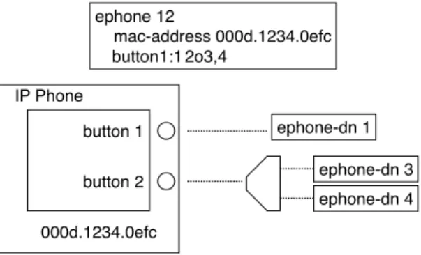
The only thing that is different about this configuration relative to Example 5-16 is the button command button 1:1 2o3,4.
To configure a button for overlay use, you simply replace the colon button:dn separator with the letter o, for overlay. Following the o separator, you provide a list of two to ten ephone-dn tag numbers. You must have at least two ephone-dns in the overlay set to use the o separator. You can see that this configuration uses only two buttons instead of the three buttons used originally. This leaves the additional buttons available for use as speed dial buttons, for example. Alternatively, you can use a lower-cost IP phone, such as the Cisco 7940 IP Phone, which has only two buttons instead of the six buttons of a Cisco 7960 IP Phone.
An overlay-dn arrangement works as a multiplexor. This works in a similar way to an old-fashioned printer-sharer device that allows multiple PCs to drive a shared printer.
When an incoming call arrives on one of the ephone-dns in the IP phone’s button overlay set, the ephone-dn with the ringing call is multiplexed onto the appropriate button. At any time, only one ephone-dn in the overlay set is actively bound to the IP phone. When all ephone-dns in the overlay set are idle, the first ephone-dn in the set is the one that is actively bound to the phone. You can see this multiplexing activity using the show ephone command (examples of this are provided later in this book).
Example 5-17 Overlay-dns
router#show running-config
ephone-dn 1 number 1001 name John Smith ephone-dn 2 number 1002 name Jane Smith ephone-dn 3 number 5001 preference 1 no huntstop name SalesLine1 ephone-dn 4 number 5001 preference 2 name SalesLine2 ephone 12 mac-address 000d.1234.0efc button 1:1 2o3,4 ephone 15 mac-address 000d.5678.0dcf button 1:2 2o3,4
The ephone-dn is multiplexed into the active slot for the button when it needs to be used, as shown in Figure 5-2.
Figure 5-2 Overlay-dn Multiplexes Multiple Lines to a Single Button
When an outgoing call is attempted on a button that is configured for an overlay, the first available idle ephone-dn in the overlay set is selected based on the left-to-right order of the ephone-dn tags used in the phone’s button overlay command.
The one drawback of the overlay-dn configuration is that you cannot perform the shared-line pickup on hold operation described in Example 5-16. Also, overlay-dn lines do not provide call waiting indication when multiple calls are present in the overlay set. This is because with ten lines mapped to a single button, the number of waiting calls can be rather large and generate too many interruptions.
When you use the overlay-dn configuration in a shared-line configuration (as in this example), it is recommended that you have at least as many lines in the overlay set as there are phones sharing. If there are more phones than lines in the shared-line overlay, when all ephone-dns are in use, you can get situations where there is no available ephone-dn to multiplex onto a phone. There is no specific harm in this situation, except the user confusion that may result when a user presses the line button and does not get dial tone (because no line is available).
An IP phone can have as many overlay sets as it has buttons. Each overlay set on each button on each IP phone can contain a unique set of ephone-dn tags. If you apply a ten-way overlay set to each of the six buttons on a 7960 IP Phone, 60 ephone-dns can be associated to the phone. You can use an overlay-dn to support multiple lines, even on a phone such as the Cisco 7912 IP Phone, which normally is considered a line phone. The key difference between a single-line phone with a six-way overlay and a six-button phone with one ephone-dn per button is in the ability to see and navigate between calls. With a six-way overlay onto a single-line phone, you can see the status of only one line at a time. You also have no direct choice over which of the six lines is being used. The overlay multiplex mechanism makes the choice for you. With a six-button phone, you can see all the calls at once, and select between them by pressing the line button for the call you want.
!!" # !! !! $ $
The section “Using Overlay to Overcome Phone Button Count Limits” has more information on using overlays.
Called Name Display for Overlay Extensions
In most cases, when you overlay multiple extensions onto a single button, the set of extensions included in the overlay set is usually closely related, so you often don’t need to distinguish between the individual extensions in an overlay set. But if you assign multiple unrelated extensions to the same phone button using an overlay, the phone user needs to know which extension is being called.
Cisco CME 3.2 introduced the called-name dialed number identification service (DNIS) to address this problem. This uses the command service dnis overlay (set under telephony-service). If this command is active, an incoming call on the (hidden) second through last members of the overlay set displays the extension name that is being called on the bottom line of the Cisco IP phone display. This name is set using the name command in the ephone-dn extension configuration. This allows the phone user to see at a glance which extension is ringing and allows the phone user to answer the call with a greeting appropriate to the specific extension. When the first (primary) extension in the overlay set is called, no name display appears, because the identity of the first extension line is implicitly indicated by the extension number display next to the phone line button itself.
Another thing to note about overlays is that if you put an overlay call on hold, the phone displays the extension number of the specific extension from the overlay set. This is useful if you want to perform a call on-hold extension pickup using the phone’s pickup softkey.
Called Name Display for Non-Overlay Extensions
If you want to see the called name in cases where you are not using an overlay, you can use the service dnis dir-lookup command (under telephony-service). This command is useful when you are taking calls from the PSTN using a digital PRI trunk configured to receive calls for a large block of numbers and where each number is associated with a separate person or company.
For example, consider a doctor’s answering service, where an agent may be taking messages for a group of 30 different doctors and where each doctor has a different answering service phone number for patients. In this simple example, assume that all the phone numbers are part of a specific block of numbers, say 555-0500 to 555-0529.
It’s easy to set up a single Cisco CME extension to accept these calls using the “.” wildcard character as part of the extension number:
ephone-dn 20 number 55505..
This takes care of routing the call to the right place, but it doesn’t tell you which specific number is being called. To display the called name (for example, Dr. Smith for calls to 555-0500 or Dr.
Jones for calls to 555-0501), you enable the service dnis dir-lookup command and configure the phone number-to-name associations that you want using the directory entry command as follows:
telephony-service
service dnis dir-lookup
directory entry 1 5550500 name Dr. Smith directory entry 2 5550501 name Dr. Jones
You can create a list of up to 100 directory entries to be used in this way. With this configuration, an incoming call to 0500 rings ephone-dn 20 and displays Dr. Smith, whereas a call to 555-0501 displays Dr. Jones. This allows the agent who answers the call to greet the caller with “Dr. Smith’s answering service” or “Dr. Jones’s answering service,” as appropriate.
The ephone-hunt Command
The ephone-hunt command gives you a simple way to configure a sequential call group based on a list of extension numbers. You can configure up to ten ephone-hunt groups in a Cisco CME system (as of CME 3.0). Each ephone-hunt group can contain a list of up to ten extension numbers. Note that you should make sure that the global max-redirect limit set for your system (under telephony-service) is higher than the maximum number of internal forwards needed by your hunt groups.
You can choose from three ephone-hunt modes:
•
Sequential mode—This gives a simple ordered list of extension numbers. Each extension number in the list is tried in turn, always starting from the beginning of the list. If the end of the list is reached without finding an available number, the call is forwarded to a number configured as a final destination.•
Peer mode—This gives a circular list of extension numbers. The starting point in the list for a new call is set by the last number tried for the preceding call. Because the list is circular, you have to set a parameter to limit how many times a call can be sequenced from one extension to the next. This value has to be less than the global call forwarding hop count limit set for the entire Cisco CME system by the max-redirect command. You have to do this to avoid an infinite hunting loop. You control it by setting the maximum number of hops for the call in the ephone-hunt command’s subcommands. As soon as the maximum number of hops has been reached, the call is forwarded to the number defined as the final destination for the hunt group.•
Longest idle—This also gives a circular list of extension numbers. The starting point in the list for a new call is set by the number that has been on-hook for the longest period of time. Again, because the list is circular, you have to set a parameter to limit how many times a call can be sequenced from one extension to the next. As soon as the maximum number of hops has been reached, the call is forwarded to the number defined as the final destination for the hunt group. The longest idle option was introduced in Cisco CME 3.2.Example 5-18 provides a configuration for these modes.
If you look at the two ephone-hunt commands in Example 5-18, you can see that some of the extension numbers are present in both ephone-hunt lists. This illustrates one of the advantages of ephone-hunt. In the previous examples, hunting to the IP phone ephone-dn lines is based on binding telephone numbers directly to the ephone-dns themselves. Because you can directly bind only two numbers per ephone-dn (the primary and secondary numbers), you are limited in how many simultaneous ways you can route calls to the ephone-dn.
In Example 5-13, you saw how both phones could be called using the numbers 1001 and 1007. This was done using the ephone-dn secondary number of the individual ephone-dns. You cannot add a third phone using this technique.
Example 5-17, which uses an overlay-dn, allows for greater expansion, but at the expense of consuming additional ephone-dns (at about 50 KB of memory per ephone-dn).
The other issue with using hunt numbers directly associated with the ephone-dns is that the call hunting path goes directly through each ephone-dn. This means that if you set any type of call forwarding on the ephone-dn (forward all, on busy, or no-answer), this forwarding affects the call hunt path too.
This is not true when you use the ephone-hunt command. You can set call forwarding on the individual ephone-dn without affecting the call hunt path defined by the ephone-hunt list. When you use the ephone-hunt command and enter a list of numbers, here’s what happens:
•
The system searches for all ephone-dn entries that have primary numbers that match the ephone-hunt list.•
For each ephone-dn that matches, the ephone-dn builds an additional dial peer. This dial peer has a number that’s derived from the ephone-hunt pilot number plus the relative position of the matched number in the ephone-hunt list. The dial peer also includes the virtual voice port number from the matching ephone-dn.Example 5-18 ephone-hunt Command router#show running-config
ephone-hunt 1 sequential pilot 5001 list 1001, 1003, 1007, 1008 final 6001 preference 1 timeout 15
ephone-hunt 2 peer (or longest-idle) pilot 5002 list 1002, 1003, 1008, 1009 final 6002 hops 3 preference 1 timeout 15
When you configure call forwarding under ephone-dn, the call forwarding information is inserted into the dial peers that are directly bound to the ephone-dn. The call forwarding information is not included in the dial peers created by the ephone-hunt command.
You also notice that the ephone-hunt command lets you set a preference value. As you might expect, this is a dial peer preference. The dial peer preference is inserted into the dial peer that is created by ephone-hunt to match the ephone-hunt pilot number.
For the ephone-hunt configuration examples shown, at least five dial peers are created. One dial peer is created for the pilot number. One dial peer is created for each ephone-dn that is found that matches one of the numbers in the list. If multiple ephone-dns match the individual numbers in the list, each of those ephone-dns causes the creation of an additional dial peer. Here is a description of what you see for ephone-hunt 1 in Example 5-18:
•
The pilot number creates a dial peer with destination pattern 5001. This dial peer has call forward all set to the first dial peer in the hunt list.•
The first member of the list creates a dial peer with destination pattern A5001A0001. This dial peer contains the virtual voice port number of the ephone-dn that has 1001 as its primary number. This dial peer has call-forward busy and call-forward no-answer set to the next ephone-hunt dial peer. The call-forward timeout value is set by the timeout subcommand under ephone-hunt.•
The second member of the list creates a dial peer with destination pattern A5001A0002. This dial peer contains the virtual voice port number of the ephone-dn that has 1003 as its primary number. This dial peer has call-forward busy and call-forward no-answer set to the next ephone-hunt dial peer.•
The third member of the list creates a dial peer with destination pattern A5001A0003. This dial peer contains the virtual voice port number of the ephone-dn that has 1007 as its primary number. This dial peer has call-forward busy and call-forward no-answer set to the next ephone-hunt dial peer.•
The fourth and final member of the list creates a dial peer with destination pattern A5001A0004. This dial peer contains the virtual voice port number of the ephone-dn that has 1008 as its primary number. This dial peer has call-forward busy and call-forward no-answer set to the number defined as the final destination for the ephone-hunt.The digit A in the destination pattern is the DTMF digit A from the extended set of DTMF digits A to D. The digits A to D are routable digits within the Cisco IOS voice infrastructure software and can be used just like the digits 0 to 9 and *. The digit # is often used as a dial digit string terminator.
You can view all the dial peers created by the ephone-hunt command using the Cisco IOS command show dial-peer voice summary. Example 5-19 shows the dial peers associated with ephone-hunt 1 in Example 5-18.
The SESS-TARGET column shows the virtual voice port numbers that correspond to ephone-dns 1, 3, 7, and 8.
Using Ephone-dn Dual Line
The several previous call coverage examples included ephone-dns configured in the default single-line mode. This helps keep the examples relatively simple. If you use ephone-dn dual-line mode, you should consider how you want to treat call waiting calls.
When you create an ephone-dn configured as dual line, you provide the ephone-dn with a virtual voice port that has two subchannels so that it can accept two simultaneous calls. This operates in a similar manner to an ISDN BRI voice port that has two bearer channels. By default, for a dual-line ephone-dn, when the first subchannel is busy with an active call, a second call is routed onto the second channel.
This behavior is usually not wanted in a hunt group. You normally want the second call to go to the next member of the hunt group instead of being present as a waiting call on the first member. If you configure the ephone-dn as a single line, you don’t need to worry about this behavior. In this case, no second channel exists, so there is no choice but for the second call to go to the next hunt group member.
To prevent the presentation of call waiting calls in a hunt group situation, you should use the command huntstop channel. This command can be used independently of, and in addition to, the plain huntstop command. The huntstop channel command prevents incoming calls from hunting on busy from the first virtual voice port channel to the second channel. It does not affect hunting between dial peers. It influences channel hunting only within the voice port. The huntstop channel command can be used in any dual-line ephone-dn. Its use is not restricted to ephone-hunt.
The effect of the huntstop channel command is to prevent incoming calls from reaching the second channel of a dual-line ephone-dn. This effectively reserves the second channel for outgoing calls from the ephone-dn. This can be used to guarantee the availability of the second
Example 5-19 Ephone-hunt 1 Dial Peers
router#show dial-peer voice summary
TAG TYPE ADMIN OPER DEST-PATTERN PREF SESS-TARGET 20051 pots up up 1001 0 50/0/1 20053 pots up up 1003 0 50/0/3 20057 pots up up 1007 0 50/0/7 20058 pots up up 1008 0 50/0/8 20069 pots up up A5001A000 1 50/0/1 20070 pots up up 5001 1 50/0/1 20071 pots up up A5001A001 1 50/0/3 20072 pots up up A5001A002 1 50/0/7 20073 pots up up A5001A003 1 50/0/8
channel to support the second call instance required for features such as three-party conference and call transfer with consultation.
If you use ephone-dn configured as dual line within a hunt group situation, it is recommended that you also use the huntstop channel command, as shown in Example 5-20.
Hunting Chains
Cisco CME provides a flexible set of mechanisms to support call coverage. These mechanisms are based on creating dial peers that are linked using hunt-on-busy arrangements and call forwarding.
The ephone-hunt command includes the option to set a final destination to forward calls to, when all hunt group members are busy. The number you forward to is itself resolved by another dial peer somewhere in the system. There is no restriction on the nature of the dial peer this number is linked to. The dial peer selection for the final number is based on the normal Cisco IOS voice infrastructure rules, taking into consideration criteria such as longest match and dial peer preference.
You can set the final destination of one ephone-hunt group to be the pilot number of a second ephone-hunt. The only restriction to consider is that the total number of times a call is forwarded cannot exceed the maximum set by the max-redirect command (under telephony-service). This has an allowed range of 5 to 20. You must count the internal forwarding hops included in each ephone-hunt when you figure the forwarding limit.
Also note that there is no restriction on the dn configuration matched by the ephone-hunt list. The ephone-dns matched to the ephone-ephone-hunt list can be part of more complex configurations. For example, you can use shared lines and overlay-dn as matches for the
Example 5-20 huntstop channel Command router#show running-config
ephone-dn 1 dual-line number 1001 huntstop channel ephone-dn 3 dual-line number 1003 huntstop channel ephone-dn 7 dual-line number 1007 huntstop channel ephone-dn 8 dual-line number 1008 huntstop channel ephone-hunt 1 sequential pilot 5001 list 1001, 1003, 1007, 1008 final 6001 preference 1 timeout 15
ephone-hunt list. This lets you create some very complex call coverage arrangements, including arrangements that perform sequential-parallel hunting, in which different groups of phones ring in a defined linear or circular sequence.
One final point here is that setting call-forward all for an ephone-dn that is part of a hunt group does not break the hunt group forwarding sequence. This is because the call-forward all is applied only to the ephone-dn’s main dial peer, not to the subsidiary dial peers that are generated by the ephone-hunt command. To temporarily remove a phone from a hunt group, you simply put the phone into Do-Not-Disturb mode (the Cisco CME 3.2 DND feature).
Immediate Diversion of Calls to Voice Mail
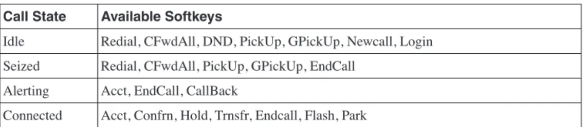
In earlier sections, you saw the use of the call-forward busy and call-forward noan (no answer) commands to control call forwarding of calls for busy and no-answer extensions. In many cases, the number the call is forwarded to is the pilot number for a voice mail system. Cisco CME 3.2 and later allows the person receiving a call to cause the incoming call to be forwarded immediately without having to wait for the no-answer timer to expire. (This is applicable only on Cisco IP phones that have softkeys.) When an incoming call is presented, the phone user sees two softkeys: answer and DND (Do Not Disturb). If the user’s phone has call-forward no-answer configured, pressing the DND softkey causes the incoming call to be forwarded immediately to the number configured for call-forward no-answer (typically the voice mail number).
If no call-forward no-answer is configured for the extension, pressing the DND key simply mutes the phone’s ringer until the call is cancelled (by the caller hanging up). The ringer mute DND action is temporary and applies only to the current call when used in the manner described. The phone can also be placed in a permanent muted ringer state by pressing the DND softkey while the phone is in the idle state. This allows the phone user to screen incoming calls, because the phone display is still active and shows the caller ID for incoming calls. If a phone user wants to avoid all incoming calls, you can use the cfwdall (call forward all) softkey to set up unconditional forwarding of incoming calls to voice mail (or another extension). In this case, there is no indication of incoming calls on the user’s phone.
Call Coverage Summary
This section has described a wide array of techniques for providing call coverage solutions. You can use the dial peer hunting mechanisms provided by the Cisco IOS voice infrastructure features. You can use call forwarding. You can use the ephone-hunt mechanism. You also have the option of using overlay-dn. You may combine several of these options to produce complex call coverage paths.
Creating an Intercom
Cisco CME supports single-button push-to-talk and push-to-respond intercom lines. You can create an intercom arrangement between any two (multiline) IP phones that support speakerphone operation. You can even operate an intercom across a VoIP connection using either SIP or H.323. Cisco CME’s intercom function is built using two functions:
•
Autodial at the initiating end of the intercom•
Autoanswer-with-mute at the receiving endTo create an intercom you assign a line button on each of the two phones to operate as an intercom line. Pressing the intercom line button selects the line and triggers the autodial function toward the second phone. The receiving phone receives the incoming intercom call on its intercom line. This line autoanswers the call and activates the phone in speakerphone mode and sounds a beep. It also forces the speakerphone to mute to protect the privacy of the intercom recipient. The audio path is open from the initiator to the receiver. To respond to the intercom, the recipient simply presses the mute button to unmute the audio path back to the originator.
The intercom Command
Example 5-21 shows a configuration of an intercom between two IP phones.
Example 5-21 shows two phones. John’s phone has button 1 as his primary extension line. Button 2 on John’s phone is an intercom line. This line is set to autodial Jane’s phone using the number 1111. The button is labeled “Jane” to show that pressing the button intercoms to Jane.
Example 5-21 Intercom Lines
router#show running-config
ephone-dn 1 dual-line number 1001 name John Smith ephone-dn 2 dual-line number 1002 name Jane Smith ephone-dn 3 number 1111
intercom 1112 label Jane ephone-dn 4
number 1112
intercom 1111 label John ephone 12 mac-address 000d.1234.0efc button 1:1 2:3 ephone 15 mac-address 000d.5678.0dcf button 1:2 2:4
NOTE The intercom lines are configured in the default single-line mode.
Jane’s phone is configured to match to John’s phone. Button 1 on Jane’s phone is her primary line. Button 2 is set to autodial John’s phone and shows the label “John” next to the button. The default configuration for an intercom line is that it autoanswers with mute for any incoming call. Autoanswer can be disabled if desired using the no-auto-answer command option.
Example 5-21 shows a fully symmetric two-way intercom arrangement. John can intercom to Jane, and Jane can intercom to John.
Individual phones may have more than one intercom. The maximum number of intercoms per phone is limited only by the number of available buttons. In general, using intercoms on single-line phones such as the Cisco 7910, 7905, and 7912 is not recommended. These phones do not have a built-in (hands-free) microphone and, therefore, cannot be unmuted without lifting the phone’s handset.
Many-to-One Intercom
In the previous example you saw that an intercom line autoanswers any incoming call. The incoming intercom does not perform any type of cross-check on the calling party to ensure that it matches the outgoing intercom destination. This arrangement lets you create a many-to-one intercom, which is useful when you have a single shared assistant working for multiple executives, as shown in Example 5-22.
Example 5-22 Shared-Line Intercom router#show running-config
ephone-dn 1 dual-line number 2101 name Executive1 ephone-dn 2 dual-line number 2102 name Executive2 ephone-dn 3 dual-line number 2103 name Executive3 ephone-dn 4 dual-line number 2201 name Assistant ephone-dn 5 number 1110
intercom 1110 label Intercom ephone-dn 6
number 1111
intercom 1110 label Intercom ephone-dn 7