Mobile & Sound Decoder Manual
Second Edition
Includes:
Digitrax Series 3, 4, 5 & 6
Mobile, Sound & Function Decoders
Digitrax, Inc.
2443 Transmitter Road
Panama City, Florida 32404
www.digitrax.com
LocoNet RDigitrax Manuals & Instructions are updated periodically. Please visit www.digitrax.com
For the latest version of all manuals & instructions. This manual was updated 04/15
C
T
C
omplete
rain
ontrol
Digitrax Mobile &
Sound Decoder Manual
Second Edition
Table of Contents R
1.0 Introduction ...
62.0 Digitrax Mobile and Sound Decoder Overview ...
62.1 Digitrax Decoder Part Numbering System ...7
3.0 Decoder Installation ...
93.1 Decoder Installation Basic Steps ...9
3.2 Choosing a Locomotive ...9
3.3 Choosing The “Right” Decoder ...10
3.3.1 The Digitrax On-Line Decoder Selector ...10
3.3.2 What Is Your Loco’s Stall Current? ...10
3.3.3 Which Decoder Will Fit? ...11
3.3.4 Decoder Interfaces for Installation ...12
3.3.4.1 Plug ‘N Play and Board Replacement Interfaces ...12
3.3.4.2 Digitrax 9 Pin HO & 8 Pin N Decoder Interfaces ....14
3.3.4.3 Installing Decoders with Wires ...14
3.3.5 Decoder Features-LocoMotion ...16
3.3.6 Decoder Functions-Lights, Sound, Etc. ...16
3.3.7 SoundFX Decoders ...17
3.4 Read the Instructions ...17
3.5 Plan the Installation ...17
3.6 Have the Proper Tools At Hand ...17
3.7 Testing Decoders Before Installation ...18
3.8 Locomotive Disassembly ...20
3.9 Electrically Isolating the Motor ...21
3.10 Installing Lighting Effects ...23
3.11 Installing Power Xtenders ...23
3.12 Final Decoder Test ...24
3.13 Avoiding Heat Problems with Installations ...24
4.0 General Decoder Troubleshooting ...
254.1 The decoder won’t respond ...25
4.2 The decoder runs for a while & then just stops ...26
4.3 Loco operation is jerky & erratic ...26
4.4 “Strange” locomotive light operation ...26
4.5 The locomotive won’t move at all ...26
4.6 Locomotive “buzzes” ...27
4.7 The Quarter Trick ...27
4.8 Are your LocoNet Cables built correctly? ...27
5.0 Decoder Programming ...
285.1 What are Configuration Variables (CVs)? ...28
5.2 Service Mode and Ops Mode Programming Methods ...28
5.3 Programming Modes ...28
5.4 DCC Outputs: Programming & Layout Operation ...29
5.5 Reading & Writing CVs ...29
6.0 CVs-Configuration Variables ...
307.0 Basic Decoder Setup CVs ...
347.1 Decoder Addresses ...34
7.1.1 Decoder 2 Digit Address: CV01 ...35
7.1.2 Decoder 4 Digit Address: CV17 & CV18 ...35
7.2 Configuration Register: CV29 ...36
7.2.1 Characteristics Controlled by CV29 ...36
7.2.2 Determining CV Value To Program Into CV29 ...37
8.0 LocoMotion CVs ...
408.1 Acceleration and Deceleration Rates ...40
8.1.1 Acceleration Rate: CV03 ...40
8.1.2 Deceleration Rate: CV04 ...40
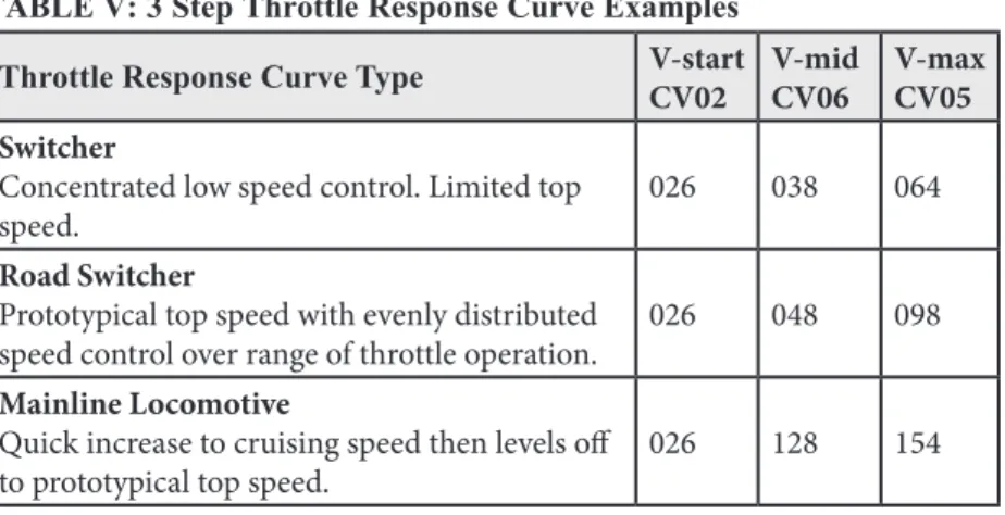
8.2 Throttle Response Curves & Loadable Speed Tables ....41
8.2.1 Simple 3 Step Speed Table ...42
8.2.2 V-Start: CV02 ...42
8.2.3 V-Max: CV05 ...42
8.2.4 V-Mid: CV06 ...42
8.2.5 Simple 3 Step Speed Table Examples ...43
8.3 High Res 28 Step Loadable Speed Tables CV65-95 ...43
8.4 CV54 Torque Compensation, Switching Speed & Decoder Lock Disable ...46
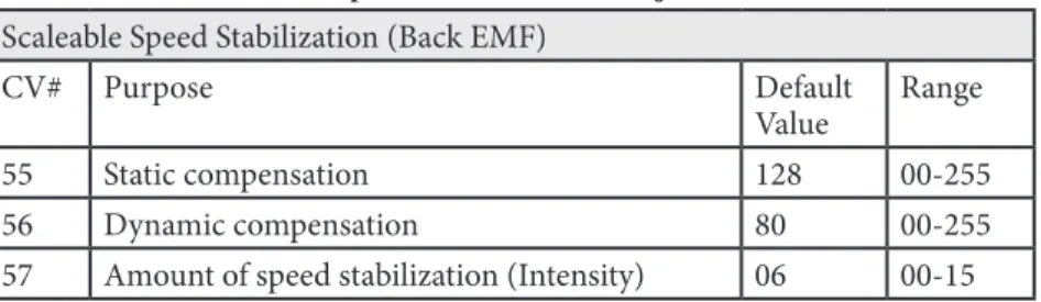
8.5 Scaleable Speed Stabilization (Back EMF) ...47
8.6 Advanced Consist Address CV19 ...50
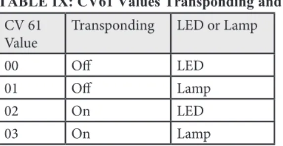
8.7 CV61 Transponding & LED/Lamp Algorithm Selector ....50
8.7.1 Transponding Feed Back From Decoders ...50
8.7.2 LED/Lamp Algorithm Selector ...51
8.7.3 CV61 Values: Transponding & Lighting Algorithm ..51
8.8 CV09 SuperSonic (Quiet Operation) ...52
9.0 Function CVs ...
529.1 Digitrax Light Effects: CV49-CV52 & CV113-CV116...52
9.2 Setting Up FX3 Effects On Function Outputs ...52
9.3 Commonly Used FX3 Effects On Function Outputs ...53
9.3.1 Simple On/Off Function ...54
9.3.2 Forward Ditch Lights Operating on F2 ...54
9.3.3 Rear Ditch Lights Operating on F3 & F4 ...55
9.3.4 Mars Lights On F1 ...56
9.3.6 Rule 17 Dimming on F0Fwd and F0Rev ...56
9.3.7 Rule 17 AND Forward Ditch Lights ...57
9.3.8 Alternating Double Pulse Strobes on F1 & F2 ...57
9.4 Tables for Determining FX3 CV Values ...58
9.5 FX3 Rate & Keep Alive Brightness CV62 ...59
9.6 Ditch Light Hold Over Time CV63 ...60
9.7 Troubleshooting FX effects ...61
9.8 Setting Up A Master Light Switch with FX3 Decoders ....61
9.9 Lamp Selection For Prototypical Lighting Results ...61
9.10 Setting Up Non-FX Functions ...62
9.11 Advanced Consist Function Controls CV21 & CV22 ...63
9.12 Function Mapping ...63
9.12.1 Function Mapping Example ...65
10.0 Decoder Utility CVs ...
6610.1 Factory Reset CV: 08 ...66
10.2 Decoder Lock CV15, CV16 & CV54...66
10.3 Decoder ID CVs 105, 106, 07, 08 ...68
11.0 Digitrax SoundFX System ...
6811.1 Sound Decoder Installation ...69
11.1.1 Speaker and Baffle Installation ...69
11.1.2 Sound Hold Up Capacitor or Power Xtender? ...70
11.2 Programming SoundFX Decoders ...70
11.3 Change Sound Scheme: CV60 ...71
11.4 Customizing Sound Schemes CV132-CV256 ...71
11.5 Diesel Notching CV132 & 155 ...72
11.6 Steam Chuff/Cam & Gear Rotation Trim CV133 & 134 ..72
11.7 Bell and Air Effect Rates CV146-149 ...73
11.8 Auto Coupler Sequence Threshold Value CV151 ...73
11.9 Example: Changing a Sound Scheme on SDXH166D ...73
11.10 Loading Sound Projects into your SoundFX Decoder .74 11.11 SoundFX DC Operation Mode ...76
11.12 Downloading & Installing Sound Projects ...76
11.13 Modifying Sound Project Files ...76
11.14 SoundFX Decoder Troubleshooting ...77
12.0 Operation With Digitrax Command Stations ....
7813.0 Operating Digitrax Decoders On DC Track ...
7814.0 Decimal & Hex Numbers ...
79Digitrax products incorporate material covered by multiple US Patents and Trade Secret Information. For complete information on Digitrax patents, trade-marks and other intellectual property, see the legal section of our website. Digitrax Sound Definition Language, used for generating projects for SoundFX decoders, is covered by US Patent 8,229,582. All sound projects created using this format may be shared with others but may not be sold except under license from Digitrax, Inc.
Digitrax, the Digitrax Train Logo, LocoNet, Super Empire Builder Xtra, Super Chief Xtra, Duplex Equipped, Radio Equipped, AutoReversing, FX, UniVersal Consisting, Zephyr Xtra, Transponding, Jump, SoundFX & others are trade-marks of Digitrax, Inc.
This manual may not be reproduced in any form or translated without written permission from Digitrax.
Digitrax, Inc. reserves the right to make changes in design and specifications, and/or to make changes, additions and/or improvements in its products without any obligation to install these changes, additions and/or improvements on prod-ucts previously manufactured.
Digitrax, Inc. is not responsible for unintentional errors or omissions in this document.
1.0 Introduction
Congratulations on your purchase of a Digitrax Digital Command Control Decoder for your locomotive. It is engineered to give you both exciting DCC and Digitrax Complete Train Control features at a reasonable price. Digitrax mobile decoders work with DCC compatible systems. Many Digitrax decoders also go beyond DCC compatibility to offer additional Complete Train Control features like sound, realistic FX3 effects, analog mode conversion, speed stabi-lization, transponding and more.
Digitrax offers many decoders that are simple to install however, in some cases decoder installations are more challenging. Most model railroaders have the common sense, judgment and skills needed to successfully install decoders. It is important to carefully follow the directions included in this manual and in the decoder specific instruction sheets you receive with each decoder. If you choose to have someone else install decoders in your locomotives, your local Digitrax Authorized Dealer can handle the installation or can refer you to someone who can do the job for you.
Thank you for choosing Digitrax! Please feel free to contact us or your Digitrax Authorized Dealer with any questions or concerns you might have about our products. We are always looking for ways to make our products bet-ter so, let us know what you think!
2.0 Digitrax Mobile and Sound Decoder Overview
Digitrax mobile decoders are just one part of your Complete Train Control system. When properly installed in your locomotives, they will receive the commands sent from your command station through the rails, decode the com-mands and control the motor, function and, in some cases, sound operation of your locomotives.
Digitrax makes a wide variety of decoders with many different features. This lets you choose which decoder is best for each individual locomotive. All Digitrax decoders are robust, reliable and quiet running.
Digitrax builds economy decoders with fewer features, mid range decoders with more features and premium decoders with even more advanced features. Visit our online Decoder Selector at www.digitrax.com/decoderselector for help selecting the decoder that will work best in your locomotive.
The Decoder Instruction Sheet included with your decoder lists the features of the decoder and includes specific information about how to install the decoder and any special uses of CVs in conjunction with the decoder. This Manual explains the features available in current production Series 3, 4,
5 and 6 Digitrax decoders. This Mobile Decoder Manual and all Decoder Instruction Sheets are available at www.digitrax.com. In addition, the first edition of the Digitrax Mobile Decoder Manual is available at www.digitrax. com for pre-Series 4 decoders that are no longer in production.
Specification sheets and Instruction Sheets for all Digitrax decoders past and present are available at www.digitrax.com
2.1 Digitrax Decoder Part Numbering System
Current production Digitrax mobile decoders use the following numbering/ naming system:
All motor + function decoders begin with a “D” for digital decoder. All sound + motor + function decoders begin with either SD or SDX:
SD is a standard sound decoder with 8-bit sound. SDX is a premium sound decoder with 16-bit sound.
The next character indicates physical size.
This is based on the smallest “scale” the decoder is designed to fit. This will be a Z, N, H, O, or G.
The next character is the current rating.
This is 1, 2, 3, 4 or 5. We designate 1.25 & 1.5 amp decoders as 1 and 3.5 amp decoders as 3 for simplicity and as a conservative rating.
The next character is the number of function outputs, including direc-tional lights.
This is not necessarily the number of function leads. In some cases, function output pads are provided so leads can be added to operate additional functions. Consult your decoder instruction sheet for the location and function output numbers associated with these output pads.
The next character is a Digitrax series designator.
Series 3, 4, 5 & 6 decoders are current production decoders. These have FX3 function outputs, torque compensation, supersonic (silent operation), scaleable speed stabilization (Back EMF) and transponding.
Series 3 decoders with less than 6 functions have a modified set of features. See decoder descriptions for actual features available in each decoder.
Series 4 & 5 decoders have all the features of Series 3 plus support for sound on board or the ability to add sound using a SoundBug sound only decoder. Series 4 sound decoders are 3 voice, 8-bit sound/motor/function decoders.
Series 5 decoders are capable of hosting Sound Bug add-on sound decoders.
Series 6 decoders have optimized LED and lamp lighting algorithms, have improved scaleable speed stabilization (Back EMF), work with Digitrax Power Xtenders to improve performance in the presence of power interruptions and have configurable FX3 pulse function on all function outputs. Sound equipped Series 6 decoders are available with 8 or 16 bit sound.
Additional letters and numbers at the end of the decoder number indicate the decoder’s installation interface.
Manufacturer designations are followed by a design number, 0-9, and sub-design letter, a-z, when there is more than one version of a particular sub-design. If the decoder number ends after the series number, then it is a wired decoder.
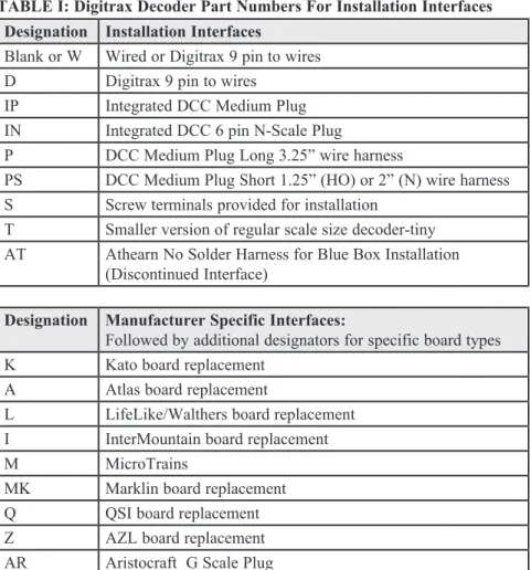
TABLE I: Digitrax Decoder Part Numbers For Installation Interfaces Designation Installation Interfaces
Blank or W Wired or Digitrax 9 pin to wires D Digitrax 9 pin to wires
IP Integrated DCC Medium Plug IN Integrated DCC 6 pin N-Scale Plug
P DCC Medium Plug Long 3.25” wire harness
PS DCC Medium Plug Short 1.25” (HO) or 2” (N) wire harness S Screw terminals provided for installation
T Smaller version of regular scale size decoder-tiny AT Athearn No Solder Harness for Blue Box Installation
(Discontinued Interface)
Designation Manufacturer Specific Interfaces:
Followed by additional designators for specific board types
K Kato board replacement
A Atlas board replacement
L LifeLike/Walthers board replacement I InterMountain board replacement
M MicroTrains
MK Marklin board replacement
Q QSI board replacement
Z AZL board replacement
Digitrax Decoder Numbering Examples:
DH163 is a series 3 wired decoder that fits HO scale, is rated for at least 1 amp & has 6 function outputs. This decoder is actually rated at 1.5 amps.
DH165A0 is a series 5 board replacement decoder that fits HO scale Atlas locomotives that use the version “0” board, is rated for at least 1 amp, has 6 function outputs and can host a sound only decoder.
SDXH166D is a Series 6 wired premium sound decoder that fits HO scale, is rated for at least 1 amp, and has 6 FX3 function outputs.
Visit our online Decoder Selector at www.digitrax.com/decoderselector for help selecting the best decoder for your locomotive.
3.0 Decoder Installation
Each Digitrax decoder comes with an instruction sheet that shows you the spe-cifics of how to install it in a locomotive. There are also additional installation application notes and installation videos available at www.digitrax.com/sup-port. The following sections explain decoder installation in general.
3.1 Decoder Installation Basic Steps
1. Choose a locomotive that runs well on regular DC because adding a decoder will NOT improve mechanical operation.
2. Choose the appropriate decoder for your installation. 3. READ the instructions.
4. PLAN the installation. 5. Have the proper tools on hand. 6. Test the decoder before installation.
7. Carefully disassemble the loco without losing any parts.
8. Isolate the motor! Current to the motor from the pick ups should flow only through the decoder and NOT through the frame. 9. Follow the decoder’s wiring diagram or installation instructions for
installing motor, sound and function components. 10. Test the installation first on DC then on DCC.
3.2 Choosing a Locomotive
Choose a locomotive that runs well on conventional DC power. Digital decoders don’t compensate for faulty motor operation, poor track pickup, or other problems with a locomotive’s mechanical operation. If you are not happy with the way your locomotive runs on DC power, installing a decoder will not make it run any better.
If there are mechanical issues with your locomotive, fix them before you install the decoder. Since you have to open up the loco anyway, do a tune up before you install the decoder. Digitrax recommends using a conductive brush lubri-cant like Aero Car Technology’s “Conducta” brush lubrilubri-cant (aerocarlubri-cants.com) to minimize brush noise in all locos. Be sure the brushes are mak-ing reliable contact and that the commutator is clean.
Decide where the decoder will fit inside the loco. Is there space to put the decoder or will you need to “make room?” Is there a decoder made specifi-cally for the loco? Digitrax offers a variety of decoder sizes, form factors and current ratings to accommodate almost any locomotive. Check the Decoder Selector at www.digitrax.com for a list of recommendations. If there is just nowhere in the locomotive to install a decoder, it can be installed in a piece of rolling stock that is wired to the loco for controlling the motor or you can run it on your Digitrax system as an analog locomotive on address “00.”
3.3 Choosing The “Right” Decoder
3.3.1 The Digitrax On-Line Decoder Selector
The Digitrax On-line Decoder Selector is an on-line list of decoder recom-mendations for specific locomotives. Visit www.digitrax.com/decoderselector to use the Decoder Selector. The Decoder Selector is also part of the Digitrax Toolbox App for mobile devices. Most Digitrax Authorized Dealers can also help you determine which decoder will work best in your locomotive.
4 Steps To Choosing the Right Decoder for Your Loco
1. Is there a decoder made for your specific loco? Check the Decoder Selector at www.digitrax.com/decoderselector for specific decoder recommendations for specific locomotives. If so, you can skip steps 2 & 3.
2. What is the stall current of the motor in the locomotive? 3. How much room do you have available inside the loco?
4. Do you want a decoder that does motor and function control and would you like to add sound? If you are planning a sound installa-tion, remember you’ll need to have room for the speaker and sound hold up capacitor.
3.3.2 What Is Your Loco’s Stall Current?
For HO locomotives, most modern high efficiency can motors draw less than 1/2 amp when running and less than 1 amp when stalled at 12V DC. These motors will use 1 amp & 1.5 amp decoders. Some older HO motor designs (older Athearn open frame motors, Pittman motors, etc.) may exceed these lim-its and will need a higher current decoder for better long term reliability. Most current production Digitrax decoders are rated for at least 1 amp, even if they
are designated as N or Z sized decoders. That means that our N & Z decoders are suitable for use in HO locomotives where space is tight.
For N & Z scale locomotives most modern high efficiency can motors draw less than 1/2 amp when running and less than 1 amp when stalled at 12V DC. However, we have found that many high performance N-scale locos actually draw more than this and are comparable to HO locos. To ensure long-term reli-ability, all current production Digitrax decoders are rated at 1 amp or more.
For large scale locomotives, it is particularly important to test the specific loco you will use to determine the appropriate decoder to use. In many cases for O, S, O-27 & G scale Digitrax 3, 4, or 5 amp decoders will the best choice. If your installation has 2 or more motors, you will need to consider the stall currents for both motors to determine the best decoder to use. In large scale, there are often variations in the way locomotives are built so, it is important to assess each individual locomotive before proceeding with decoder installation.
How to Determine The Stall Current Of A Locomotive
1. Place the loco (without the shell) on a track powered with regular DC at 12V for HO & N Scales (Use 16V for G Scale).
2. Attach a DC current meter (ammeter) in series with one of the track feeds. A power pack with an ammeter is good for this test. 3. Apply DC power to the track (12V for HO/N, 16V for larger
scales).
4. Stop the motor from rotating by holding the fly wheel or drive shafts for a couple of seconds and measure the current that the unit is drawing from the power pack while the motor is stalled. 5. Be sure that the power pack voltage remains at 12V (16V for G
Scale) during this test to be sure you get an accurate stall cur-rent measurement.
6. Choose a decoder with at least the current rating determined with this test. Digitrax recommends using the decoder with the high-est current rating that will fit in your locomotive for long term reliability.
3.3.3 Which Decoder Will Fit?
The space available inside the locomotive is a major factor in choosing which decoder to use for your installation. Many sizes & form factors are available. Visit www.digitrax.com/decoderselector to see our recommendations for many locomotives. Complete information, including size measurements, for each decoder is available in the product section of the website. Instruction Sheets
for specific decoders which include installation examples are also available on our web site. Our website has decoder installation videos to guide you and your local dealer can show you examples of decoders and help you determine the best one to use for your installation.
For installations in small spaces, Z and N scale decoders are rated at 1 amp or more and will work fine in HO scale locomotives.
The Digitrax Tech Support Depot at www.digitrax.com/support, has links to application notes and videos for installations in many different locomotives.
3.3.4 Decoder Interfaces for Installation
Each locomotive has its own set of issues surrounding installation. Current production locomotives often have easy installation interfaces that allow you to simply plug in a decoder or replace a circuit board inside the loco. Other locomotives, particularly really small ones, may require a soldered installation. Sound decoders are a challenge because of speaker & hold up capacitor instal-lation requirements in addition to the decoder itself.
3.3.4.1 Plug ‘N Play and Board Replacement Interfaces
Many locomotives come from the factory with provisions for decoder instal-lation. Some locomotives come with the decoder pre-installed. Manufacturers use several terms for these locos. Be sure to read the box and examine the loco so you know what you are getting. Some “plug ‘n play/board replacement” decoders require special installation steps. Be sure to read the instructions.
DCC Ready Locomotives: These locomotives are usually equipped with a DCC medium socket, though you may find some locos where this terminology means that there is room for a decoder. Be sure to check this before purchas-ing the locomotive
DCC Medium Socket: This diagram shows the DCC medium plug that is widely used with HO locomotives that come from the manufacturer with the DCC medium socket. The color code refers to the wire colors on a DCC wire harness. To install a decoder in a loco with a DCC medium socket, remove the dummy plug that comes with the locomotive and insert a decoder with a DCC medium plug in the socket.
1
2
3
4
5
6
7
8
Black Not Used Yellow Orange
Red Blue White Gray
Digitrax offers the DCC medium plug in three variations:
IP - Integrated Plug where the DCC medium plug is built in to the decoder itself with no wires.
P - DCC Medium Plug on a long harness with 3.2” wires for installation where the decoder body will be located away from the socket site.
PS - DCC Medium Plug on a short harness with 1.2” wires for installation in HO Scale and 2” wires for installation in N Scale where the decoder body
will be near the socket.
Digitrax 9 Pin HO: The Digitrax 9 pin socket & plug is another commonly used DCC plug ‘n play interface that is available in some HO locos.
Integral 6 Pin N Scale Socket: The 6 pin integral socket is used in N scale locomotives where 8 pins won’t fit. The 6 pin “IN” type decoders have 6 fine pins integrated into the edge of the decoder to fit the socket. Also called NEM651 plug.
Board Replacement Decoders: In this case decoders are designed for specific locomotives. Board replacement installations require you to remove an existing circuit board and replace it with a board replacement decoder. This may involve adding insulating tape inside the loco and/or building up solder pads to insure good electrical contact. While not always completely “plug ‘n play,” board replacements are usually much more convenient that wired installations.
Decoder Equipped Locomotives: These locomotives are equipped with decoders at the factory. These pre-installed decoders may have minimal fea-tures. If you want additional features, you may wish to replace the decoder that came with a loco with one that has more features. In some cases you have the option to purchase a loco with or without a decoder. Evaluate the features offered before deciding which one best fits your needs. DCC compatible decoders shipped with locomotives should work with your Digitrax system but will not have the same feature set as you Digitrax decoders.
3.3.4.2 Digitrax 9 Pin HO & 8 Pin N Decoder Interfaces
Some Digitrax HO & N scale decoders come with a plug and socket on the decoder so that the wire harness can be unplugged from the decoder. This inter-face lets you share one or more decoders among multiple locomotives wired with the corresponding harnesses and lets you use dummy plugs for operation on DC.
Wire Harnesses: DHWH (9 pin for HO) and DNWH (8 pin for N) have a plug that attaches to your decoder and wires that are soldered to the motor, brushes and functions on your locomotive during installation. The HO wire harnesses also come in both short and long versions with a plug on one end and DCC medium plug on the other end. The N scale version comes in the short version only with the DCC medium plug.
Dummy Plugs: DHDP (HO) and DNDP (N) are available for DC operation of harnessed locomotives (without decoders). When you install a wire harness in your locomotive and plug a dummy plug into it, your loco will operate on any analog control system and will run on DCC as an analog loco. When you remove the dummy plug and plug in a decoder, the loco will run on DCC.
To separate a Digitrax decoder from the Wire Harness:
Firmly hold all harness wires between thumb and forefinger approximately 5/8” back from the plug. Grasp the decoder body on the sides right next to the socket to ensure no stresses are placed on components under the protective sleeve. Pull gently and evenly on all wires simultaneously. Distribute the force needed to separate the plug and socket EVENLY over all the wires to prevent damage to the plug.
3.3.4.3 Installing Decoders with Wires
In some cases, especially in older locomotives, brass locomotives and really tiny locomotives, there is no special harness arrangement, plug ‘n play installation or board replacement option available. In these cases, the decoder wires are soldered into the locomotive.
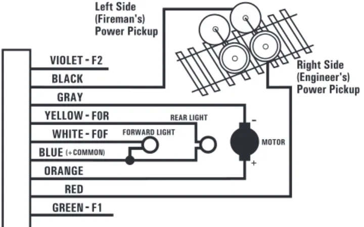
Refer to TABLE II for Digitrax Mobile Decoder Standard for Wire Colors and Figure 1 Digitrax Decoder Wiring Diagram for general instructions and the specific Decoder Instruction Sheet that came with your decoder for specific instructions for the decoder you are installing. See Figure 2 for lamp installa-tion informainstalla-tion.
TABLE II: Digitrax Mobile Decoder Wire Colors
What the wires are for Wire Color
Power Pick-up Right (Engineer’s Side) Red Power Pick-up Left (Fireman’s Side) Black
Motor + Right Brush Orange
Motor - Left Brush Grey
F0(FWD)-Forward Light White
F0(REV)-Reverse Light Yellow
Lamp Common Blue
F1-Function 1 Green
F2-Function 2 Violet
F3-Function 3 Brown
F4-Function 4 White w/ Yellow Stripe
F5-Function 5 White w/ Green Stripe
F6-Function 6 White w/ Blue Stripe
Figure 1: Digitrax Decoder Wiring Diagram
Figure 1 Notes:
Do not exceed the decoder’s total function output current rating. Blue (+ com-mon) must be hooked up to enable transponding. If Blue (+ comcom-mon) is not used, connect function power to either track power pick up. The directional light function “Lamp Return Line” can be hooked to Blue (+ common) as shown or to either track pick-up.
3.3.5 Decoder Features-LocoMotion
Features control the movement of the locomotive and other operating charac-teristics. Digitrax LocoMotion® System lets you customize your locomotive so it runs like the real thing. These LocoMotion features are set up using CVs to customize the locomotive’s operation.
LocoMotion includes normal direction of travel, use of 3 step or 128 step s to customize throttle response, acceleration and deceleration rates, start-mid-max voltage settings, torque compensation, switching speed, consisting (basic, advanced or universal) and more.
3.3.6 Decoder Functions-Lights, Sound, Etc.
Once you have determined the current rating and decoder size needed for your loco, consider what lighting and other on/off items installed in the locomotive you want to control from your throttle.
Functions are generally used for lamps, LEDs, uncoupling devices, controlling sound and other low current draw features you want to be able to control from your throttle. All Digitrax decoders are equipped with two or more function outputs that are used to turn functions on and off and set up special lighting effects called FX3. You can have reversing headlights or independently con-trolled headlights. You can map functions to operate on specific throttle keys. Series 6 decoders have lighting algorithms that are selectable for either lamps or LEDs. If you are using smoke generators or other high current devices, make sure you do not exceed the specified function current.
Function outputs can be in the form of :
1. Leads (wires) soldered to the decoder at the factory that are used to hook up functions.
2. Pre-wired function outputs that work when the decoder is installed. The forward and reverse lights on board replacement decoders are an example of pre-wired functions.
3. Solder pads on the decoder where function wires can be soldered by the end user.
Some decoders have more than one form of function output. For exam-ple, the DN163K0A has two function outputs pre-wired to the white LEDs on the decoder and 4 additional solder pads available for add-ing wires to hook up more functions.
Check the decoder’s specifications to determine how many function outputs a particular decoder has available. Function only decoders, like the TL1 & TF4, can be used in addition to mobile decoders to add more standard on/off func-tions. TL1 & TF4 do not have FX3 capabilities.
Digitrax FX3 functions incorporate up to 8 FX generators that can be custom-ized. These FX3 function outputs can be mapped so they are controlled by any function key on your throttle. A master light switch can be set up to turn off all lights on a locomotive. Functions associated with advanced consists can be controlled, too.
Function outputs on Digitrax decoders are available in several current ratings depending on the decoder. These ratings are the total current available for activating and running the devices attached to ALL the function outputs on the decoder. Check your specific decoder’s specifications for the function current rating for your decoder.
3.3.7 SoundFX Decoders
Sound inside your locomotive is another factor to consider in decoder selection. Because sound installation requires additional space inside the locomotive for installing a hold up capacitor and a speaker with baffle, this must be considered during decoder selection.
3.4 Read the Instructions
Digitrax decoders are shipped with individual instruction sheets. These have specific instructions for each particular decoder. These are also available on-line along with installations that demonstrate how to do many different decoder installations.
3.5 Plan the Installation
Planning ahead will make decoder installation easier to do.
3.6 Have the Proper Tools At Hand
You’ll need a few simple tools when you begin installing decoders: 1. A temperature controlled low wattage soldering iron. Though many
installations do not require soldering, you may need to use a solder-ing iron to install LEDs and lamps for special lightsolder-ing effects. 2. 0.015”-.032” rosin core solder for electronics
3. Small screwdrivers and small shims for disassembling your loco. 4. Small diagonal cutters for cutting & stripping small wire. 5. Tweezers to pick up small loco parts.
6. Heat shrink tubing for protecting wire connections, electrical tape is NOT recommended.
7. Tape for securing wires and the decoder inside the locomotive. Digitrax provides Kapton tape with many decoders for electrically insulating the locomotive frame.
8. Decoder installation should be done in a static free environment on a non-metallic surface.
3.7 Testing Decoders Before Installation
Digitrax tests each decoder prior to shipping. That said, we strongly recom-mend testing by the installer before installation. The test procedure shows you how the decoder works and how to hook up the wires. Testing verifies that the decoder is working before you install it in a loco. Use the LT1 that came with your Digitrax Starter Set to perform the test as follows:
LT1 Diagram
(Top view-clip on top)
Wire order in RJ12 plug Blue Yellow Green Red Black White
HARNESS
LT1 TESTER
Decoder Testing Diagram
R FUNCMU SWCH R c LOCO Y + L t C B A BACK OPTN CLOC PWR 10 11 12 1 2 3 4 5 6 ENTER 0 EXIT 7 8 9 DISP PROG EDIT FIND _ R L D T 4 0 2 N EMRG STOP
Note: Recommended decoder input voltage is 12V DC peak
Digitrax Throttle must be plugged in during LT1 testing Protection Resistor 100 Ohm/2Watt
LT1 Decoder Testing Instruction
s
1. Strip the insulation from the red and yellow wires and twist them together.
2. Strip the insulation from the green and black wires and twist them together.
3. The blue and white wires are not used. They can be left on the har-ness.
4. Hook up decoder as shown here. If your decoder does not have wires, use alligator clips to make the appropriate connections to the pads or pins on your decoder.
5. Use your throttle to select the decoder and run it in the forward direc-tion.
6. One of the two center LEDs will light as the motor voltage increases. Change direction and the other LED will light.
7. Test the decoder function outputs by connecting the LT1 to the blue lamp common and one of the function outputs.
8. Use your throttle to turn the function on and off . One of the two cen-ter LEDs will go on and off with the function. Do this test for all function outputs separately.
Note: The LT1 can also be used to test LocoNet Cables by plugging in one end of the cable being tested into the LT1 and the other end into your command station or booster. At least one Digitrax throttle or Zephyr all-in-one unit must be plugged in to LocoNet. If all four LEDs light, the cable is good. Note that the LEDs may not all be the same brightness, this is normal. If any of the LEDs fail to light, remove the plug from on end of the cable and re crimp another one prior to re-testing the cable. Digitrax LocoNet Cable Maker Kit has everything you need to make repairs to LocoNet Cables.
3.8 Locomotive Disassembly
Before you begin, read the instruction sheet that came with your decoder. It is not possible for this manual to cover the specifics of each decoder individually, these are provided with the individual decoder and are also available online at www.digitrax.com.
1. Read the locomotive manufacturer’s disassembly instructions. Many of these are available online. Making photos of the loco as you take it apart can be a big help later if you need to go back.
2. Disassemble your loco carefully. You’ll need all the little parts later. 3. Note how + and - motor connections & the left & right power pick up
connections are set up.
4. Look carefully at the loco’s wiring & determine where all the wires go and what they do before changing or disconnecting any of them. The physical location of the decoder in the loco is important and may involve sculpting plastic and or metal parts to allow enough room for installation. Install the decoder in the coolest part of the loco body. Recommended oper-ating temperatures should be between 70 & 120 degrees Fahrenheit (20-50 degrees Celsius).
When making wire connections inside the loco, use the shortest length of wire that will do the job. After the wires are attached and insulated with heat shrink sleeving, secure them so that repeated removal and replacement of the locomo-tive shell won’t pull the wires loose. The biggest cause of decoder failure after initial installation is wires being pulled loose and shorted to the frame when the shell is removed or replaced.
3.9 Electrically Isolating the Motor
Failure to isolate the motor will damage your decoder. For DC permanent magnet powered locomotives, the decoder must be electrically inserted between the track power pickups and the 2 motor brushes.
The most important part of any successful locomotive conversion is proper electrical isolation of the 2 motor brush connections, so that they are driv-en only by the decoder.
Once the motor is isolated, visually inspect the brushes again, just to be sure. Use a continuity checker (beeper box) to be sure there is an OPEN circuit (very high resistance) from both brushes to any other part of the locomotive chas-sis, power pickups and wheels. Check both motor brushes. If the circuit is not open, your beeper box will beep.
Only when you are satisfied that the motor is isolated, should you proceed with the decoder installation
.
Some motor brush power connections may be tricky, like a spring to or inter-ference fit with part of the chassis. Some locos pick up brush power from the chassis through a spring. In this case, after removing the spring connection to the brush, wire the corresponding decoder power input to the chassis. Examine the loco carefully to determine how power moves from the track pickups to the motor.
Decoders with FX3 functions have motor isolation protection. If the decoder
senses that the motor is not isolated, it will not run the motor. In this case, you will be able to control the loco’s functions but the motor will not work. For board replacement decoders, it is important to follow the Decoder Instruction Sheet for the particular decoder when installing insulating tape inside the loco to prevent shorts during operation caused by the decoder board shifting inside the engine.
Reverse Lamp Yellow Lamp Common
Forward Lamp White Reverse Lamp Yellow
Operation With Blue Lamp Common Connected
Lamp Common
Forward Lamp White Reverse Lamp Yellow Lamp Common Blue
Forward Lamp White LED Cathode End
LED Cathode End Preferred method.
Lamp brightness won't vary when analog locos are operated on the layout.
Transponding can be enabled.
*
*
*
*
*
*
Figure 2: Lamp & LED Wiring Diagrams
1.5V Lamps
12V to 16V Lamps
LEDs
+
- +
-Note: LEDs are sensitive to polarity when hooked up.
Typical resistor values range from 680 ohm to 1.5 kohm 1/4 watt.
*
Note: Current setting resistor. Typically 560 ohm 1/4 watt for grain of rice and 250 ohm 1/4 watt for grain of wheat.
Lower resistance values to increase lamp brightness, min value is 100 ohms.
Values vary depending on track voltage in use.
*
Forward Lamp White Reverse Lamp Yellow
Operation Without Blue Lamp Common Connected
Forward Lamp White Reverse Lamp Yellow
Right Rail Pickup
Left Rail Pickup Right Rail Pickup
Left Rail Pickup Forward Lamp White
Reverse Lamp Yellow
Left Rail Pickup Right Rail Pickup LED
Cathode End Cathode EndLED
Use to save space in installation.
Lamp brightness varies depending
on the direction of the analog locomotive.
Transponding can’t be enabled.
*
*
-
3.10 Installing Lighting Effects
Adding lights to your locomotives can bring an added degree of realism but there are a few things to consider.
Headlight and Rear Light Operation
Automatic headlight reversing: All Digitrax decoders are shipped with auto-matic reversing headlight operation as the default.
Non-directional (independent) headlight operation: If you do not want auto-matic reversing headlight operation use CV33 & CV34 to map F0Fwd and F0Rev to operate on two different throttle function keys.
FX3 light operation: Refer to the FX3 Section 9.0 which details how to program the many different FX3 effects.
Additional Lamp and Function Wiring Considerations
Lamps with current draw over 50mA: For regular 12 to 16 volt lamps that draw more than 50mA when lit, we recommend using a 22 to 33 ohm 1/4 watt resistor in series with the lamp leads to avoid the lamp “start-up cur-rents” overloading the outputs. These start-up currents can be up to 10 times the normal current draw.
Loco with only one lamp: If the locomotive has only one lamp, connect the F0Fwd (white) and F0Rev (yellow) outputs together. In this case the single light will be on if F0, the light function, is turned ON.
Connecting additional function outputs: Connect F1-F6 to the lamps or other items you want to control. Be sure not to exceed the total output current rat-ing of the function outputs for the decoder you are usrat-ing.
Transponder equipped decoders: All Digitrax Series 3, 4, 5, & 6 decoders have built in resistors for transponding. Earlier versions of Digitrax decoders may need to have a load resistor installed for transponding to work. Please consult instructions for those specific decoders. You may see a slight glow even when the forward light is turned off, this is normal.
3.11 Installing Power Xtenders
Digitrax Power Xtenders are available for most Series 6 decoders. They are designed to keep locomotives running and sound from dropping out in situations where power to the locomotive is interrupted due to dirty, dead or bad track. Hold up time varies based on actual decoder load and track conditions.
Most Series 6 mobile decoders include either solder pads, a 2 pin socket or a sound harness replacement for adding a PX module to the decoder. Some very small Series 6 decoders cannot accommodate power xtenders because there is no room available on the board. No CV configuration is required to add a power xtender module and most are plug ‘n play installs. See www.digitrax.com for more information about Digitrax Power Xtenders
3.12 Final Decoder Test
Once the decoder is installed, you are ready for the test track. For decoders with FX3functions, if you are able to control the loco’s lights but the motor
will not run, this is also an indication of a motor short circuit that must be cor-rected.
1. Place your Digitrax decoder equipped locomotive on the programming track and try to read or write to the decoder. If you get a program-ming error, check your wiring. This allows you to test the decoder in a low current environment to avoid damage due to incorrect wir-ing or installation.
2. Run your Digitrax decoder equipped locomotive on a regular DC track with the positive polarity connected to the right side wheels. The Digitrax decoder in the locomotive will recognize that it is not receiving DCC commands and automatically convert to analog mode, this is called analog mode conversion.
3. Using a DC power pack, move the loco in the forward direction. If the loco moves in reverse, the input power feeds to the decoder are reversed. Power down, swap the decoder power input connections (red & black leads) and try again.
4. Next, run the decoder equipped loco with your Digitrax system. Follow the instructions in your Digitrax Starter Set manual to select and run the locomotive on address 03. Operate any functions installed to be sure they can be turned on and off. Since you have not programmed the decoder yet, the decoder will use the factory default settings.
5. If any problems are observed, make corrections to your wiring and re-test.
3.13 Avoiding Heat Problems with Installations
Most HO & N Scale locomotive motors, LEDs, and lamps are designed to operate on 12 volts DC on the track. Z Scale equipment is designed to run at 9 volts. Digitrax recommends running your command station and boosters at the lowest track voltage possible that provides acceptable operation.
The “N” (12V) setting on Digitrax command stations and boosters works well for most HO & N scale layouts. The “HO” setting should be used only for HO and larger scales. We recommend using a UP6Z Voltage Reducer for Z scale layouts to avoid applying too much track voltage to Z scale equipment.
If the track voltage applied exceeds the operating parameters of the locomotive and it’s LEDs/lamps, damage to the locomotive or decoder may occur.
4.0 General Decoder Troubleshooting
4.1 The decoder won’t respond
Make sure track power is ON
If the throttle is indicating that track power is off, turn track power on.
Can you control the functions but not the motor?
If so, remove the loco from the track and check your installation for motor iso-lation or short circuit problems.
Can’t select the loco address on your throttle
1. If you see STEAL=Y? or stL? on your throttle display, the loco is in use by another throttle. Release the loco from the other throttle before proceeding.
2. If you see consist or cn, the loco is part of a consist and can’t be selected individually. Remove the loco from the consist before con-tinuing
Check the value programmed into CV29
If your decoder is a 14 step decoder running on a system that is sending 28/128 speed step commands, status editing is necessary to make the commands sent by the system match what the decoder can handle.
Have you reset any CVs since the last time you ran the loco?
If so, go back and change them to their default values and then try to run the loco. It is possible to set acceleration so high that it will take 10 minutes for the loco to start moving.
Does your throttle say slot=max or FuLL?
This means that the system’s capacity to handle operating locos is full. If you have the slot=max or FuLL message, be sure that all locos that are not running are released from throttles. Check your command station manual to determine how many locos your system can handle at a time.
During decoder programming, slot=max or FuLL message will be displayed if the loco you are trying to program has too many current loads attached. If this is the case, you need to remove some of the extra loads to program the decoder. This happens with locos that have many lamps installed or where the lamps are wired directly to the track pickups.
If all else fails, reprogram the decoder’s address and reset CVs to default values by setting CV08 to 08 to reset everything or to 09 to reset every-thing except loadable speed table and sound project selection entries.
4.2 The decoder runs for a while & then just stops
If a decoder is hot to the touch, it may be overheating
It is normal for decoders to warm up while in use but they should not be hot to the touch. Be sure the decoder is installed so that it can shed heat. Don’t put decoders near the motor or lights.
Check for localized track problems
Be sure you are not on a section of track that is not powered or does not have enough power. Use the Quarter trick described below to diagnose this condi-tion.
4.3 Loco operation is jerky & erratic
Is the track clean and are the power feeds reliable?
Are the locomotive wheel pickups and internal electrical connections reliable? The majority of intermittent operation faults can be traced to bad connections and poor or noisy wheel pickups on locomotives. Series 6 decoders can use a Power Xtender module to improve operation of both motor and sound in the presence of power interruptions.
4.4 “Strange” locomotive light operation
If you can’t control the operation of the lights in your locomotive with your throttle (in default 128, or 28 speed step mode), be sure that the decoder is programmed for advanced 28 speed step mode. Your Digitrax decoder was shipped programmed to 128 speed step mode. You may have changed your decoder’s programming when performing the decoder test procedure. In any case, if you are not able to turn the locomotives lights on and off, you will need to change CV29 to 006 or another appropriate value that sets the decoder to advanced 28/128 speed step mode.
If you can’t turn the lights on and off or the lights blink when you run the loco, make sure you are not running a standard (14 speed step operation) decoder trying to process 28 speed step Advanced packets. Be sure that the decoder and command station are using the same mode by programming CV29 to an appro-priate value or by changing the command station’s operating mode to match the decoder.
4.5 The locomotive won’t move at all
Does the locomotive have any mechanical binding problems? Is there any-thing inside the loco that is preventing the motor from turning? Are any wires shorting or touching moving parts?
When you are operating a Digitrax Command Station set up to run in 128 speed step mode, there are some decoders that only understand 14 speed step
mode. If you are using one of these non-Digitrax decoders, you will need to status edit the decoder so that it will run.
4.6 Locomotive “buzzes”
Most noisy locomotive issues are caused by vibrations inside the loco’s mecha-nism. For DCC equipped locos, try lubricating the locomotive’s brushes and tuning up the loco’s mechanism.
Analog locos (without DCC decoders) make a “singing” sound when sitting still on DCC layouts. This noise, which is caused by the DCC track signal, decreases as the analog loco is accelerated. You can significantly reduce this noise by using conductive brush lubricants and by assuring that there is no vibration inside the loco that will add to the noise generated.
When operating analog locos on DCC layouts, DO NOT leave analog locos sit-ting still. It is best to park them off the live track unless they are running. This will prevent heat build up that can damage the loco, minimize the humming noise and lessen stress on the motors.
4.7 The Quarter Trick
If your track does not have adequate power supply to the locomotives, then the DCC signal won’t get through either. Use a coin or screwdriver blade and go around your layout creating electrical shorts every 10 feet. Your boosters should indicate a short by beeping (or in the display for Zephyr units) and shut down track power when the short is present. When the short is removed, the booster will return to normal operation. If this does not happen, then you need to add more feeders to make sure the track has enough power supply to oper-ate.
4.8 Are your LocoNet Cables built correctly?
Check your LocoNet cables with the LT1 tester to be sure the cables are good. If your LocoNet cables are not working correctly, the signal won’t get through.
4.9 Getting Help
Don’t suffer in silence! There is no such thing as a “dumb question!” Our website, www.digitrax.com, and Tech Support Depot have the answers to many commonly asked questions. These are always available. If you can’t get it to work the way you think it should, let us know! Often your local Digitrax deal-er will be able to help you work out any problems you may encountdeal-er. If not, please contact Digitrax directly. Our support staff is available Monday through Friday 8AM to 5PM CDT to help you. E-mail [email protected]. We have found that e-mail is the most efficient way to handle tech support ques-tions. Often, we can send you written instructions to solve your issue. If that does not work, we will call you for further assistance.
5.0 Decoder Programming
5.1 What are Configuration Variables (CVs)?
Each Configuration Variable, CV, controls one or more operating character-istics of the decoder based on the CV value that you program. All Digitrax decoders come with default settings from the factory that will run “out of the box.” Before you start programming your decoders, it’s a good idea to run your decoders with the default values that come pre-programmed from the fac-tory. This will let you get used to using DCC before you begin customizing. In many cases, you will find that you only need to change the address of the loco-motive to have great operation.
Once you are ready to customize, you can pick and choose from among the CVs and program each one independently. Once these CV values are pro-grammed, they are “remembered” in the decoder until you reprogram it with a new value. If you decide to use deceleration, in particular, keep the pro-grammed CV values small so that you have time to adapt to the delays in deceleration you have set up without crashing your valuable locomotives! See the Configuration Variables section below for complete information on how CVs are used by Digitrax decoders.
5.2 Service Mode and Ops Mode Programming Methods
Digitrax supports two programming methods:
Service Mode Programming is done on an electrically isolated programming track. In service mode, the command station broadcasts programming infor-mation to all decoders on the programming track. Direct, paged and physical register modes are used for service mode programming.
Operations Mode Programming, also called Ops Mode or programming on the main, is done on the layout by sending programming commands to a spe-cific locomotive address. To use this mode, you must have decoders that are capable of operations mode programming.
5.3 Programming Modes
Digitrax Command Stations support direct, operations mode, paged, or physical register programming methods. This gives you maximum flexibility to program DCC decoders made by different manufacturers at different times in history.
Directmode is the most commonly used programming method. Digitrax rec-ommends using direct mode for programming on the programming track.
Paged mode also gives access to all CVs for programming. Direct and paged programming appear very similar to the user.
Operations mode programming allows programming of decoders while the locomotive is on the mainline without having to use the programming track. The decoder address can be programmed with Ops mode programming with Digitrax DT300 & DT4xx series throttles. Some DCC systems allow operation mode programming only for CVs other than address.
Physical register mode is a very basic mode for programming decoders. With “register mode” you can program CVs 01, 02, 03, 04 & 29 only. This is only used with older decoders that require this method.
All of these programming modes may or may not be supported by your non-Digitrax command station or programmer. For the specifics and mechanics of programming with your system, please check your command station or pro-grammer manual.
5.4 DCC Outputs: Programming & Layout Operation
The DB150 Command Station/Booster, has one DCC output that is used both to run the trains and to program decoders. For this kind of command station, you will have to shutdown layout operations to program in service mode. The DCS100/DCS200 Command Station/Boosters and the DCS50/DCS51 Command Station/Booster/Throttle Combos have two DCC outputs. This means that you can program in service mode and read back decoders without having to shut down the layout. Both single and dual DCC output systems require a service mode programming track unless you are using operations mode programming on the main.
5.5 Reading & Writing CVs
The DB150 Command Station/Booster has a “write only programmer,” it will program CVs to the values you choose. DB150 will not read back CVs and their values programmed into your decoders.
The DCS100/DCS200 & DCS50/DCS51 Command Stations are “read/write programmers,” they can program decoders and read back their CVs and values. Another programming option is to use a PR3 Xtra programmer and your com-puter to program and read back decoders. Other DCC compatible programmers are able to program Digitrax decoders as well. Consult the manual for the sys-tem you are using for complete programming instructions.
Digitrax FX3 decoders have operations mode read back capabilities when used on layouts instrumented for this feature.
Note: Some DCC systems use a low power setting for all decoder program-ming. Digitrax recommends that you use low power programming for initial decoder tests prior to installation in the locomotive. We do not feel that it is
necessary to use a low power setting for decoder programming once you have successfully installed the decoder in the locomotive. If you are reprogramming an installed decoder, feel free to follow the steps presented here. If you wish to use a low power setting for decoder programming, please see the decoder ini-tial test procedures in Section 3.7 which detail the use of a protection resistor to provide a low power programming option.
6.0 CVs-Configuration Variables
Configuration Variables or CVs are special storage locations or “pigeonholes” in the decoders. By programming CV values into CVs you can customize each decoder’s performance characteristics. These characteristics are permanently “remembered” by the decoder even when the power is off. CV values can be changed as often as you like. The meaning of most CVs is set by industry stan-dard. There are also some manufacturer specific CVs that are defined by each manufacturer to accommodate their own special features. Some legacy decod-ers do not use the same CVs that are currently in standard use.
At first glance, you will see that there are many different CVs. This may seem confusing but, don’t worry, Digitrax decoders are shipped with a set of pre-programmed factory default values that let you get up and running right away. As you begin to explore the possibilities with DCC, you will probably repro-gram CV01, the decoder’s 2 digit address. This lets you run more than one locomotive at a time. You may need to make changes to CV29, the “configura-tion” CV to make your lights operate correctly. Next you may decide to set up acceleration (CV03) and deceleration (CV04) or you may wish to set up your FX3 options using CVs 49 through 63 As you explore more of the capabilities of your decoder and system refer to TABLE III as a guide.
Digitrax decoders use many different configuration variables (CVs) to control the operating characteristics of the decoder. CV usage is fairly standardized from decoder to decoder but there may be differences in how CVs are used by different manufacturers.
To be absolutely sure about which CVs a particular decoder uses for a particu-lar feature, the range of values available and the factory default value please consult the specification sheet available on each decoder’s product page on www.digitrax.com. This will give you a complete list of CV uses for each individual decoder.
Sound projects are totally customizable and CVs may not be used consistently from project so project. Information on CVs used in sound decoders is includ-ed with each sound project.
Visit our online CV Calculator at www.digitrax.com/support/cv/ for help with determining the best CV Value to program into a CV.
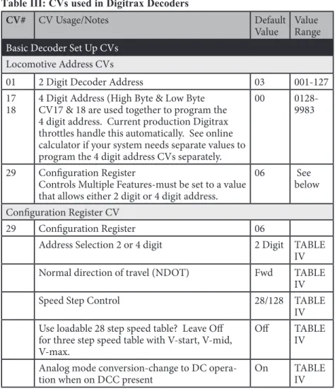
Table III: CVs used in Digitrax Decoders
CV# CV Usage/Notes Default
Value Value Range
Basic Decoder Set Up CVs
Locomotive Address CVs
01 2 Digit Decoder Address 03 001-127 17
18 4 Digit Address (High Byte & Low ByteCV17 & 18 are used together to program the 4 digit address. Current production Digitrax throttles handle this automatically. See online calculator if your system needs separate values to program the 4 digit address CVs separately.
00 0128-9983
29 Configuration Register
Controls Multiple Features-must be set to a value that allows either 2 digit or 4 digit address.
06 See below Configuration Register CV
29 Configuration Register 06
Address Selection 2 or 4 digit 2 Digit TABLE IV Normal direction of travel (NDOT) Fwd TABLE
IV Speed Step Control 28/128 TABLE
IV Use loadable 28 step speed table? Leave Off
for three step speed table with V-start, V-mid, V-max.
Off TABLE IV Analog mode conversion-change to DC
CV# CV Usage/Notes Default Value Value Range
LocoMotion CVs-Control locomotive motion characteristics
Acceleration and Deceleration
03 Acceleration Rate-128 steps 00 00-31 04 Deceleration Rate-128 steps 00 00-31 Three Step Simple Speed Table & Start Voltage (Simple Throttle Response Curve)
02 Start Voltage-128 Steps 00 00-255 05 Maximum Voltage-128 Steps
00, 01 & 255=voltage at step 28 00 00-255 06 Mid Point Voltage-128 steps
00 & 01=Straight line curve 00 00-255 Loadable 28 Step Speed Tables with 256 Step Resolution (High Resolution Throttle Response Curve-128 speed step interpolated)
65 Kick Start Value 00
66 Forward Trim 00
67 First Speed Table Entry 00 68-93 28 Step Speed Table Entries 00 94 Maximum Speed Table Step 00
95 Reverse Trim 00
29 Configuration Register-Must be set to a value that enables speed tables. Speed Tables Are Dis-abled in the default settings
06 See CV29 above Torque Compensation and Switching Speed
54
Val-ue Switching Speed Torque Compensa-tion
Decoder Lock
00 Off On Enabled
01 On On Enabled
16 Off Off Enabled
17 On Off Enabled
64 Off On Disabled
65 On On Disabled
80 Off Off Disabled
81 On Off Disabled
00 00, 01, 16, 17, 64, 65, 80, 81
CV# CV Usage/Notes Default Value Value Range Scaleable Speed Stabilization (Back EMF)
55 Static compensation 128 00-255
56 Dynamic compensation 080 00-255 57 Amount of Back EMF (Intensity)
See Scaleable Speed Stabilization Section for Range
06 See CV57 section Advanced Consist Address
19 Advanced consist address-default is off 00 00-255 Transponding and LED/Lamp Selector
61 CV
Value Transponding LED or Lamp
00 Off LED
01 Off Lamp
02 On LED
03 On Lamp
00 00-03
SuperSonic (Quiet Operation)
09 Motor Frequency-Default is Max 00 00-255
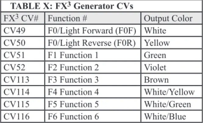
Function CVs for controlling lights, etc.
49 F0F, Forward light effect (white) 00 TABLE 50 F0R, Reverse light effect (yellow) 00 TABLE 51 F1, Function 1 (green) 00 TABLE 52 F2, Function 2 (violet) 00 TABLE 113 F3, Function 3 (brown) 00 TABLE 114 F4, Function 4 (white w/yellow stripe) 00 TABLE 115 F5, Function 5 (white w/green stripe) 00 TABLE 116 F6, Function 6 ( white w/blue stripe) 00 TABLE 62 FX Rate and Keep Alive Adjustment 00 00-255 63 Ditch Light Blink Hold Time 00 00-255 Function Mapping CVs set up throttle key for each function output
33-46 Function mapping CVs 00 TABLE XVIII Advanced Consist Function Control
21 Advanced consist function control override for
CV# CV Usage/Notes Default Value Value Range 22 Advanced Consist function control override for
F0 & F9-F12 00
Decoder Utility CVs
Decoder Reset
08 Reset decoder to factory default CVs Value Action
08 Reset all to factory default 09 Reset to factory default except
speed tables and selected sound scheme.
129
Decoder Lock
15 Selects the target decoder for programming commands
0=Decoder Lock Off 1-7=Unique decoder IDs
0 0-7
16 Sets the ID number of each decoder installed in a locomotive
0=Decoder Lock Off 1-7=Unique decoder IDs
0 0-7
Decoder IDs
105 User private ID #1 00
106 User private ID #2 00
07 Version ID-Read Only 64
08 Manufacturer ID-Digitrax 129
7.0 Basic Decoder Setup CVs
The decoder’s address and the configuration register CVs are the basic CVs needed to operate a decoder.
7.1 Decoder Addresses
The decoder’s address is the unique identification number that lets that decoder recognize commands sent to it by the command station. Once you program the decoder’s address, it is remembered by the decoder until it is changed.
Decoders can be programmed with both 2 digit and 4 digit addresses but only one or the other will be in use at any time. Whether the 2 or 4 digit address is used is determined by CV29, the configuration register.
You can change the decoder address by reprogramming it at any time so, you can set up any numbering scheme you choose for your locos. Many people assign the last two numbers of the loco’s road number as the 2 digit decoder or 4 digits of the road number as the 4 digit address.
More than one loco can be programmed to the same address. This is useful if you want to set up a basic consist and run more than one loco on a single address.
Digital Address Ranges for Mobile Decoders
Address “00” is used for analog operation of a locomotive without a decoder on the same track as DCC equipped locos.
Addresses from 001 to 127 are the two digit address range. Two digit decoder addresses are set up by programming CV01 & CV29.
Addresses from 0128 to 9983 are the four digit address range. Four digit decoder addresses are set up by programming CV17, CV18 & CV29.
There is no “three digit address.” If your loco only has a three digit road number, you can use 0-127 as a 2 digit address or use a 4 digit address with a leading 0.
7.1.1 Decoder 2 Digit Address: CV01
On your DT300 & DT4xx throttles, the display will show Ad2 for two digit addresses and Ad4 for four digit addresses. All other CVs are displayed as numbers on Digitrax throttles. Be sure that CV29 is programmed to a value that enables 2 digit operation. See CV29 below for more information.
7.1.2 Decoder 4 Digit Address: CV17 & CV18
The 4 digit address is sometimes called the long address. It is programmed in CV17 & CV18. Simply programming CV17 & CV18 will not enable 4 digit addressing. The DCS50, DCS51, DB150, DCS100 & DCS200 Command Stations that come with Zephyr Series, Super Empire Builder Series and Super Chief Series Sets provide automated programming that makes this process simple. See the starter set manuals for step by step instructions for setting up and enabling 4 digit addresses in your decoders.
7.2 Configuration Register: CV29
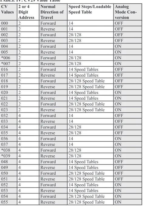
7.2.1 Characteristics Controlled by CV29
Configuration Variable 29 (CV29 for short) is a very special CV. The value entered for this CV controls several things:
1. 2 digit addressing or 4 digit addressing (as described above) 2. Normal Direction of Travel (NDOT)
3. Speed step control: Advanced Mode (28/128 speed steps) or Standard Mode (14 speed steps)
4. Analog mode conversion On or Off 5. Speed table On or Off
The Normal Direction of Travel, or NDOT for short, lets you set up your locos to run either long hood forward or short hood forward. The decoder determines which way the loco will move independent of track polarity, you can set up either direction as forward depending on the prototype.
There are two modes for speed step control: Standard or 14 speed step mode
and Advanced or 28/128 speed step control.
Because of differences in the capabilities of DCC compatible command sta-tions and decoders, you may have to set CV29 in your decoders to different values to match the mode of the command station you are using. If your com-mand station sends standard 14 speed step mode comcom-mands, your decod-ers must be programmed for standard mode. If your command station sends advanced 28/128 speed step commands, your decoders must be programmed for advanced mode. All Digitrax decoders are 128 speed step capable and we recommend that for best performance you run them in 128 speed step mode. If you are using non-Digitrax decoders that do not support advanced mode and you want to run your command station in advanced mode, you can “status edit” the standard decoders so that they can be run with your command station. See your starter set manual for the specifics of status editing.
Loadable speed tables can be enabled or disabled with CV29. Speed tables are used to customize the throttle response curve of each decoder equipped loco-motive. The speed table values can be stored in the decoder and then the table can be turned on or off with CV29. See the section on CVs 65-93 below for a complete description of how speed tables work.