Volume 5, Issue 10, October 2016
Abstract— This paper presents the position control scheme of
DC servo motor drive. The fuzzy logic controller (FLC) is developed for controlling the position of DC servo motor drive. The DC servo motors are highly preferred because of high power rating and speed of the motor. The proposed technique is a closed loop real time control scheme where the position control is obtained through position sensor, it is coupled with the motor shaft for provides a feedback position signal. The performances of the proposed fuzzy logic controller based DC servo motor drive at Flat-Bed Screen printing machine were investigated. The simulation model is demonstrated and outcomes illustrate that the FLC gives good dynamic performance and then it is preferably suited for industrial position control drive applications.
Index Terms— DC servomotor, position control system, linear,
FLC controller, MatLab.
I. INTRODUCTION
In recent years DC motors are used in high performance drive systems because of its advantages. A DC servo motor which is usually a DC motor of low power rating is used as an actuator to drive a load. It is having high ratio of starting torque to inertia and faster dynamic response. Because of their high reliability, flexibility and low cost, DC servo motors are widely used in industrial applications, robot manipulators and home appliances where speed and position control of motor are required [1]. It is a common actuator in control system, it is directly provides the rotary and transitional motion. In this paper, permanent magnet DC motor is preferred.
The field excitation is operated by permanent magnet and remains constant under all operating conditions. DC servo drive systems normally use the full four quadrant operations which allow bidirectional speed control with regenerative braking capabilities [2]. This paper demonstrates the position control based drive by conventional fuzzy controller.
The conventional methods have the following difficulties, it depends on the accuracy of the mathematical model of the system and the expected performance is not met due to the load disturbances. The classical linear control shows good performance only at one operating speeds. Fuzzy logic is a technique to embody human like thinking into a control
Manuscript received September, 2016.
Thwin Thu Lynn, Electrical Power Engineering Department, Yangon Technological University, Yangon, The Union of Myanmar, 09785048872.
Eaint Thet Kyi Phyu, Electrical Power Engineering Department, Yangon
Technological University, Yangon, The Union of Myanmar, 09254068504.
Naing Naing Maw, Electrical Power Engineering Department, Yangon
Technological University, Yangon, The Union of Myanmar, 095048872.
system [3]. Fuzzy control has been primarily applied to the control of processes through fuzzy linguistic performances. The fuzzy controller gives the better dynamic performance as well as error reduction.
In this research, the operating process of the Flat-Bed Screen printing machine at Yamathin textile factory that is located in Mandalay division is considered. After that, a complete simulation model of the positioning control of BLDC servomotor using FLC controller drive is proposed using MatLab/Simulink. With FLC, it can be reduced the occurring of disturbances and uncertainties more than the other classical methods. A FLC controller which own controller parameters are based on external disturbance and internal variation of the converter with minimum steady state error, overshoot and rise time of the output voltage.
The first section gives the introduction and importance about the paper. The second section is about the operational process of Flat-Bed Screen printing machine. The third section of the paper discuss about the DC position servo drive concept. Design of speed/position controller with conventional and fuzzy technique is discussed in the third section of the paper. The sixth section deal with the simulation carried through MATLAB environment and about the results and discussions. The final section present in this paper is the conclusions.
II.
O
PERATIONALPROCESSOFFLAT-BEDSCREENPRINTINGMACHINE
Fig.1 shows the process of the Flat-Bed Screen printing machine, it is mainly included three parts. These are the fabric carriage, making boundaries and filling ink, washing and drying machine. Firstly, fabric carriage drawn one meter of the white clothing. Secondly, it was passed through the printing processes area which makes boundaries and filling ink by driving the strokes. After that, it would be worked the processing of washing and drying on the dying clothing. This is also called the finishing part of the overall of the printing machine.
The processing of Flat-Bed Screen printing machine was mainly used to drive the two servomotors by synchronizing the balancing on the printing process area. The one is fixed on the process starting and the other is fixed on the process ending. These two included the encoder individually to get the exact positioning. Encoders were sent the control signal by passing the motion on position. This positioning signal was again sent to the controller driver which used in RS232 and RS485 signal. Moreover, these signals carry out of the
Position Control of DC Servo Drive by
Fuzzy Logic Controller in
Flat-Bed Screen Printing Machine
Thwin Thu LynnVolume 5, Issue 10, October 2016 servo amplifier used in 24Vdc. And then, finally, it would be
reached the host computer to set all of motion signals. A typical closed loop positioning system can be divided into three elements. There are position controller, servo amplifier and actuator. Position controller performs real time positional control of the motors, stores the application program and communicates with the user and other control equipments. Servo amplifier which takes demand signals from the position controller to control the torque or speed of the actuator. Actuator translates electrical power from the servo amplifier into rotary or linear movement. The motor is fitted with a position sensor which feeds the output position back to the controller [4].
Electrical motor torque is proportional to the product of magnetic flux and the armature current. Mechanical or load torque is proportional to the product of force and distance. Motor current varies in relation to the amount of load torque applied. When a motor is running in steady state, the armature current is constant, and the electrical torque is equal and opposite of the mechanical torque. When a motor is decelerating, the motor torque is less than the load torque. Conversely, when a motor is accelerating, the motor torque is higher than the load torque [5].
Fig.1 Overall diagram of processing of Flat-Bed screen printing machine
c
III. DCPOSITIONSERVODRIVE
The DC position servo drive is depicted in the Fig 2. The position and speed control is obtained with fuzzy logic controller. The block diagram consists of four quadrant chopper with bidirectional control drive which drives the dc servo motor. The supply to the 4-quadrant chopper is derived from the diode rectifier. The chopper circuit contains four MOSFET’s. The gate pulse for the MOSFET is obtained from PWM generator. MOSFET 1&2 areforward direction and 3&4 are reverse direction of the motor. So that the motor can able to run in 4-quadrants such as forward motoring, forward braking, reverse motoring, and reverse braking [3].
The block diagram shows the shaft of the motor is coupled with the position sensor. The position sensor is used to obtain the actual position of the motor. It is then compared to set position, the difference between set point and outputs generate an error. If the set position is greater than the actual position then the position error output of the comparator is positive, else it will be negative. The position error so
obtained is processed in position PI controller and its output sets the position angle then it is fed to limiter. It controls the speed range from higher to lower limited value, here the carrier and reference signal are controlled and modulated up to desired values. This PWM pulses is fed to the gate of MOSFET in the four quadrant chopper.
Fig.2 Block diagram of DC position servo drive
By varying the duty cycle of the pulses, the motor voltage can be varied. The position of the motor is obtained by indirect form of measurement by integrating the speed of the motor.
𝜃 = 𝜔𝑑𝑡 Eq (1) 𝜃𝑒 = 𝜃𝑠 − 𝜃𝑟 Eq (2)
The above equations describes θe = position error, θs = set
position, θr = actual position of the motor.
By varying the duty cycle of the chopper, the output voltage gets controlled. The output voltage of the chopper is given as,
V0 = Vdc* (Ton-Toff) / T Eq (3)
If the duty cycle is 50%, both on and off time same so the motor is not in operating condition. At same time if we increasing or decreasing the pulse width the drive will operates either in forward or reverse manner.
IV. DESIGNOFPOSITIONCONTROLLER
A. Fuzzy Logic Controller
Fig.3 Fuzzy logic controller
To determine a fuzzy rule from each input-output data pair, the first step is to find the degree of each data value in every membership region of its corresponding fuzzy domain. The variable is then assigned to the region with the maximum degree, when each new rule is generated from the input-output data pairs, a rule degree or truth is assigned to that rule, where this rule degree is defined as the degree of confidence that the rule does in fact correlate to the function relating voltage and current to angle.
Fig. 3 shows the block model of fuzzy logic controller. The position error is calculated with comparison between reference speed/position. Speed error (e) and speed error changing (ce) are fuzzy controller inputs. The input variables
Volume 5, Issue 10, October 2016 are normalized with a range of membership functions
specified.
The fuzzy logic controller initially converts the crisp error and change in error variables into fuzzy variables and then are mapped into linguistic labels. Membership functions (MFs) of input ‘e’, ‘ce’ and ‘Nm’ are shown in Fig.3 which consists of two inputs and one output. The triangular membership functions are used for all the fuzzy set of the input and output vectors. There are seven MFs for the input e,ce as rpm and output as Nm. All the MFs are symmetrical for positive and negative values of the variables. The linguistic labels are divided into seven groups.
Fig.4 Membership functions
They are NB = negative big, NM = negative medium, NS = negative small, ZE = zero, PS = positive small, PM = positive medium, PB = positive big.
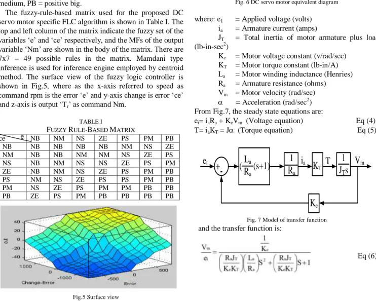
The fuzzy-rule-based matrix used for the proposed DC servo motor specific FLC algorithm is shown in Table I. The top and left column of the matrix indicate the fuzzy set of the variables ‘e’ and ‘ce’ respectively, and the MFs of the output variable ‘Nm’ are shown in the body of the matrix. There are 7x7 = 49 possible rules in the matrix. Mamdani type inference is used for inference engine employed by centroid method. The surface view of the fuzzy logic controller is shown in Fig.5, where as the x-axis referred to speed as command rpm is the error ‘e’ and y-axis change is error ‘ce’ and z-axis is output ‘Tr’ as command Nm.
TABLE I
FUZZY RULE-BASED MATRIX
NB NM NS ZE PS PM PB NB NB NB NB NB NM NS ZE NM NB NB NM NM NS ZE PS NS NB NM NS NS ZE PS PM ZE NB NM NS ZE PS PM PB PS NM NS ZE PS PS PM PB PM NS ZE PS PM PM PB PB PB ZE PS PM PB PB PB PB
Fig.5 Surface view
V. CONTROLMETHODS
A. Servomotor’s equations
In the analysis of electric servo drive motors, the equations for the motor indicate the presence of two time constants. One is a mechanical time constant and the other is an electrical time constant. Since these two time constants are part of the motor block diagram used in a servo analysis, it is important to know the real value of the time constants under actual load conditions.
The brushless dc servo motor which having a position transducer inside the motor to transmit motor shaft position to the drive amplifier for the purpose of controlling current commutation in the three phases of the motor windings.
A derivation of the motor equations and the electrical and mechanical motor time constants will be discussed for the dc brushless servo motor. Fig.6 shows the dc motor equivalent diagram [6].
Fig. 6 DC servo motor equivalent diagram
where: e1 = Applied voltage (volts)
ia = Armature current (amps)
JT = Total inertia of motor armature plus load
(lb-in-sec2)
Ke = Motor voltage constant (v/rad/sec)
KT = Motor torque constant (lb-in/A)
La = Motor winding inductance (Henries)
Ra = Armature resistance (ohms)
Vm = Motor velocity (rad/sec)
= Acceleration (rad/sec2) From Fig.7, the steady state equations are:
ei= iaRa + KeVm (Voltage equation) Eq (4) T= iaKT = J (Torque equation) Eq (5)
K
ee
iK
TV
m1
J
Ts
T
i
aL
aR
a(s+1)
(
R
1
a+
-Fig. 7 Model of transfer function
and the transfer function is:
Eq (6) e
Volume 5, Issue 10, October 2016
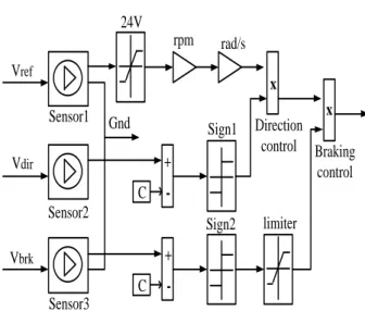
B. Speed demand controller
C C Vref Vdir Vbrk Sensor1 Sensor2 Sensor3 24V rpm rad/s Direction control Braking control Sign1 Sign2 limiter Gnd + -+ -x x
Fig. 8 Speed demand controller block diagram
Fig.8 shows the speed demand controller and the respective parameters are shown in TABLE II [5].
TABLE II
PARAMETERS OF ELECTRICAL TORQUE
Parameters Ratings
Rotational speed 3000 rpm
Maximum torque value 34 Nm
Torque control time constant 0.5e-3 Motor and drives overall efficiency (%) 50
Speed at efficiency 1200 rpm
Torque at efficiency 200 Nm
Torque independent electrical losses 13.2 e-3 Nm
Supply series resistance 2 ohm
Fig.8 shows the speed demand with FLC controller mainly classified three parts depending on the applied voltage. These are used reference voltage, directional voltage and braking voltage. Maximum reference voltage is 24V. By multiplying the directional control and braking control, it produced the reference speed demand.
Braking chopper implements a DC link between the rectifier and the inverter. It contains a DC bus integrated braking chopper. The braking resistance sets to avoid oscillation. The braking chopper which used the diode rectifier and the inverter switches parameters are specified in the converters and DC bus. Speed controller parameters are specified in the controller tab.
VI. SIMULATIONRESULTS
For system design, it is not usually necessary to model the current switching controlled by the motor driver whereas ensuring the correct torque-speed characteristics and current drawn from the DC supply. This demo shows how a system-level model of a brushless DC servomotor can be constructed and parameterized based on datasheet information. The motor and driver are modelled as a single masked subsystem.
In this example, the standard configuration is modelled whereby an inner feedback loop controls current and an outer feedback loop controls motor speed. Speed demand is set by the voltage presented at the Vref, 24V corresponding 3,000
rpm. Motor direction is controlled by the voltage presented at the Vdir pin which is set to go high after 25 seconds. Braking
is controlled by the voltage at the Vbrk which is set to go high
after 50 seconds.
The parameters shown in TABLE III represented a servomotor and driver operating torque-control mode. Data based on the assumption that torque is proportional to current that is equivalent to the driver controlling current. The motor’s permissible range of torques and speeds is defined by the manufacturer torque-speed envelope, and the output torque is assumed to track the torque reference demand with time constant. Electrical losses assumed to be the sum of a torque-independent term plus a term proportional to the square of the torque. In addition, a resistor in series with the supply included to model transmission losses between power supply and servomotor driver [5].
TABLE III
PARAMETERS OF DC SERVOMOTOR
Parameters Ratings
Nominal voltage 300V
No-load DC current to driver 44e-3 A Current loop time constant 0.5e-3
Efficiency 50% Speed 1200 rpm Rated Torque 27 Nm Stall torque 34 Nm Rotor inertia 0.3082kgm2 F ig .9 S im u la ti o n m o d e l o f b ru sh le ss D C se rv o m o to r
Volume 5, Issue 10, October 2016 In the simulation results on load condition of Flat-Bed
screen printing machine, forward direction of the rotor speed illustrates the starting processing. And then, the reverse direction of rotor speed represents the transfer function of the up and down strokes. At the stopping process, machine operates to print the fabric material.
Case 1- Load Condition
R o to r sp e e d ( rp m ) Forward Reverse Braking Electrical power (W) Second (sec) (i) Electrical power (W) E le ct ri ca l p o w er ( W ) Second (sec) (ii) Mechanical power (W)
Process1 Process2 Braking
Second (sec) M ec h an ic al p o w er ( W ) (iii) Efficiency (%) Mechanical power (W) Second (sec) E ff ic ie n c y ( % ) (iv)
Supply current (A)
S u p p ly c u rr e n t (A ) Second (sec) Mechanical power (W) (v)
Fig .10 Simulation results in load condition (i) Rotor speed (ii) Electrical power (iii) Mechanical power (iv) Efficiency (v) Supply current
At the simulation results of load condition, motor speed in rpm reaches at maximum 3000 rpm. The reversing and braking time constant have 25s and 50s respectively. Electrical powers produce to 10.5 kW as motor output. Then, the peak current reaches at 40 A at the same time. By means of the no load condition, mechanical power have no output. In the results of positioning controller, it can be changed by the processing of Flat-Bed screen printing machine. According to centroid method, the outcomes should be
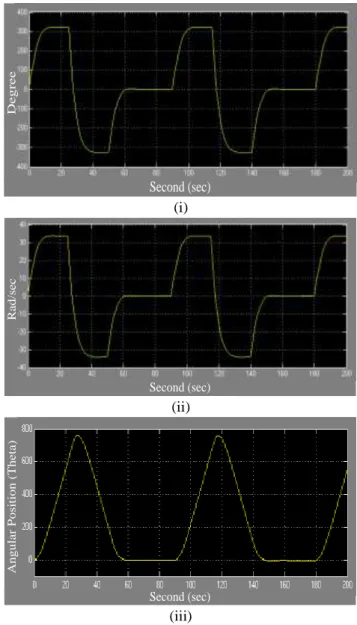
halving of input for good position control system. Likewise, the simulated outcomes of angular position obtained approximately 800 degrees as shown in Fig.11 in accordance with input 1600 degrees. As the smooth performance of the positioning controlling of Flat-Bed screen printing machine, using fuzzy logic controller is preferable in the plant.
Case 2- Position Control
D e g re e Second (sec) (i) R a d /s e c Second (sec) (ii) A n g u la r P o si ti o n ( T h e ta ) Second (sec) (iii)
Fig.11 Simulation results in positioning condition (i) Degree (ii) Radian per second (Rad/sec) (iii) Angular position (Theta)
VII. CONCLUSION
Fuzzy logic controller is applied in servomotor drive for position control used in Flat-Bed Screen printing machine in Yamathin textile factory. Simulation is carried out for the proposed control system to demonstrate the performance of servomotor drive in Flat-Bed Screen printing machine. It is demonstrated that the position of DC servomotor can be controlled and return back to desired value easily. Fuzzy logic control system is necessary to change the control parameters at any conditions. So, the best synchronising performance of the positioning with fuzzy logic controller on printing machine produced within the using load condition. Therefore, fuzzy logic controller gives good dynamic
Volume 5, Issue 10, October 2016 performance and then it is preferably suited for industrial
position control drive applications.
ACKNOWLEDGMENT
The author would like to express her heartfelt gratitude to Dr. Wunna Swe, Head of Electrical Power Engineering Department, Yangon Technological University, for his helpful suggestions and valuable ideas. The author also wishes to thank all of teachers, Electrical Power Engineering Department, Yangon Technological University, for their enthusiastic encouragements, helps and instructions. The author expresses her thankful to all persons who will concern to support in preparing this paper.
REFERENCES
[1] Ahmed, N.A.,2005, Modeling and simulation of AC-DC buck-boost converter fed dc motor with uniform PWM technique-Elect. Power syst. Res.,73: 363-372.
[2] Dewan, S.B. And Straughen, A., Power semiconductor circuits, johm Wiley & sons, New York, 1975.
[3] Chuen Chien lee, “fuzzy logic in Control systems: fuzzy logic controller-part1, 2 “ 1990 IEEE.
[4] Rajnish Mitter, Krishan Kumar, Vivek Kumar, Simulation of Fuzzy logic controller for controlling the position and speed of the DC motor, Issue 1(August 2012)
[5] NextMove BX Installation Manual Book ,MN1258 (11/98) Issue 1.02 [6] Fuzzy logic Toolbox user guide. Natick, MA: Math Works, 1997. [7] George W.Younkin, P.E. , Electric Servo Motor Equations and Time
Constants
[8] R.W. Erickson, Fundamentals of Power Electronics, 2nd ed. Secaucus,
NJ: Kluwer, 2000.
Thwin Thu Lynn , B.Tech.EP (2006), Maubin Technological University, BE.EP (2008) (Maubin Technological University), ME.EP (2011); (Mhawbi Technological University, Ph.D.EP (2016); Yangon Technological University ; Electrical Power Engineering Field;