Abstract— Good tested designing of the system maximizes
its performance and lowers the development cost. This paper focuses on the model-based test-driven development of embedded systems using modeling languages. The test driven embedded system development using modeling languages is more efficient to reduce cost of testing. Testing early in the design phase ensure that the software uses the full capability of the hardware and thus avoids the redesign of hardware. Model driven designing and test driven development using modeling languages can be used to create reliable embedded software code for safety-critical and security-critical embedded systems.
Index Terms— Embedded System, Model driven designing,
Test driven development.
I. INTRODUCTION
An embedded system is a specifically designed computing device which is used inside of a device. For example, an embedded system in a microwave oven accepts user input from the panel, manages the LCD display, and controls the heating elements of microwave. Embedded systems generally use microprocessors that contain many functions of a computer on a single device (i.e. System-on-chip). Embedded software is often integrated in highly complex devices. Medical device software, automotive software, avionics software, military software and railway software are all used to control devices or vehicles on which people's lives depend. A fault in that software may not just be inconvenient, it could be disastrous. The many of embedded software developers uses traditional programming languages such as C and C++. It uses inbuilt processes and techniques in the language to improve reliability and reduce security flaws. However, the test driven development (TDD)[2] with model driven architecture (MDA)[4] approach met with increasing success. Embedded software development methodologies historically have amended to concentrate on tools that support the embedded software developer with system configuration, integration, and particularly testing. In this paper, we try to illustrate the use of modeling languages for test driven development of embedded system. Models must
Manuscript received June, 2016.
Pravin Y. Karmore, Research Scholar, Dept. of Electronics and Computer Science, RTM Nagpur University, Nagpur, India, 9422815212.
Dr. Pradeep K. Butey, Dept. of Computer Science, Kamla Nehru College,Nagpur India, 9422110365.
be articulated in a modeling language with a properly defined grammar and semantics accomplish by expressing both static structure and dynamic behavior at an abstract level removed from the programming domain [11]. Through the Unified Modeling Language (UML) and the Systems Modeling Language (SysML) [1],[3],[7] provides a set of diagrams with semantic meaning that enable users to communicate the structure and behavior of a design.
II. RELATED WORK
A. Embedded System
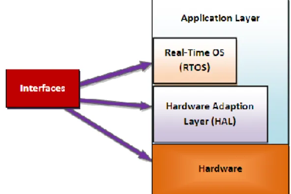
An embedded system is a specialized microcontroller based computing device used as a part of another system or machine. Normally, an embedded system is built on a single microprocessor board with the software stored in ROM. Some common examples of applications of embedded systems are telecommunications, automobiles, consumer electronics, and plant control. Even though the application domains are dissimilar from each other, they have universal organization in functional configuration. A layered embedded system structure, including application programming interfaces, hardware-dependent software, application software, and hardware platform is shown in Figure 1 [5][6]. Application program interfaces are essential for communication between the hardware-dependent software (System Software) and the application layer of software (Application programs). The hardware-dependent software is attached with the external physical hardware and network. Real-time Operating System (RTOS) and device drivers are closely attached to the hardware platform of the system. According to an application domain, performance and size are the constraints that usually influence the hardware platform. As per specific application, a processor and memory system must meet a minimum requirement.
Figure 1 Architecture of an embedded system
Test Driven Development of Model Driven
Embedded Systems
Volume 5, Issue 5, May 2016
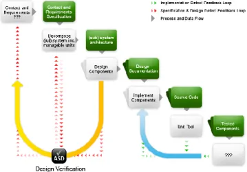
Figure 2 System-level design processes
B. Designing Embedded System
An embedded system designing includes main four steps [7]. The basic steps are the following:
Requirements specification
Hardware and software partitioning Software design
Hardware design Interface design
System integration and test
System developers can derive required functions after evaluating system requirements. These functions are considered for allocation of hardware or software. Development of hardware and software is done parallel with the interface design. After development of all required hardware and software components, they are integrated to build a system and go ahead for the testing of system. The system level design steps are shown in Figure 2.
III. OVERVIEW OF UML AND SYSML
The modeling using the Unified Modeling Language (UML) and the Systems Modeling Language (SysML) provides a rich set of diagrams with semantic meaning that allow users to communicate the structure and behavior of a design as well as maintain consistency across user views [8].
A. Unified Modeling Language
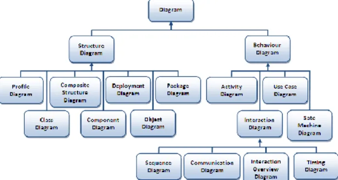
In software engineering, the Unified Modeling Language (UML) [1] has become more popular and widely used as a visual modeling language since 1997. Figure 3 depicts the different types of diagrams available with the latest version of UML. The latest version of UML allows the system developer to create 14 types of diagrams. It is divided into two main categories: structure diagram and behaviour diagram. The structural information category has seven diagram types such as profile, class, composite structure, component, deployment, object and package. The second category is for general types of behavior and used to create activity, interaction, use case and state machine diagrams. Further,
interaction category has sequence, communication, interaction overview and timing diagrams.
Figure 3The latest version of UML allows 14 types of diagrams
B. Systems Modeling Language
For additional system-engineering concepts in other modeling tools ranging from Visio to Verilog used to model and then integrated them. This will difficult in integrating as per different viewpoints and obtaining traceability, therefore the Object Management Group (OMG) decided to design UML for systems engineering. In the year 2003, a customized version of UML suitable for systems engineering to be specially made by the OMG's System Engineering Domain Special Interest Group (SE DSIG) for systems engineering was intended to support modeling of a broad range of systems, which may include data, hardware, software, procedures, personnel, and facilities. As a result of this, a consortium called SysML Partners proposed the Systems Modeling Language (SysML) [3]. Initially, many new diagrams were considered, but finally just two diagrams the Requirements Diagram and the Parametric Equations Diagram were considered.
1) Requirements Diagrams
The Requirements Diagram has an underlying requirements model. SysML states: "The requirements model illustrates the SysML support for describing textual necessities and concerning them to the specification models, analysis models, and design models. A requirement represents the behavior, structure, and/or properties that a system, component, or other model components must satisfy.” [9]
2) Parametric Equations Diagrams
Parametric Equations Diagrams are usually used to model properties and their relationships. The diagrams specify the allowable range values for complex mathematical and logical expressions as well as constraints. Generally a reference to the language is used to state the expressions and constraints.
Figure 4 Requirements diagram for vehicle
Figure 5 Parametric equations diagram for weapon and firing
The parametric model can include logical expressions, differential equations such as {when Y=7 or X<1}, or other constraints such as {Y< 3x+7}, expressed in a specific language, such as MathML or a programming language. Generally, parametric models are captured in analysis models to support performance models; feedback and control; and engineering models for safety, reliability, mass properties, and design to cost [9]. The SysML specification of a simplified model of the antilock braking system in the Car is shown in Figure 6.
IV. MODEL DRIVEN DESIGN
Model driven design (MDD) is based on the efficient use of models as a primary objective throughout the software engineering life cycle. The main objective of MDD is to provide a central role to functional models in the specification, design, integration, and validation of software. Model driven development uses models to represent a system’s elements, the structural relationships between them and their dynamic interactions and behavior. Modeling structural relationship supports design exploration and system partitioning. The modeling behavior and interactions are required to verify designs by verifying models and for code generation. But many embedded software developers hesitate to accept the generated code. The rejection of code by developers means loss of MDD advantages. Use of the MDD approach means accepting automatic code generation from models.
Figure 6 SysML specifications for antilock breaking system in the Car
A properly defined grammar and semantics models is capable of expressing both static structure and dynamic behavior. Such type of models at an abstract level differentiated from the programming domain must be articulated in a modeling language. These languages divided into two groups:
A. Vendor-specific language – It is developed and promoted
by a specific vendor of an MDD platform such as Esterel from Esterel Technologies, MatLab and Simulink from MathWorks, and the ASD language used in Verum Software Technologies’ Analytical Software Design (ASD): Suite [10] (see Figure 7 below). ASD Suite allows the system developer to create an initial set of requirements. There is no requirement of coding, testing, and refining each component in separate steps. In view of this, the modeling tool identifies both the external and internal performance of the elements using its two basic model types: interface models and design models.
B. Standardized languages – A group of interested industry
users and MDD platform vendors defined languages, which are most commonly based on the Unified Modeling Language (UML).
Figure 7 ASD: Suit Model Driven Design [10]
V. TEST DRIVEN DEVELOPMENT
Test driven development (TDD) provides various advantages over the traditional software development/test cycle. The test driven development using modeling provides the developer to create an initial set of requirements. In TDD, a developer finds out ways to build the system testable,
Volume 5, Issue 5, May 2016
designs as per the specifications, writes tests and builds, testing strategies, and then writes the functional code to meet the specified requirements of the test-spawned design [12] [13].
Advantages of TDD in embedded software:
1. The code is always tested. Testing drives the design of the code. The code is improved because of the decoupling required to create testable code.
2. The system grows organically as more knowledge of the system is gained. The tests are "living" documentation, because the knowledge is gained in tests.
3. The developers can alter existing code or add new features with confidence because automated regression testing will reveal failures and unexpected results. 4. Because of the inconsistency of hardware and software
during development, bugs are due to software, hardware, or a combination of the two.
5. The software bugs can be removed to such an extent that it becomes easier to locate, by method of elimination, the cause of the unexpected system.
VI. TESTING OF MODEL DRIVEN DESIGN
Using MDD, we can eliminate specification and design errors early in the development cycle where they are cheapest and easiest to rectify. It helps to increase the degree of automation that can be applied to the development process by means of automatic code generation. The test driven development of MDD facilitate parallel hardware/software design by enabling system models to be tested using a simulated execution mechanism on development hosts before the target system is available (see figure 8) [13]. Such a development reduces the required testing effort by applying automated formal verification methods to the functional models in collaboration with simulating execution behavior instead of relying solely on testing the implemented program code [12].
A. Executable models
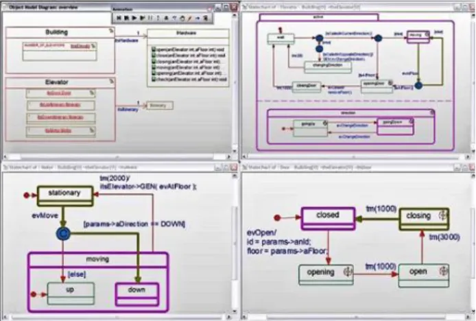
The MDD leads to design system rigorous and precise enough to allow for code generation and test case generation, in addition, executable models can be executed on the development system by means of simulation very early in the development life cycle. Executable model provides the rapid and early feedback on specifications and requirements that are tested with the actual requirements of the system. It allows functional testing to perform on the development host design without accessing software running on the target machine. This is very important in case of parallel development of hardware and software development. There are two popular platforms are available, IBM’s Rational Rhapsody and Graphics Bridge Point. Both use UML-based modeling languages. The model can be “generated” into code for the model-driven design which would run on an embedded target. Using the high end tools, such as IBM Rational Rhapsody, the structure and behavior of the complete model-driven design can be automatically created (see figure 9). The model execution with Rational Rhapsody enables early design validation when bugs are less costly to fix.
B. Scalability
The symbolical testing in early design phase examines the overall state space of an embedded software design to identify whether or not the particular properties hold under all possible inputs. There are different approaches to for different model driven design platforms.
Figure 8 Model driven testing of embedded system
Figure 9 Model execution with IBM Rational Rhapsody
Some MDD platforms limit the class of designs that can be tested. For example, SCADE Suite of Esterel Technologies deals with synchronous, deterministic designs. A compositional verification approach by ASD of Verum Software Technologies provides verification of entire system component by component to prove the properties still hold when the components are integrated to form the complete system (see figure 9). Using this approach completely concurrent and asynchronous design was properly tested for compliance with the specified properties. It also describes the absence of typical asynchronous and concurrent design bugs such as race conditions, live locks and deadlocks. Simulation and testing are normally useless at reducing such errors.
The MDD platforms widely used in the safety, security and mission-critical domains such as rail transportation, aerospace, automotive and military applications is gradually increasing. If an MDD platform is used with sufficient verification and testing facilities on design models, the unit testing requirement can be reduced. The MDD standards differentiate between the operational embedded software changed as part of the system from the modeling tools used to build that software. The different standards for safety-critical embedded software often needs the tool users to carry out an evaluation of the tool to classify it according to whether or not the tool itself can introduce errors into the operational embedded software and to perform an evaluation of the tool against the appropriate criteria for safe and secure use.
VII. CONCLUSION
Model driven design is an important system development technique worth considering for embedded systems that have safety, security, and/or reliability requirements. Test driven approach to model driven design of embedded system has potential development cost and time efficiencies and ability to reduce the occurrence of software design flaws. The consideration of the most appropriate MDD platform for a particular component and for the overall system requires that developers understand the major technical advantages and disadvantages of available tools. The test driven embedded system development using modeling languages is more efficient to reduce cost of testing. Testing early in the design phase ensure that the software uses the full capability of the hardware and thus avoids the redesign of hardware. The development of universal tool that can be used to model and generate software code for all the needs of embedded system development is the future work. The reliability is the major issue for the development of safety-critical and security-critical embedded system software development. The care should be taken while selecting the tool for the designing of such a system. In general, test driven models that are developed using modeling language tools works as a right path for the specified target.
REFRENCES
[1] Object Management Group. OMG Unified Modeling Language (OMG UML), Infrastructure, Version 2.4.1; August 2011.www.sysml.org. [2] Michael J. Karlesky, William I. Bereza, and Carl B. Erickson, Effective
Test Driven Development for Embedded Software, Ph.D. Thesis. [3] SysML Object Management Group (OMG), 2003. UMLTM for Systems
Engineering Request For Proposal OMG Document: ad/03-03-41. [4] Pravin Karmore and Pradeep Butey, Analysis of Model-based Testing
Methodology for Embedded Systems, International Journal of Advanced Research in Computer Science and Software Engineering, Volume 6, Issue 5, P.P 308-314, May 2016.
[5] Alberto Sangiovanni-Vincentelli and Grant Martin, “Platform-Based Design and Software Design Methodology for Embedded Systems,” IEEE Design & Test of Computers, November-December, 2001, pp.23-33. [6] M. Sgroi, L. Lavagno, and A. SangiovanniVincentelli, “Formal Models
for Embedded Systems Design,” IEEE Design & Test of Computers, April-June, 2000, pp.2-15.
[7] Byeongdo Kang, Young-Jik Kwon, Roger Y. Lee, “A Design and Test Technique for Embedded Software”, Proceedings of the 2005 Third ACIS IEEE Int'l Conference on Software Engineering Research, Management and Applications (SERA’05), 2005.
[8] Matthew Hause, Francis Thom, and Alan Moore, “An overview of Systems Modeling Language”, December 2005.
[9] Mellor SJ, Balcer MJ. Executable UML, A Foundation for Model-Driven Architecture. Reading, MA, Addison-Wesley; 2002.
[10] Guy Broadfoot,Using model-driven development to reduce system
software security vulnerabilities, Verum Software Technologies, March
2014.
[11] Padma Iyenghar, ElkePulvermueller and Clemens Westerkamp, “Towards Model-Based Test Automation for Embedded Systems Using UML and UTP”, IEEE, ITFA, 2011.
[12] Deepak A. Mathaikutty, SumitAhuja and AjitDingankar, “Model-driven Test Generation for System Level Validation”. IEEE, 1-4244-1480, 2007.
[13] David Astels, Test Driven Development: A Practical Guide, Upper Saddle River, NJ: Prentice Hall PTR, 2003.
Authors Profile
Pravin Y. Karmore pursuing Ph.D. in Computer Science from RTM Nagpur University, Nagpur. He is obtained Master in Computer Applications degree from RTM Nagpur University, Nagpur. And M.Phil. degree in Computer Science from Alagappa University, Karaikudi. At present he is working as Assistant Professor at Dept. of Computer Applications, Shri Ramdeobaba College of
Engineering and Management, Nagpur. His research area is Software Engineering, Embedded Systems and Neural Networks.
Dr. Padeep K. Butey obtained M.Sc. degree and
PGDCS&A from RTM Nagpur University, Nagpur. He obtained his Ph.D. degree in Computer Science from RTM Nagpur University, Nagpur. Now he is working as Associate Professor and Head at Dept. of Computer Science, Kamla Nehru College, Nagpur. He has published more than 35 research papers in various national and international conferences and journals.