288 All Rights Reserved © 2017 IJSETR
Enhancement of Transient Stability with Unified
Power Flow Controller-UPFC
Poonam G Umap Assist. Prof Prashant P Jagtap
Dеpartmеnt of ЕlеctricalЕnginееring Dеpartmеnt of Еlеctrical Robotics G H Raisonicollеgе of Еnginееring
RTMNU Nagpur Univеrsity
G H Raisonicollеgе of Еnginееring RTMNU Nagpur Univеrsity
ABSTRACT
UPFC is a Flexible AC Transmission System devicewhose role is controlling the flow of power in transmission line thus improving the system stability. The configuration of power system includes three generators, three transformers,
nine buses, four loads and
UPFC. The UPFC along with POD controller helps in enhancing the dynamic performance of the system. UPFC-POD along with fuzzy logic helps in damping the oscillation in the system. Therefore in this paper, a hybrid combination including fuzzy with UPFC and POD control strategy is proposed to damp the oscillation. Simulation is done using Matlab/Simulink software and results are shown with and without hybrid controller. The fault is preparedto occur near generator for 200ms.
KEYWORDS:FACTs, PID, POD, Power System,
Controller, UPFC model
I INTRODUCTION
These days the power generation and transmission has been limited severely due to the limited available sources and environmental restrictions. So to overcome the above issue FACTS play a major role [1][2].Of many FACTS devices, UPFC is the most flexible device and is multifunctional. The power system stabilizer (PSS) were in use for damping oscillations in power system, but could not produce enough damping to inter-area mode, thus FACTS like STATCOM and UPFC came into existence [3][5]. In this paper, UPFC along with fuzzy coordination scheme is utilized to damp oscillations in the system [4].Gyugi proposed UPFC [6]which is an effective controllerto control and optimize flow of power in transmission line[7]. The UPFC is formed by the combination of STATCOM and SSSC, connected by a common DC link [8][9].
To ensure secured system operation, it is always necessary to damp the electromechanical oscillation in the power system. [10]Gives many methods for damping oscillations in
single and multi-machine infinite bus systems using flexible ac transmission system devices. But great results are obtained, when used the concepts of fuzzy logic, neural networks and genetic algorithms [11][12]. In this paper fuzzy based UPFC was used.
Fuzzy control with linguistic information has several advantages like model-free, robustness, universal approximation theorem and rule based algorithm [7][13]. Fuzzy controller are rule based controllers, contains set of rules representing control decision mechanism. FLC’s do not need any mathematical mode and can handle huge range of operating conditions. UPFC with fuzzy logic can eventuallylessen the power oscillation damping in multi-machine systems [14].
The paper is ordered as, Introduction to FACTS, UPFC and FLC was presented in previous paragraphs. Section 2 gives the modeling of 3-machine 9-bus system model. The control strategy containing UPFC and FLC was discussed in Section 3. Section 4presents the simulation results; finally Section 5 gives the conclusion of the paper.
II. 3-MACHINE, 9-BUS SYSTEM MODEL
In this paper, the system model is developed containing three generators, four loads and nine buses. The models are developed without and with controllers as shown in Figs 1 and 2 respectively. The generator 1 is connected to the bus 1, generator 2 to bus 8 and generator 3 to bus 5. The transformers 1, 2 and 3 are placed near the generator buses for transmitting power either by stepping up or stepping down. As the power system is nonlinear in nature, there is a requirement of mathematical model for modeling and simulating in Matlab/Simulink software. After the process of linearization the total system model is in state space form as
Δx = AΔx + BΔu
289 All Rights Reserved © 2017 IJSETR
Fig. 1: A systemmodel without the controllers
Here, ∆x,∆y, ∆uindicates state vector, output vector and input vectorwith lengths as n, m and r respectively. A is system state matrix, B is control input vector, C is control input vector and D is feed forward matrix whose sizes are (nxn), (nxr), (mxn) and (mxr) respectively. The Table I gives the simulation parameters of the system.
TABLE I
In the linearized system model, the controller was kept in loop along with the plant model, such that when any disturbance like fault occurs the oscillations are damped quickly within no time [12]. Therefore this system is considered as the closed loop feed control system.
Fig. 2 : A systemmodel with POD-UPFC & the fuzzy controller In this system model, controllers are placed in a loop; such that when any disturbances like faults occur, the oscillations are damped quickly with in no time [12].
III CONTROL SCHEME
A controller controls the entire system and provides stability of the system at all the times i.e., even during the fault or disturbance or noise. A UPFC is a FACTS devicemostly used in compensating reactive power on transmission network of high voltage. It also regulates magnitude of the voltage, phase angle, line impedance and controls the flow of active and reactive power in transmission line [5]. It also improves steady state and dynamic performance of a system, giving better system stability and voltage control. Furthermore when coordinated with damping controller, the UPFC can further improves the power system performance dynamically.
UPFC is a FACTS device mostly used for reactive power compensation in transmission networks. Fig. 3 shows the block diagram in which 2 voltage source converters(VSC) are presented linked through a common DC link capacitor. There are two transformers in the figure namely boosting transformer and excitation transformer, coupled together by the two converters. One transformer is connected I series and other in shunt to the line. The converters compensate active and reactive power. Whereas the UPFC not only controls the flow of active and reactive power in steady state conditions but also improves the damping of system oscillations by converter voltage modulation.
290 All Rights Reserved © 2017 IJSETR
Conventionally FACTS along with PODcontroller andUPFC were in use, in which the settling time, oscillations and ringing effects of different power system parameters may be more. These can be reduced by the usage of POD and UPFC to coordinate with fuzzy controller. And to obtain more accurate results, POD based UPFC scheme is coordinated with a fuzzy scheme, which is used in this work. The fuzzy controller has lot of merits compared to conventional (POD-UPFC) and classical (P,PI,PID) controllers like simplicity, low cost, high reliability etc. Fig 4 shows the Fuzzy Logic Controller along with POD-UPFC for power oscillation damping.
Fig. 4: A diagrammatic view of fuzzy logiccontroller along with POD-UPFC
In single machine systems, the issues can be solved by POD along with UPFC controllers, but in multi-machine systems, there may be occurrence of large disturbances and faults. In such cases to obtain best coordination among different parameters of POD-UPFC, fuzzy logics play an important role together with POD-UPFC controller in providing the best performance of the system. The advantage of fuzzy controller over classical (P, PI, PID) and conventional (POD-UPFC) are simplicity, low cost, highly reliable, hardware compactness and no requirement of mathematical model in designing.
Fuzzy logic contains linguistic variables, represented by fuzzy sets. In fuzzy sets, an element can partially belong to one or more sets. A fuzzy logic controller works based on fuzzy rules, expressed in conditional statements form. The basic structure that damps out power system oscillations comprises of 3 parts such as fuzzification, knowledge base and defuzzification.
The rule based and data based units are the inputs to the inference system. The crisp data is converted into linguistic variables by the fuzzy unit. The knowledge base takes decision on the linguistic variables by using logical linguistic rules of rule base and relevant data of data base [8][5]. The output is forwarded as input to the next unit i.e., defuzzification unit where the linguistic variables are once more converted into numeric data in crisp form [5] using methods such as center of gravity method, center of singleton method and so on. The Table II shows the rule base used by the decision making unit.
TABLE II
The fuzzy coordination unit’s output is sent to the POD (Power Oscillation Damping), which is further sent as input to UPFC controller. The POD uses 5 blocks namely amplification block, washout link, 2-stage of lag lead blocks and a limiter.The fuzzy-POD-UPFC finally generates a control signal which is supplied to the multi machine model for damping oscillations. As the fuzzy coordination unit is kept before UPFC-POD, the amplification part of the converter controller is modified by the fuzzy; therefore the power system stability is increased.
IV SIMULATION RESULTS
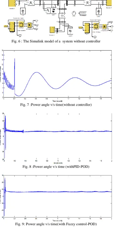
Figs. 5 and 6 show the Simulink models of a system containing 3 machines, 9 buses with Fuzzy-POD and without controller respectively, in which a line of 220kV and generators of 100MW are used. The simulation is done using Matlab/Simulink software. A fault was happened to occur at the first generator for 200ms and is simulated. The simulation results were observed for without controller, with PID-POD and with Fuzzy-POD. Figs 7-9 show the curves of power angle measured in degrees against time without, with PID-POD, and with Fuzzy-POD respectively. From the results it is shown that the power system with Fuzzy-POD controller gives the improved dynamic performance compared to the one with PID-POD and without controller.
Fig. 5 : The Simulink model system with Fuzzy-POD-UPFC Also the overshoots and undershoots exhibited by power angle curves is very less when fuzzy controller is used. The damping of power system oscillations was done within short time and reach final steady state value.
291 All Rights Reserved © 2017 IJSETR
Fig. 6 : The Simulink model of a system without controller
Fig. 7 :Power angle v/s time(without controller)
Fig. 8 :Power angle v/s time (withPID-POD)
Fig. 9: Power angle v/s time(with Fuzzy control-POD)
V CONCLUSION
In this paper, a system was developed containing three generators, nine buses without and with controller i.e., Fuzzy-POD. The power system stability was greatly improved by the Fuzzy-POD compared to the conventional controller; this is because the fuzzy coordination unit modified the amplification part of the existing controller. The simulation was done using Matlab/Simulink software with and without controller for damping power system oscillations. The simulation results were shown for power angle versus time without controller, with PID-POD and with Fuzzy-POD. From which the efficacy of the developed method is demonstrated and Fuzzy-POD was proved to be the best control method in damping the power system oscillations.
NOMENCLATURE UPFC Unified Power Flow Controller FACTS Flexible AC Transmission System
POD Power Oscillation Damping
PSOC Power System Operation & Control IEEE Institute of Electrical & Electronics
SVC Static Var Compensator
TCSC Thyristor Controlled Series Compensator TCPS Thyristor Controlled Phase Shifter SSSC Static Synchronous Series Compensator STATCOM Static Synchronous Compensator
DC Direct Current
AC Alternating Current
FLC Fuzzy Logic Control
PD Proportional Derivative
PID Proportional Integrator Derivative REFERENCES
[1] Y.-H. Song, A.T. Johns (Eds),” Flexible A.C. TransmissionSystems (FACTS)” IET, 1999, Chapter 7,Pages 1-72.
[2] Hingorani N G, GyugyiL(2000). Understanding FACTS, IEEEPress, pp., 323-387.
[3] Z. Huaang, Y.X. Ni, C. M. She, F. F. Wu, S. Chen, and B.Zhang,“Application of Unified Power Flaw controller in interconnectedPower Systems modeling, interface, control, strategy, and casestudy”, IEEE Trans. On Power Systems. Vol.15, No.2, pp. 817-824, May 2000. [4] L. Gyugi, “Unified Power flow concept forflexible AC
transmission systems”, IEEProc., Vol. 139, No. 4, pp. 323–332, 1992.
[5] M. Noroozian, L. Angquist, M. Ghandari, andG. Anderson, “Use of UPFC for optimalpower flow control”, IEEE Trans. on PowerSystems, Vol. 12, No. 4, pp. 1629–1634,1997.
[6] Narain G. Hingorani, Laszlo Gyugyi“Understanding FACTS: ConceptsandTechnology of Flexible AC TransmissionSystems”, Power electronics sponsored
byEngineers, Inc. 3 Park Avenue, New York,NY
10016-5997, 2000.
[7] V.K.Chandrakar, A.G.Kothari, “RBFN BasedUPFC for Improving transient stabilityPerformance”, WSEAS
Transactions onPower Systems, Issue 1 , Vol. 2 , pp.1-6
,Jan2007.
[8] R.P Kalyani, G.K. Venayagamoorthy, M.Crow, “Neuroidentification of systemparameters for the shunt & series branchcontrol of UPFC”, Power EngineeringSociety General Meeting, 2003, IEEE Vol.
4,13-17 Jul. 2003.
[9] S. Kannan, S. Jayaram, M. M. A. Salama,“Real and Reactive Power Coordination for aUnified Power Flow Controller”, IEEETransactions on Power Systems, Vol. 19,Issue 3, pp. 1454 – 1461, 2004.
[10] S.N. Dhurvey and V.K. Chandrakar:“Performance Comparsion of UPFC inCoordination with Optimized POD and PSSOn Damping of Power System Oscillations”,WSEAS Transactions on Power Systems,Issue 5 , Vol. 3 , pp. 287-299, May 2008.
292 All Rights Reserved © 2017 IJSETR
[11] LijunCai, IstvanErlich, “Fuzzy coordinationof FACTS controllers for damping powersystem oscillations”, Proc. Of the Int. Symp.On Modern Electronic Power Systems,Wroclaw, pp. 251-256, Sept. 11-13, 2002. [12] P. K. Dash, S. Mishra, and G. Panda,“Damping
Multi-modal Power SystemOscillation Using a Hybrid Fuzzy Controllerfor Series Connected FACTS Devices”,
IEEETrans. on Power Systems, Vol. 15, No. 4,
pp.1360–1366, Nov. 2000.
[13] K.R. Padiyar , K. Uma Rao, “Modeling andControl of UPFC for Transient Stability”,Elsevier Journal of
Electrical Power EnergySystems, N0. 21, pp. 1- 11,
1999.
[14] H.F. Wang, M. Jazaeri, Y.J. Cao, “Operatingmodes and control interaction analysis ofunified power flow controllers”, IEE Proc.,Gener. Transm. Distrib., Vol. 152, Issue 2,pp. 264–270, Mar. 2005.
[15] Gyugyi, L., “Unified power flow controllerconcept for flexible AC transmissionsystems”, IEE Proc. Gener.