Abstract—In many communication systems, information
carrying symbols are transmitted in blocks with guard intervals between blocks for avoiding inter-block interference. This paper proposes a block transmission system that can be decomposed into a set of parallel subblock transmission systems having additive white Gaussian noise (AWGN) channels with equal noise powers even when the channel additive noise is non-Gaussian. The block transmission system has the advantages that standard signal design, block codes, and symbol detection methods for an AWGN channel are easily incorporated into the block transmission system and that the system is easily implemented by FFT processors.
Index Terms—Block transmission, OFDM, spread spectrum
communication, multiplexing, channel equalization.
I. INTRODUCTION
In many communication systems, symbols are transmitted in blocks or frames. Digital audio broadcasting employs block-wise processing such as block coding that may include a filter bank or a lapped transform to improve coding efficiency [1]. One of the most important block transmission systems is the orthogonal frequency division multiplexing (OFDM). In OFDM, information carrying symbols are multiplexed using the inverse discrete Fourier transform (IDFT) at the transmitter, and recovers the symbols using the discrete Fourier transform (DFT) at the receiver. When there is a frequency-selective fading in the channel, reliable detection of symbols carried by the faded subcarriers becomes difficult because the system splits the frequency-selective spectrum into a large number of independent narrowband flat sub-channels. In order to overcome this difficulty, spreading techniques are incorporated into the OFDM system such as the complex-field coding [2], Hadamard or Fourier type transform methods [3], and short block transform methods [4].
This paper proposes a new block transmission system in which information carrying symbols are grouped into a number of subblocks. At a transmitter, these subblocks are multiplexed into a single sequence which is then transmitted. At a receiver, an equalizer is applied, and then the transmitted symbols are recovered by the demultiplexer which performs the reverse of the multiplexer. The multicarrier residue
Manuscript received October 4, 2012; revised January 10, 2013. H. Murakami is with the Kanazawa Institute of Technology, Nonoichi, Ishikawa 921-8501 Japan (e-mail: hmurk3@ gmail.com).
division multiplexing (MC-RDM) in [5] is used as the multiplexer because it has the property that information of each subblock symbol is dispersed among transmitting symbols with respect time as well as frequency.
The proposed system has the property that, even when there is a frequency-selective fading in the channel, subblock noise symbols due to an additive noise on the propagation channel become uncorrelated Gaussian random variables with same variances for a wide range of additive noise types. In other words, the block transmission system is decomposed into a set of additive white Gaussian noise (AWGN) channel systems with equal noise powers
II. BLOCK TRANSMISSION SYSTEM
The baseband model of the proposing block transmission system is depicted in Fig. 1. The system transmits N=KM
symbols in one block that are grouped into M subblocks
Xm=[Xm(0) Xm(1) … Xm(K-1)], 0mM-1, of length K.
According to MC-RDM in [5], these subblocks are multiplexed into a single N-length transmitting sequence x(n), 0≤n≤N-1, which is obtained by
, ) ( 1
) (
1
0
/ 2
K
k
K ki j m k e
X K m iM
x
(1) The K-length sequences [x(m) x(M+m) …x((K-1)M+m)], 0mM-1, are called polyphase components of the sequence
x(n), 0nN-1. The above equations say that the polyphase components are computed by K-point IFFT processors as shown in the figure. The polyphase components are composed into the single sequence x(n) at the box indicated by Poly. Com.
Fig. 1. The proposed baseband block transmission.
The discrete-time version of baseband distortion from the transmitted sequence to the received sequence is represented
A Block Transmission Method for Converting a
Non-Gaussian Channel into Parallel Gaussian Noise
Channels
Hideo Murakami
:
K- IFFT
X0
Poly. Com.
K- IFFT
K- IFFT
X1
x(n)
h(n)
K- FFT
Poly. Dec. K-
FFT
K- FFT
Y0
Y1
YM-1
y(n)
g(n) (n)
Channel Equalizer r(n)
Receiver Transmitter
:
: :
by the channel impulse response h(n), and the channel additive noise (n). We assume that interblock interference is avoided by placing a guard interval before transmitting the next block, the guard interval greater than the length of the channel impulse response.
The received sequence at the receiver is denoted as r(n). An equalizer whose impulse response is denoted as g(n) is applied to the received sequence in order to cancel the effect of the channel impulse response. The equalizer output sequence y(n), 0nN-1, is decomposed into its polyphase components [y(m) y(M+m) …y((K-1)M+m)], 0mM-1. The subblock symbols are recovered by taking the K-point FFTs of the polyphase components as
, )
( 1 ) (
1
0
/ 2
K
i
K ki j
m yiM me
K k
Y
(2) Clearly, if the equalizer output is equal to the transmitted sequence, that is, y(n)=x(n), the recovered subblocks
Ym=[Ym(0) Ym(1) … Ym(K-1)], 0mM-1, coincide with the
transmitted subblocks.
III. NOISE ANALYSIS
We assume that the channel additive noise samples (n) and (n’) are statistically independent when nn’, and that
the noise is zero-mean with the variance 2=E{|(n)|2},
where E{•} denotes the expected value. The noise may be
non-Gaussian such as impulsive noise.
If the length of the equalizer impulse response g(n) is denoted as Lg, the equalizer output noise (n) is given by
1
0
) ( ) ( ) (
g L
m
m n m g
n
(3) The variance of the equalizer output noise is then given by
1
0 2 2
2 2
) ( )
(
g L
m
m g n
E
(4) This variance is independent of the time index n.
According to (2), the subblock noise m(k) contained in
the recovered subblock symbol Ym(k) is given by
1
0
/ 2
) ( 1 ) (
K
i
K ki j
m iM me
K
k
(5) Each subblock noise symbol is given as a linear sum of equalizer output noise symbols separated by M-1 samples. Equation (3) says that, if MLg, the noise samples (iM+m),
0iK-1, are mutually independent. Therefore, if MLg, each
of the subblock noise symbol is given as a sum of K
statistically independent random variables.
The above property is clearly different from the case of OFDM, in which the receiver takes DFT of consecutive samples. The central-limit theorem says that a sum of
statistically independent random variables of fairly general statistical types approaches a Gaussian random variable as the number of sum increases [6]. When MLg, we have
( ) *( ')
2 ( ')k k k
k
Em m (6)
The above arguments are summarized in the following property.
Property: Suppose that the channel additive noise (n) and (n’) are zero-mean independent for nn’. If the number M of the subblocks is greater than or equal to the equalizer impulse response length Lg, then the subblock noise symbols m(k), 0kK-1, approaches zero-mean uncorrelated
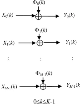
Gaussian random variables with the same variances as the subblock length K increases for fairly general propagation additive noise types. Accordingly, the block transmission in Fig. 1 is viewed as the parallel transmission system shown in Fig. 2.
Fig. 2. Equivalent parallel transmission model. m (k) are zero-mean uncorrelated Gaussian noise with the same powers.
IV. EQUALIZER DESIGN
As seen in the property of the previous section, it is desirable to design the equalizer such that the impulse response length Lg is as short as possible while keeping its
ability to cancel the distortion due to the channel impulse response.
Let h (n), 0≤n≤Lh-1, be the channel impulse response
where Lh denote the length, and introduce the (Lh+Lg-1)×Lg
matrix H defined by
(0)
0
0
(0)
(
1)
0
0
(
1)
0
0
(
1)
A
A
A
h
h
h L
H
h L
h L
(7)
The equalizer impulse response is represented in the vector
: X0(k)
X1(k)
Y0(k)
Y1(k)
YM-1(k)
0(k)
:
XM-1(k)
0kK-1
1(k)
M-1(k)
as g= [g (0) g (1) … g (Lg-1)] T. We may design the equalizer
by finding the vector g that minimizes 2
u g
H
D
(8) In this equaltion, u is the (Lh+Lg-1)-dimensional column
vector having one at the [Lg/2]th place and zeros in all the
other entries, where [Lg/2] denotes the integral part of Lg/2.
Then the equalizer output will yields the approximate to the [Lg/2]-unit times delayed version of the transmitted sequence.
Calculation shows that the vector ĝ that minimizes D is obtained as
*] 2 / [ 1 *
ˆ H H HLg g
(9) where H[Lg/2] is the [Lg/2]th low vector of the matrix H. Let
2 min Hˆ u
D g
(10) This value indicates the performance of the equalizer when the length of the equalizer impulse response is Lg.
Example 1: We demonstrate the equalizer design using
Rayleigh distributed channels, having complex zero-mean Gaussian taps with exponential power profile
nhc
n h
E ( )2 2
(11) where h2 and c are real constants with 0<c<1. This type of
channel models is widely used for simulations [7]-[9]. For creating the matrix H, the channel impulse response length Lh
is decided as the smallest integer n such that cn<10-5. Channel impulse responses are created according to Monte Carlo trials, and Dmin is estimated by the numerical average of 200 trials. The average of Dmin is ploted as a function of Lg in Fig. 3 for
c=0.4, 0.6, and 0.8. Dmin rapidly decreases as Lg increases,
and can be made sufficiently small if Lg≥32. For this choice
of Lg, it is sufficient to choose M=32 in order to make (iM+m), 0≤i≤K-1, are mutually independent.
5 10 15 20 25 30 35 40 0
0.002 0.004 0.006 0.008 0.01 0.012
Lg
Fig. 3. Dmin as a function of the length Lg of the equalizer impulse response.
V. IMPULSIVE NOISE ANALYSIS
Non-Gaussian noise that appears frequently in practice is impulsive noise. When the propagation channel is
contaminated by such noise, an OFDM system performs better than a single carrier system because of its time-diversity [10]. The performance can be further improved by estimating impulsive noise terms on a frequency domain and subtracting them from the equalizer output [11], or by incorporating error-correcting-type codes for canceling impulsive noise [12]. However, when there is a frequency-selective fading in the channel, reliable detection of symbols carried by the faded subcarriers becomes difficult. In order to overcome this difficulty, spreading techniques are incorporated into the OFDM system such as the complex-field coding [2], Hadamard or Fourier type transform methods [3], and short block transform methods [4].
Since the statistic of the channel additive noise (n) is assumed to be independent of n, the impulsive noise model is, ignoring dependency on n for notational simplicity, represented as
(n)
(12) where and are zero-mean white Gaussian noise processes with variances 2 and 2, respectively, such that 2 is
much greater than 2, and is a random variable that is either zero or one [10], [12]. The probability of =1 is denoted by p. The variance of is then given by
2=E{||2}=2+p2.
The probability density function (PDF) of the complex Gaussian random variable is written as [13]
2
2
2exp
1 ) (
f
(13) The PDF of the second term in is given by
2
2
2 exp
1 1
) (
p p
f R I
(14) where =R+jI, and (R) is the Dirac delta function.
The characteristic function of is given as
4 exp exp
) (
2 2
E j R R I I
(15) In this equation, R and I represent the real and imaginary
parts of, respectively. This notational convention is applied for other variables as well. By (14), the characteristic function of is given by
4 exp 1
) (
2 2
p p (16)
Since and are mutually independent, the characteristic ——— : c=0.4
function of the channel noise is given as the product of the characteristic functions of and which is
4 exp 1 4 exp ) ( 2 2 2 2
p p
(17) This channel noise is fed into the equalizer.
According to (3), the equalizer output noise (n) is the sum of g(m)(n-m), 0≤m≤Lg-1. Since the statistic of the channel
noise (n-m) is independent of n-m, the channel noise is represented as n-m)=R+jI. Then the real and the
imaginary parts of g(m)(n-m) are given by gR(m)R-gI(m)I,
and gR(m)I+gI(m)R, respectively. The characteristic
function of g(m)(n-m) is computed as
( )( ) *( ) )
(m nm g m
g
(18) Since g(m)(n-m), 0≤m≤Lg-1, are statistically independent,
the characteristic function of (n) is obtained as the product of these characteristic functions which is given by
1 0 * 1 0 ) ( ) ( ( ) ) ( g g L m L m m n mg g m
(19) By (4) and 2=E{||2}=2+p2, the variance of is given as
0 5 10 15 20 25 30 35 40 0 0.1 0.2 0.3 0.4 0.5 0.6 0.7 K
Fig. 4. Square difference (SD) as a function of K.
0 100 200 300 400 500 600 700 800 900 1000 -1
-0.5 0 0.5
1 Channel Noise
0 100 200 300 400 500 600 700 800 900 1000 -1
-0.5 0 0.5
1 Subblock Noise
Fig. 5. Real parts of typical channel noise (n) and subblock noise m(k) when 2=0.001, 2=0.1, p=0.01, and M=K=32.
1 0 2 2 22 ( )
g L
m
m g p
(20) The subblock noise symbol m(k) is a linear sum of (nM+m)/(K1/2), 0≤n≤K-1, according to (19). We assume that
M is large enough so that (nM+m) /(K1/2), 0≤n≤K-1, are independent. Then the characteristic function of m(k) is
given by [6]
K L m K g K m g K
1 0 *( ) ) ( (21) As K increases, this characteristic function should approach the characteristic function for a Gaussian random variable with the variance 2 because the variances of and are equal by (6).
Example 2: The channel impulse response model in
Example 1 is used for this example as well. The equalizer is designed by assigning its impulse response length to be
Lg=32 which is sufficiently long to cancel the effect of the
linear distortion due to the channel impulse response as seen by Fig. 2. For this equalizer, if M≥32, (nM+m) /(K1/2), 0≤n≤K-1, are independent.
The impulsive noise is created using parameters:
2=0.001, 2=0.1, and p=0.01. The difference between
() and the characteristic function of a Gaussian random variable with the variance 2 is measured by the square difference (SD),
d SD 2 2 2 4 exp (22) Numerical averages of SDs are plotted in Fig. 4 as a function of K when the profile decaying constants for the channel impulse response are c=0.4, 0.6, and 0.8. The characteristic function is sufficiently close to the characteristic function for a Gaussian random variable by choosing K≥32. Combining with the condition M≥32, thecondition on the block length becomes N=MK≥1024.
Real parts of typical channel noise and the sublock noise are shown in Fig. 5, when M=32, K=32, and c=0.6. The subblock noise sequences [m(0) m(1) … m(K-1)] are
arranged in the order m=0, 1, …, M-1. While the channel noise has clear impulsive spikes, the subblock noise looks typical zero-mean white Gaussian.
VI. CONCLUSION
This paper has proposed a block transmission system that can be viewed as a set of subblock transmission systems with additive white Gaussian noise (AWGN) channels of same variances even if the propagation additive noise is non-Gaussian such as impulsive noise. Spreading techniques often used for the OFDM system are not required. Standard modulation, signaling techniques, and block error correcting codes are easily incorporated into each of the subblock ——— : c=0.4
systems. The system can be implemented efficiently using FFT processors.
REFERENCES
[1] C. Faller, B.-H. Juang, P. Kroon, H.-L. Lou, S. A. Ramprashad, and C.-E. Sundberg, ―Technical advances in digital audio radio broadcasting,‖ in Proc. IEEE, vol. 90, no. 8, pp. 1303-1333, Aug. 2002. [2] Z. Wang and G. B. Giannakis, ―Complex-field coding for OFDM over fading wireless channels,‖ in Proc. IEEE Trans. Information Theory, vol. 49, no. 3, pp. 707-720, March 2003.
[3] A. Bury, J. Egle, and J. Lindner, ―Diversity comparison of spreading transforms for multicarrier spread spectrum transmission,‖ in Proc. IEEE Trans. Communications, vol. 51, no. 5, pp. 774-781, May, 2003. [4] M. L. McCloud, ―Analysis and design of short block OFDM spreading matrices for use on multipath fading channels,‖ in Proc. IEEE Tr. Communications, vol. 53, no. 4, pp. 656-665, Apr. 2005.
[5] H. Murakami, ―Residue division multiplexing for discrete-time signals,‖ in Proc. IEEE Tr. Communications, vol. 49, no. 6, pp. 1000-1010, June 2001.
[6] A. Papoulis, Probability, Random Variables, and Stochastic Processes, McGraw-Hill, 1965.
[7] A. Gorokhov, ―Blind equalization in SIMO OFDM systems with frequency domain spreading,‖ in Proc. IEEE Tr. Signal Processing, vol. 48, no. 12, pp. 3536-3549, Dec. 2000.
[8] I. Lee, A. M. Chan, and C. W. Sundberg, ―Space-time bit-interleavved coded modulation for OFDM systems,‖ in Proc. IEEE Tr. Signal Processing, vol. 52, no. 3, pp. 820-825, Mar. 2004.
[9] S. Ohno, ―Performance of single-carrier block transmissions over multipath dading channels with linear equalization,‖ in Proc. IEEE Tr. Signal Processing, vol. 54, no. 10, Oct. 2006.
[10] Y. H. Ma, P. L. So, and E. Gunawan, ―Performance analysis of OFDM systems for broadband power line communications under impulsive noise and multipath effects,‖ in Proc. IEEE Tr. Power Delivery, vol. 20, no. 2, pp. 674-682, Apr. 2005.
[11] S. Zhidkov, ―Impulsive noise suppression in OFDM based communication systems,‖ in Proc. IEEE Tr. Consumer Electronics, vol. 49, no. 4, pp. 944-948, Nov. 2003.
[12] F. Abdelkefi, P. Duhamel, and F. Alberge, ―Impulsive noise cancellation in multicarrier transmission,‖ in Proc. IEEE Tr. Communications, vol. 53, no. 1, pp. 94-106, Jan. 2005.
[13] H. H. Andersen, M. Højbjerre, D. Sørensen, and P. S. Eriksen, Linear and Graphical Models for the Multivariate Complex Normal Distribution, Springer-Verlag, 1995.