Modbus based Multinode Irrigation
Automation
Shashi Raj K1, Nayana D K2, Dr. S S Manvi3 Department of Electronics and Communication Engineering
REVA Institute of Technology and Management,
Kattigenahalli, Yelahanka, Bangalore, Karnataka, India- 560064
1[email protected], 2[email protected], 3[email protected]
---ABSTRACT---
As we know that Cultivating some plants and flowers in a closed environment requires precise control of Humidity, Temperature, Light Intensity and becomes risky and difficult. So if we automate this process by using sensors and actuators whose settings are set accordingly by the user then the work and burden of the farmer gets reduced to maximum extent. In this paper we are designing this system, where we place a slave device in the land slots which acquire the data and send it to one main master device. The slave and master communicates through RS485 network using modbus protocol which is cheap and yet effective. So that the user can monitor and control each and every node from the master itself. The master also timely updates the conditions of the plants environment timely to the user through SMS using GSM technology.
Keywords - GSM, Irrigation, LPC2148 Arm7 microcontroller, Modbus protocol, RS485, SMS.
---
Date of Submission: May 15/05/2012 Date of Acceptance: June 08, 2012---
I.
INTRODUCTION
A
griculture is a source of livelihood of majority Indians and has great impact on the economy of the country. In dry areas or in case of inadequate rainfall, irrigation becomes difficult. So, it needs to be automated for proper yield and handled remotely for farmer safety [5]. Increasing energy costs and decreasing water supplies point out the need for better water management. Irrigation water management involves more than just turning on the irrigation system. Irrigation management is a complex decision-making process to determine when and how much water to apply to a growing crop to meet specific management objectives. An optimum irrigation management needs rational and scientific methods particularly in regions where irrigation supplements rainfall and/or snowmelt. The irrigation management strategies should be designed to minimize water losses from evaporation, deep percolation and runoff. Also, an efficient irrigation management should not allow spraying during warm windy weathers. Blowing winds reduce irrigation effectiveness because they increase evaporation and affect the distribution patterns. The runoff losses can be minimized or completely eliminated by applying water at a rate less than or equal to the soil intake rate. The evaporation losses can be minimized when irrigation is conducted properly. Interrupting or delaying irrigation on hot windy days should be a common practice. It reduces significantly water losses due to evaporation and prevents low-uniformity of water application. It is known that it takes some time for water to infiltrate through the soil;hence using a simple on-off controller would result in a waste of water past the root zone. By the time the water reaches the root zone, the system is triggered to stop irrigation, but the soil above the root zone being saturated; water will continue to flow below the root zone [1].
In the existing irrigation automation systems, overall installation for more than one type of plantation which require different humidity, temperature, light condition the system becomes costly as each type require different device. Also farmer should go to that unit and alter the condition or to check out the condition of device. If the farmer is far from the agricultural land he will not be noticed of current conditions. To overcome all the above disadvantages we are developing our system which is based on RS485 network and MODBUS Protocol. Our system is advantageous because the slaves will have only the sensors and actuators in it which is placed in each of the different plantation unit. And the control and user interface is at the master which can be placed at some particular place and through this master we can control and update the data of all the slave. In our system there is a provision of SMS also where in the data and condition will be send to the user cell phone timely.
II.
MODBUS PROTOCOL
Slaves. In a standard Modbus network, there is one Master and up to 247 Slaves, each with a unique Slave Address from 1 to 247. The master can also write information to the slaves. Modbus is an open protocol, meaning that it's free for manufacturers to build into their equipment without having to pay royalties. It has become a very common protocol used widely by many manufacturers throughout many industries. Modbus is typically used to transmit signals from instrumentation and control devices back to a main controller or data gathering system.
Modbus is transmitted over serial lines between devices. The simplest setup would be a single serial cable connecting the serial ports on two devices, a Master and a Slave.
fig.1. Data sequence transmitted through modbus
The data is sent as series of ones and zeroes called bits. Each bit is sent as a voltage. Zeros are sent as positive voltages and ones as negative. The bits are sent very quickly. A typical transmission speed is 9600 baud (bits per second). MODBUS devices communicate using a master-slave technique in which only one device (the master) can initiate transactions (called queries). The other devices (slaves) respond by supplying the requested data to the master, or by taking the action requested in the query. A slave is any peripheral device(I/O transducer, valve, network drive, or other measuring device), which processes information and sends its output to the master using MODBUS. Masters can address individual slaves, or can initiate a broadcast message to all slaves. Slaves return a response to all queries addressed to them individually, but do not respond to broadcast queries. The key advantages of this protocol can be summarized as follows
• It is scalable in complexity. A device, which has only a simple purpose, need only implement one or two message types to be compliant.
• It is highly scalable in scope. A collection of devices using MODBUS/TCP to communicate can range up to 10,000 or more on a single switched Ethernet network. • It is simple to administer and enhance. There is no need to use complex configuration tools when adding a new station to a Modbus/TCP network.
• There is no vendor-proprietary equipment or software needed. Any computer system or microprocessor with Internet style (TCP/IP) networking can use MODBUS/TCP.
• It is very high performance, limited typically by the ability of the computer operating systems to communicate. Transaction rates of 1000 per second or more are easy to achieve on a single station, and networks can be easily constructed to achieve guaranteed response times in the millisecond range.
• It can be used to communicate with the large installed base of MODBUS devices, using conversion products, which require no configuration.
III.
HARDWARE SYSTEM DESIGN
The block diagram of the proposed system is shown in the fig.2. The main controller of the system is LPC2148 which is an ARM7 architecture microcontroller in both master and slave side. The slave side microcontroller monitors the temperature, humidity and light intensity of the surrounding environment, also it activates or deactivates according to the user set conditions.
The controller sends the environment data gathered to master through RS485 network using modbus protocol.
fig.2. Block diagram of the system
allows multiple systems (nodes) to exchange data over a single twisted pair. RS-485 is based on master and slave architecture. All transactions are initiated by the master and a slave will transmit only when specifically instructed to do so. There are many different protocols that run over RS-485, and often people will do their own thing and create a protocol specific to the application at hand.
The master controller receives the data from slaves and displays it on 20x4 alphanumeric LCD. The master also takes the user setting of maximum and minimum temperature, humidity and light intensity values and stores it in the EEPROM. When any of the quantity goes above or below the preset settings, master sends the information to the respective slave to activate or deactivate the respective actuator. The master also timely updates the conditions of the plants environment timely to the user through SMS using GSM technology.
IV.
ARM7TDMI MICROCONTROLLER
We have used ARM7TDMI processor in our model due to its advanced features described below. ARM7 consists of a number of peripherals interfaced to it. We use only the keypad matrix, LCD display, UARTS, GPIO and I2C protocol. ARM7 processor is a link between GPS and GSM modules for communication.
The features of ARM7 are-
• 16/32-bit ARM7TDMI-S microcontroller is a 64 or 144 pin package.
• 16 kB on-chip Static RAM.
• 128/256 kB on-chip Flash Program Memory. 128-bit wide interface/accelerator enables high speed 60 MHz operation.
• In-System Programming (ISP) and In-Application Programming (IAP) via on-chip boot-loader software. Flash programming takes 1 ms per 512 byte line. Single sector or full chip erase takes 400 ms.
• Two 32-bit timers (with 4 capture and 4 compare channels), PWM unit (6 outputs), Real Time Clock and Watchdog.
• Multiple serial interfaces including two UARTs (16C550), Fast I2C (400 kbits/s) and two SPIs.
• 60 MHz maximum CPU clock available from programmable on-chip Phase-Locked Loop.
• On-chip crystal oscillator with an operating range of 1 MHz to 30 MHz.
• Two low power modes, Idle and Power-down.
• Processor wake-up from Power-down mode via external interrupt.
V.
GLOBAL SYSTEM FOR MOBILE
COMMUNICATION (GSM)
A GSM modem is a wireless modem that works with a GSM wireless network. Computers use AT commands to control modems. Both GSM modems and dial-up modems support a common set of standard AT commands. So we can use a GSM modem just like a dial-up modem. The main difference between them is that a dial-up modem sends and receives data through a fixed telephone line while a wireless modem sends and receives data through radio waves.
GSM is one of the most vital components in our set up since all the communication between the users and centralized unit takes place through this modem. GSM communicates with ARM through I2C bus. A GSM modem can be an external device or a PC Card.
Typically, an external GSM modem is connected to a computer through a serial cable or a USB cable. Like a GSM mobile phone, a GSM modem requires a SIM card from a wireless carrier in order to operate. For critical applications that need real-time monitoring, the field condition is transmitted to a base station through radio link.
VI.
SENSORS
The sensors used in our proposed system are temperature, light and humidity sensors. These sensors sense various parameters- temperature light intensity, soil moisture respectively and are then sent to the Analog to Digital Converter.
Temperature sensor: National Semiconductor’s LM35 IC has been used for sensing the temperature. It is an integrated circuit sensor that can be used to measure temperature with an electrical output proportional to the temperature (in oC). The temperature can be measured more accurately with it than using a thermistor. The sensor circuitry is sealed and not subject to oxidation. As soon as the temperature in the greenhouse increases than the preset value, the slave will send the information about present status to the master controller. Then the master will switches on the cooling system such as Ventilators, Exhaust Fans and Swamp coolers.
a) Vents: are hinged or track connected panels in the roof or sides of greenhouses. They open up the greenhouse to outside natural air. Hot air that builds up in the greenhouse can escape, and fresh air can enter the house. The microcontroller can be used to automate the opening and closing of these vents depending upon requirement. But during hot summer days, venting alone will not get the job done.
to superheat. An exhaust fan must be able to pull this air out, or the temperatures will continue to rise.
c)Swamp coolers: come in different widths and lengths. They can be configured to the appropriate size, as this varies depending on the length and width of the greenhouse, location where you live, and type of plants you wish to grow.
Light Sensor: Light Dependent Resistor (LDR) also known as photoconductor or photocell, is a device which has a resistance which varies according to the amount of light falling on its surface. Since LDR is extremely sensitive in visible light range, it is well suited for the proposed application. The Functional description of the LDR is- An LDR and a normal resistor are wired in series across a voltage, as shown in the circuit below. Depending on which is tied to the 5V and which to 0V, the voltage at the point between them, call it the sensor node, will either rise or fall with increasing light. If the LDR is the component tied directly to the 5V, the sensor node will increase in voltage with increasing light.
The LDR's resistance can reach 10 k ohms in dark conditions and about 100 ohms in full brightness.
The circuit used for sensing light in our system uses a 10 kΩ fixed resistor which is tied to +5V. Hence the voltage value in this case decreases with increase in light intensity.
If the light intensity in the greenhouse is very less than the preset value, that is if it is in dark or in night mode then the slave will send the information about present status to the master controller. Then the master will switches on the Light.
Humidity sensor: The humidity sensor HIH4000, manufactured by Honeywell is used for sensing the humidity. It delivers instrumentation quality RH (Relative Humidity) sensing performance in a low cost, solderable SIP (Single In-line Package). Relative humidity is a measure, in percentage, of the vapour in the air compared to the total amount of vapour that could be held in the air at a given temperature. Some of the features are-
• Linear voltage output VS. % RH.
• Laser trimmed interchangability.
• Low power design.
• High accuracy.
• Fast response time stable, low drift performance and Chemically resistant.
The RH sensor is a laser trimmed, thermoset polymer capacitive sensing element with on-chip integrated signal conditioning. The sensing element's multilayer construction provides excellent resistance to most application hazards such as wetting, dust, dirt, oils and common environmental chemicals. As soon as the humidity or moisture in the greenhouse decreases the
master controller will switches on the wetting system such as water sprayers.
VII.
RESULT ANALYSIS
Readings taken at room temperature of 27ºC
SENSOR READINGS
• Soil moisture sensor:
Tolerance= ± 0.2 V
Soil Condition
Transducer Optimum range
Soil is Dry 0V
Optimum level of soil moisture
1.9-3.5V
Slurry Soil > 3.5V
Table 1. Soil moisture level readings
• Light sensor:
Tolerance = ±0.1V
Illumination
Status Optimum Range Transducer
Optimum
Illumination 0V-0.69V
Dim light 0.7V-2.5V
Dark 2.5V- 3V
Night 3V-3.47V
Table 2. Light sensor readings
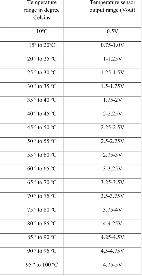
• Temperature sensor:
Temperature range in degree
Celsius
Temperature sensor output range (Vout)
10ºC 0.5V
15º to 20ºC 0.75-1.0V
20 º to 25 ºC 1-1.25V
25 º to 30 ºC 1.25-1.5V
30 º to 35 ºC 1.5-1.75V
35 º to 40 ºC 1.75-2V
40 º to 45 ºC 2-2.25V
45 º to 50 ºC 2.25-2.5V
50 º to 55 ºC 2.5-2.75V
55 º to 60 ºC 2.75-3V
60 º to 65 ºC 3-3.25V
65 º to 70 ºC 3.25-3.5V
70 º to 75 ºC 3.5-3.75V
75 º to 80 ºC 3.75-4V
80 º to 85 ºC 4-4.25V
85 º to 90 ºC 4.25-4.5V
90 º to 95 ºC 4.5-4.75V
95 º to 100 ºC 4.75-5V
Table 3. Temperature sensor readings
VIII.
ADVANTAGES
1. Sensors used have high sensitivity and are easy to handle.
2. Low cost system, providing maximum automation. 3. Closed loop design prevents any chances of disturbing the greenhouse environment.
4. User is indicated for changes in actuator state thereby giving an option for manual override.
5. Low maintenance and low power consumption.
6. The system is more compact compared to the existing ones, hence is easily portable.
7. Can be used for different plant species by making minor changes in the ambient environmental parameters. 8. Can be easily modified for improving the setup and adding new features.
9. Labor saving.
10. Provides a user-friendly interface hence will have a greater acceptance by the Technologically unskilled workers.
11. In response to the sensors, the system will adjust the heating, fans, lighting, irrigation immediately, hence protect greenhouse from damage.
12. Malfunctioning of single sensor will not affect the whole system.
13. Natural resource like water saved to a great extent.
IX.
CONCLUSION
Modbus based Multinode Irrigation automation is developed. By using this device the farmer can overcome from the problems associated when he wants to grow different type of plants at different plantation units which require different environmental conditions. He can control all the conditions from the master device itself so that his work is reduced. It is effective and cheap irrigation system. The productivity increases with less investments.
A step-by-step approach in designing the microcontroller based system for measurement and control of the four essential parameters for plant growth, i.e. temperature, humidity, soil moisture, and light intensity, has been followed. The results obtained from the measurement have shown that the system performance is quite reliable and accurate.
The system has successfully overcome quite a few shortcomings of the existing systems by reducing the power consumption, maintenance and complexity, at the same time providing a flexible and precise form of maintaining the environment. The continuously decreasing costs of hardware and software, the wider acceptance of electronic systems in agriculture, and an emerging agricultural control system industry in several areas of agricultural production, will result in reliable control systems that will address several aspects of quality and quantity of production.
REFERENCES
[1] “PC-Based Automation of a Multi-Mode Control for an Irrigation System”, Azzouz Benzekri, Kamal Meghriche, Larbi Refoufi, 1-4244-0840-7/07 ©2007 IEEE.
2011 International Conference on Communication Systems and Network Technologies.
[3] “An Automatic Control System of Precision Irrigation for City Greenbelt”, Yandong Zhao and Chenxiang Bai Beijing Forestry University Qing Hua donglu No.35.Beijing, China, 2007 IEEE Conference on Industrial Electronics and Applications.
[4] “Devices for Automatic Irrigation Based on GSM Network and Radio Communication”, Genghuang Yang, Boying Wen , Guohua Gao , ©2006 IEEE. [5] “Wireless Sensor Network based Remote Irrigation
Control System and Automation using DTMF code”, Vandana Dubey, Nilesh Dubey, Shailesh singh Chouhan, 2011 International Conference on Communication Systems and Network Technologies. [6] “Monitoring, Parameterization and Supervision of
Industrial Equipments with Handheld Computers over Modbus”, Antonio Heronaldo de Sousa, Valmor Adami Jr and Alcindo do Prado Junior, IEEE ISIE 2006, Montreal, Quebec, Canada.
[7] “Real-Time Automization Of Agricultural
Environment for Social Modernization of Indian Agricultural System”, Mahesh M. Galgalikar, 978-1-4244-5586-7/10/$26.00 C 2010 IEEE.
[8] “A wireless design of low-cost irrigation system using ZigBee technology”, Yiming Zhou, Xianglong Yang, Liren Wang, Yibin Ying, 2009 International Conference on Networks Security, Wireless Communications and Trusted Computing.
[9] “Automatic Irrigation System Based on Wireless Network”, Genghuang Yang, Yuliang Liu, Li Zhao, Shigang Cui, Qingguo Meng and Hongda Chen, 2010 8th IEEE International Conference on Control and Automation Xiamen, China, 2010.
Authors Biography
SHASHI RAJ K received Bachelor of Engineering degree in Electronics and Communication Engineering from the Vivekananda Institute of Technology, Bangalore and pursuing Master of Technology degree from Reva Institute of Technology and Management, Bangalore, affiliated to Visvesvaraya Technological University, in the field of VLSI Design and Embedded Systems. His research interests are VLSI based Agent applications, Wireless Communication and Computer Networking. He has published one national conference paper and one international journal. He is a member IEEE (MIEEE, India).
NAYANA D Kreceived B.E degree in Electronics and Communication from PES College of Engineering, Mandya and M.Tech degree from National Institute of Technology, Surathkal. She is currently working as an Associate Professor in Electronics and Communication Department of Reva Institute of Technology and Management, Bangalore. She is having a teaching experience of 18 years and her areas of interest are Wireless Communication and Computer Networking. She has published few papers in national and international conferences and journals.
Dr. Sunil S Manvi received M.E degree in Electronics from University of Visweshwariah College of