© 2018 IJSRSET | Volume 4 | Issue 1 | Print ISSN: 2395-1990 | Online ISSN : 2394-4099 Themed Section : Engineering and Technology
Analysis and Insight Based on Detailed Modeling
L Chakradhar1, P Muni Pratap2, D Mohan Reddy3
1PG Scholar, Dept of EEE, Amalapuram Institute of Management Sciences & College of Engineering,
Mummidivaram, East Godavari District, Andhra Pradesh, India
2Assoc. professor Dept of EEE, Amalapuram Institute of Management Sciences & College of Engg,
Mummidivaram, East Godavari District, Andhra Pradesh, India
3Professor & Principal, Amalapuram Institute of Management Sciences and College of Engineering,
Mummidivaram, East Godavari District, Andhra Pradesh, India
ABSTRACT
This paper presents modelling and examination of system oscillations in a wind farm. The way to deal with demonstrating utilizes point by point representation of a wind turbine generator and accumulation system including STATCOM power converter system control, encouraging a far reaching examination of the wind farm system. Different modes are grouped by recurrence of wavering. The point by point modular examination is utilized to describe the basic modes. Time-domain simulation also confirms the presence of these modes. The impact of wind farm working conditions and STATCOM control tuning on basic oscillatory modes are likewise surveyed and talked about in point of interest.
Keywords: Doubly fed induction generator (DFIG), eigenvalue, oscillations, stability, wind farm, wind turbine generator (WTG).
I.
INTRODUCTION
Conventional energy sources like thermal, fossil fuels like petroleum, coal, etc are depleting day by day thereby exploiting these resources to the fullest possible extent. Therefore, this calls for much attention and focus on the harnessing and
exploitation of the non-conventional energy
resources such as energy from sun, wind, rain, oceans, geothermal, ocean thermal, tides. This move will substantially contribute to the overall decrease in the much alarming greenhouse gas (GHG) emissions which might be a potential threat to the survival of human beings in the near future. This paper focuses on the Wind energy systems which are easy to harness and available everywhere in this world. Wind energy is already in use to maximum possible extent in many developing countries such as Denmark, Italy, etc. India is focusing on wind energy systems
seriously and try to implement a well-defined action plan in this context. Wind energy system are well suited for Indian agricultural scenario and can be used to supply power to agricultural pumping systems.
study will distinguish extra control prerequisites and determine the control outline for the wind farm operation. The impact of total on the modes will be examined in point of interest in a future distribution.
A viable wind farm group containing two separate wind farms is utilized for the demonstrating and investigation. Doubly sustained impelling generator (DFIG)- based WTGs have been utilized all through the wind farms and the system associates with the inland network utilizing a HVDC join. The VSC at the wind farm side gives wind farm voltage and recurrence control.
II.
MODELLING AND DESIGN OF DFIG
The doubly bolstered incitement generator is the better solution for variable speed machines with resistance ±30% of synchronous velocity. The grid and the rotor are specifically associated for the
primary stator winding is controlled with converters by means of slip rings as sown in figure 2.
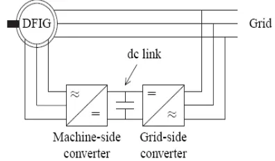
Figure 1. DFIG system with a Back to Back Converter
Figure 2. Equivalent circuit of DFIG
From application of Kirchhoff’s voltage law applied to the above circuit 2, the voltage expressions for stator and rotor windings are expressed as,
Vs = jω1Lm (Is + Ir + IRm) + jω1LsλIs + RsIs (1)
Vr/s= jω1Lm(Is + Ir + IRm) + jω1LrλIr + Rr/s*Ir (2)
0 = jω1Lm (Is + Ir + IRm) + RmIRm (3)
Rotor flux, stator flux, air-gap fluxes used in equations (1), (2) and (3) are defined below
Ψm = Lm (Is + Ir + IRm) (4)
Ψs= LsλIs +Ψm = LsλIs + Lm (Is + Ir + IRm) (5)
Ψr= LrλIr +Ψm = LrλIr + Lm (Is + Ir + IRm) (6)
The electro-mechanical torque is obtained from the above equations is expressed as Te = 3npImΨrIr*= 3npImΨmI∗r (7)
The rotor and stator powers are determined as Ps = Re [Ss] = 3Rs |Is|2 + 3Rm |IRm|2 +3ω1Im [ΨmI∗r]
≈ 3ωIm [ΨmI∗r] (8)
Pr= Re [Sr] = 3Rr|Ir|2−3ω1sIm [ΨmI∗r]
≈ −3ω1sIm [ΨmI∗r] (9)
From these DFIG mechanical power equations are calculated by
Pmech = 3ωrIm [ΨmI∗r] =3ω1Im [ΨmI*r] − 3ω1sIm[ΨmI∗r ] (10)
Figure 3. DFIG Connected to Wind Turbine
Closed Loop Control Diagram for Rotor Side Controller
By considering the simplified equivalent circuit for stator winding as shown in figure 2 and write the equations by using KVL as
dt
d
R
I
V
rr r r
(11)
r
L
rI
r
M
I
se
j(12)
Substituting the value of
ψ
rin above equation e getr
V = r
s j s s r r r
r
L
I
M
e
L
M
I
L
dt
d
R
I
2
(
=
j
s s r
s r r r
r e
L M dt
d I L M I L dt
d R
I
2
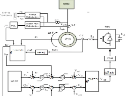
Figure 4 demonstrates the general RSC control plan which is having two course circles. The dynamic and receptive powers of the DFIG is controlled by the external circle and direct pivot current part Idr*, quadrature hub current segment Iqr* are created. Internal circle current regulation is the second fell control circle. Vdr0 and Vqr0 are the from the two directed current controllers yields. Furthermore, these signs are utilized for producing Pulses to RSC converter by PWM strategy.
Figure 4. Control Diagram for the rotor side controller
Closed Loop Control Diagram Grid Side Converter
Form the equivalent circuit shown in figure 2. Applying KVL to above circuit we get
dI
cg c f f c
c
dt
v
dI
L
R
I
v
(15)
Transform the above three phase coordinates in to two phase d-q transformation and separate real & imaginary terms we get
g sq f s sd f f sd
sd
w
L
I
v
dt
dI
L
R
I
v
sq sq f f sqw
sL
fI
sddt
dI
L
R
I
v
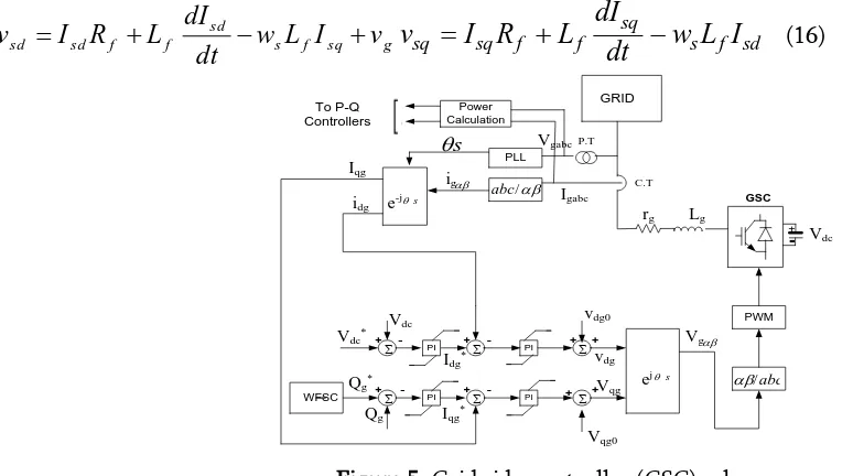
(16)GSC + - PI PI PI PI + + + + + + -- + + WFSC PWM Power Calculation PLL / abc abc / e-j ej s s Vdc
* Vdc
Qg*
Qg
Idg *
Iqg*
vdg0
vdg
Vqg
Vqg0
Vg GRID P.T C.T Vgabc Igabc To P-Q Controllers Vdc
rg Lg
idg Iqg ig s
Figure 5. Grid side controller (GSC) scheme
Figure 5 demonstrates the complete shut circle control chart for the lattice side converter and it having two fell control circles. The responsive power is by implication controlled by the dc join voltage controlling done by the external control circle for creating the reference signs of the d-pivot current segment idg* and q-hub current part iqg* for the internal circle current regulation. At that point these signs are utilized for producing beats with the assistance of PWM procedure
max , max , max , max
, mi Li si ri
ei
P
P
P
P
P
The stator active power Ps can be written as
)]
(
)
(
[
2
3
)
(
2
3
2 2qs ds s qr ds dr qs m s qs qs ds ds
s
v
i
v
i
L
i
i
i
i
r
i
i
P
The rotor side active power can be expressed
[
(
)
(
)]
2
3
)
(
2
3
2 2qr dr r qr ds dr qs m s qr qr dr dr
r
v
i
v
i
s
L
i
i
i
i
r
i
i
P
III.
LAYOUT OF WIND FARM
A sensibly huge wind farm (500–800 MW) will contain numerous several WTGs spread over a territory covering numerous square kilometers. WTGs are associated with a medium voltage system
called the "authority system." Wind farm
transformers are utilized to venture up the voltage level before transmitting power to the network. For seaward wind farms where the transmission separation is 100 km or more, VSC HVDC is practical for lattice association.
The case wind farm system utilized as a part of the present work contains two wind farms of limit 465
MW (93 × 5 MW) and 165 MW (33 × 5 MW). They are named as wind farm 1 (WF1) and wind farm 2 (WF2), separately. Each WTG unit in the wind farm system is shaped of a wind turbine, a DFIG, and a cushion mounted transformer. A schematic graph of the 5-MW DFIG-based WTG utilized all through the wind farm system is appeared in Figure 1. The DFIG rotor is empowered through the rotor-side converter (RSC) and the matrix side converter (GSC) as appeared in the figure. The transformer ventures up the 0.6-kV voltage delivered by the DFIG to 33 kV.
the wind farm transformer to a state of normal coupling (PCC) with the VSC and a HVDC join interfaces the PCC with the fundamental air conditioning lattice. The link separation between the PCC and the wind farm transformer terminals (132 kV links) is thought to be 30 km. Both of the wind farms are separated into two zones, zone 1 and region 2. The voltage and recurrence at the PCC are managed utilizing the VSC.
Figure 6. Single line diagram showing high voltage-side of wind farm collector system.
Operating Conditions
In this paper, four experiments are considered for examination. In all the cases, the WTGs are thought to be working over the appraised wind speed and have a nonzero pitch edge. The experiments are as per the following.
Test-1: The base situation where all the WTGs of both the wind farms are in administration.
Test-2: WF2 is halfway closed down. Just five WTGs in WF2 are working, which are situated toward the end of the strings. They are chosen such that the whole 33-kV authority links remain invigorated. Test-3:WF1 A2 is in part close down. Just eleven WTGs in WF1 A2 are working which are situated toward the end of the strings. All WTGs in WF1 A1, and WF2 are creating evaluated yield.
Test-4: WF1 A1 and WF1 A2 are in part closed down. Just 10 WTGs in WF1 A1 and 11 WTGs in WF1 A2
STATCOM and its Control Technique
A STATCOM is a one of the repaid gadget which is acquired from the FACTS family [11] and is a mix of power electronic converter alongside reactor. For the most part, the converter is built by the utilization of completely controlled gadgets, for example, GTO, IGBT or MOSFET. The primary reason for this STATCOM converter control method is utilized to repay the deviations in power system for enhancing power quality. In this paper network interfaced wind turbine based STATCOM control plan is proposed for enhancing the unwavering quality of electrical power [12].
• The Dc voltage acquired for STATCOM is created from Solar Cells. The schematic outline of Static compensator is given in figure 7.
Vdc
Cdc
Controller
Firing angle DC voltage
Uref Voltage
source converter
3-phase AC voltage U
UT Phase
Load
Reactive current injection
PCC
Coupling X TransformerT Transmission Line U
T Generation
Power flow
Iq
Figure 7. Basic block diagram for static compensator
The usage of various sorts of electrical burdens in three stage system, creates an unbalances in current, which causes the temperamental power [13]. In this way to maintain the electrical dependability the statcom controller assumes a key part. In this statcom control strategy, the reference voltage and dc join capacitor voltages are analyzed and the outcome acquired from this is changed over to two stage organizers called as orthogonal vectors.
Artificial Neural Networks:
and the rules obtained based on the if-then statements is eliminated [7]. For simplicity, we considering the examined ANN has two inputs and one output. In this network, each neuron and each element of the input vector p are connected with weight matrix W. The hybrid learning algorithms are implemented for obtaining the values of system parameters. These learning algorithms is a function of linear and non-linear parameters. These explanations are implemented in Matlab/Simulink software.
Figure 8. ANN architecture for a two-input multi-layer network
Where the two crisp inputs are x and y, the linguistic variables associated with the node function are Ai and Bi. The system has a total of five layers are shown in Figure 8.
IV.
SIMULATION OF THE WIND FARM
A nonlinear element reenactment is done utilizing the working condition test-1, where all the WTGs are working at appraised working condition. They are set to control receptive power yield at their terminal and the VSC manages voltage at the PCC. Amid the recreation, one of the accompanying two unsettling influences is connected to the system at time t = 1 s: 1) a 10% expansion in the PCC reference voltage and (b) the responsive power reference data of all the WTGs set to zero.
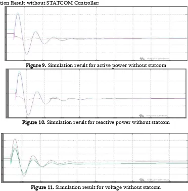
Case 1: Simulation Result without STATCOM Controller:
Figure 9. Simulation result for active power without statcom
Figure 10. Simulation result for reactive power without statcom
Case 2: Simulation Result with STATCOM Controller:
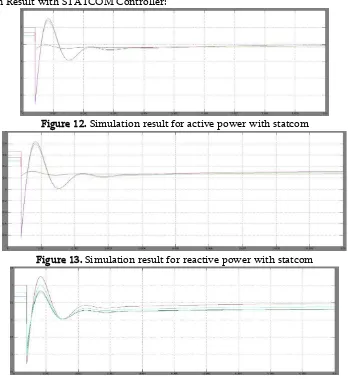
Figure 12. Simulation result for active power with statcom
Figure 13. Simulation result for reactive power with statcom
Figure 14. Simulation result for voltage with statcom
V.
CONCLUSION
This paper describes the modeling of a wind farm system associated with a STATCOM and clarifies different oscillatory modes present in the system. The oscillatory modes are grouped into various classifications in view of the recurrence and damping proportion. Three oscillatory modes in the gatherer system are distinguished which have low damping, and frequencies in the scope of 100–500 Hz. They are essential as a result of their closeness to sounds of the
power recurrence, especially on account of STATCOM symphonious era. The damping of the medium recurrence modes relies on upon the working state of wind farm. The outcome is critical as the wind farm working conditions will ceaselessly fluctuate contingent upon the predominant wind conditions. Additionally, it is found that the STATCOM controller parameters impact the damping of the medium-recurrence modes. The time-space results affirm the nearness of the modes.
VI.
REFERENCES
[1]. S. Alexander. (2012, Jan. 11). Wind Power
energie.de/en/infocenter/articles/wind-power-lossesgrid- disconnections-much-69-percent
[3]. G. Tapia, A. Tapia, and J. X. Ostolaza, "Two alternative modeling approaches for the evaluation of wind farm active and reactive power performances," IEEE Trans. Energy Convers., vol. 21, no. 4, pp. 909-920, Dec. 2006.
[4]. V. Akhmatov and H. Knudsen, "An aggregate
model of a grid connected, large-scale, offshore wind farm for power stability investigations: Importance of windmill mechanical system," Int. J. Elect. Power Energy Syst., vol. 24, no. 9, pp. 709-717, Nov. 2002.
[5]. K. Ben Kilani and M. Elleuch, "Simplified
modelling of wind farms for voltage dip transients," in Proc. 9th Int. Multi-Conf. Syst. Signals Devices (SSD), Mar. 2012, pp. 1-6.
[6]. K. Rudion, Z. Styczynski, A. Orths, and O.
Ruhle, "MaWind-Tool for the aggregation of wind farm models," in Proc. Power Energy Soc. Gen. Meeting Convers. Del. Elect. Energy 21st Century, Jul. 20-24, 2008, pp. 1-8.
[7]. A. Perdana and C. Ola, "Aggregated models of a
large wind farm consisting of variable speed wind turbines for power system stability studies," in Proc. 8th Int. Workshop Large-Scale Integr. Wind Power Power Syst. Transmiss. Netw. Offshore Wind Farms, 2009, pp. 568-573. [8]. F. Mei, "Small-signal modelling and analysis of doubly-fed induction generators in wind power applications," Ph.D. dissertation, Department of Electrical and Electronic Engineering, Imperial College London, London, U.K., 2008.
[9]. G. Quinonez-Varela, G. Ault, O. Anaya-Lara,
and J. McDonald, "Electrical collector system options for large offshore wind farms," IET Renew. Power Gener., vol. 1, no. 2, pp. 107-114, Jun. 2007.
[10]. W. Lin, J. Wen, J. Liang, S. Cheng, M. Yao, and
N. Li, "A three-terminal HVDC system to bundle wind farms with conventional power plants," IEEE Trans. Power Syst., vol. 28, no. 3, pp. 2292-2300, Aug. 2013.
[11]. S. Dutta and T. Overbye, "A clustering based wind farm collector system cable layout
design," in Proc. IEEE Power Energy Conf. (PECI’11), Feb. 2011, pp. 1-6.
[12]. S. Kuenzel, L. P. Kunjumuhammed, B. C. Pal,
and I. Erlich, "Impact of wakes on wind farm inertial response," IEEE Trans. Sustain. Energy, vol. 5, no. 1, pp. 237-245, Jan. 2014
[13]. A. Marinopoulos et al., "Investigating the
impact of wake effect on wind farm aggregation," in Proc. IEEE Power Tech, Trondheim, Norway, Jun. 19-23, 2011, pp. 1-5.
[14]. S. Hao, Y. Zhang, X. Li, and Y. Yuan,
"Equivalent wind speed model in wind farm dynamic analysis," in Proc. 4th Int. Conf. Electr. Utility Deregul. Restruct. Power Technol. (DRPT), Jul. 6-9, 2011, pp. 1751-1755.
[15]. J. K. Sethi, D. Deb, andM.Malakar, "Modeling of
a wind turbine farm in presence of wake interactions," in Proc. Int. Conf. Energy Autom. Signal (ICEAS), Dec. 28-30, 2011, pp. 1-6. [16]. E. Muljadi et al., "Equivalencing the collector