* To whom all correspondence should be addressed. E-mail: [email protected]
Development of a System for Automated Finding
and Tracking of Thermal Objects
Yuri Anatolievich Krupnov, Yegor Maksimovich Kovrigo, Dmitry Borisovich Rygalin and Olga Valeryevna Sedova
National Research University of Electronic Technology (MIET), 124498, Moscow, Zelenograd, Shokina Square, Building 1
DOI: http://dx.doi.org/10.13005/bbra/1980
(Received: 20 February 2015; accepted: 18 April 2015)
The presented paper describes the results of an applied research, the aim of which was to develop an optimum configuration of an optical system capable to detect and track thermal objects situated at 0.5 … 10 m from a point of sight. In the course of the development of the design of the system we reviewed components from various producers, carried out selective comparisons of them and chose the most suitable for the achievement of the goal of the research. During the study we developed an optical scheme of infrared module and an objective consisting of germanium-made lenses. On the basis of the optical scheme we developed the design of the optical module with the combined optical system with an infrared detector of optical channel combined with an image detector in visible spectrum, as well as selected the material of the body taking into account the decrease of the weight of the system. In the course of the study it was decided to include an automatic focusing mechanism for the infrared objective and to measure focal length using a range finder. The study discusses advantages and disadvantages of the most widely spread types of range finders; the most suitable range finder was selected according to the set goal of the research. In addition, the paper discusses a problem of selection of a vacuum pump for the decrease of molecular heat exchange. The breadboard construction obtained in the result of the study represents a finished module and allows to install it on any base.
Key words: optical system, monitoring system, infrared module, tracking of thermal objects, finding of thermal objects, focusing.
Nowadays systems of remote monitoring are in demand in many fields. Security of private establishments or even countries pertains to those fields. As about systems for objects’ security, first of all, the most widely spread are video surveillance systems. That kind of systems allows to monitor a certain object remotely. However, video surveillance systems widely spread nowadays have one significant disadvantage: their cameras operate in visible part of spectrum. However,
security often requires finding of thermal radiation by means of infrared optical systems.
In world practice, vision systems are provided with infrared channel (IR-channel) and television channel, which allows to increase sharpness of image (for instance, in systems with advanced visualization).
In order to obtain a sharper image, the major part of the existing systems uses manual or automatic focusing. Automatic focusing mechanism usually consists of a sensor, a control system and a drive, which moves an objective’s mount or some of its individual lenses.
During design of the system for automatic finding and tracking of thermal objects (SAFTTO), initially it was decided to select a sensor for the infrared optical module, design the optical system, select material for the module’s body, and then to select additional components for SAFTTO.
Selection of IR sensor
The infrared optical module consists of the infrared sensor and the objective. In order to decrease the weight of SAFFTO, we decided to use uncooled infrared sensors (a microbolometric matrix can be used for that purpose).
The number of IR-matrix elements defines the quality of the obtained infrared image. Aside from functional applicability, minimal size of a thermographic camera’s matrix, which can be used for various purposes, can be specified in normative documents. For example, according to GOST R 54852-2011, the size of a matrix must be not less than 160 x 120, and according to RD-13-04-2006 – not less than 240 x 128 1. Size of the sensor’s matrix defines resolution of IR objective. Nowadays, the most widely spread types are optical systems with sizes of 160 õ 120, 320 õ 240 and 640 õ 480 pixels. Thermographic cameras are example of that kind of systems.
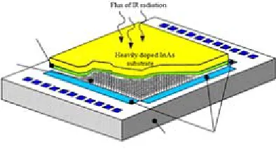
Design of a matrix detector, which is a part of a thermographic camera is presented in Figure1 1.
a) Raytheon (USA); b) Flir (USA); c) NEC (Japan); d) Ulis (France); e) Sensonor (Norway);
f) Astrohn Experimental Design Bureau (Russia).
In order to meet requirements of a performance specification we selected the following modules and matrices:
a) Astrohn Iridium 384 (Figure 2)2; b) Flir Tau324 (Figure 3)3.
Fig. 1. Design of the matrix detector
The main producers of IR bolometric matrices and modules on their basis available in Russia are as follows:
Fig. 2. Module Iridium 384
Fig. 3. Module TAU 324
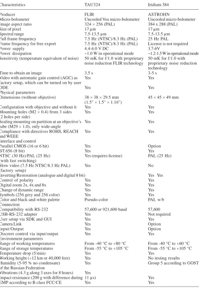
Comparison of Flir TAU320 and Astrohn Iridium 384 modules are presented in Table 1 below. Module Iridium 384 is the best solution for achieving goals of the research as it has the highest resolution with other characteristics being similar (Table 1).
Design of the objective
After selection of the sensor we designed the objective, which allowed to observe objects situated at 0.5 … 10 m from viewpoint.
Table 1. Comparison of IR modules
Characteristics TAU324 Iridium 384
Producer FLIR ASTROHN
Micro-bolometer Uncooled Vox micro-bolometer Uncooled micro-bolometer
Image aspect ratio 324 × 256 (PAL) 384 x 288 (PAL)
Size of pixel 17 µm 17 µm
Spectral range 7.5-13.5 µm 7.5-13.5 µm
Full frame frequency 7.5 Hz (NTSC)/8.3 Hz (PAL) 25 Hz PAL
Frame frequency for free export 7.5 Hz (NTSC)/8.3 Hz (PAL) License is not required
Power supply 4.4-6.0 V DC 3.7-6V
Power dissipation ~1.0 W in operational mode ~1.2-1.5 W in operational mode Sensitivity (temperature equivalent of noise) 50 mK for f/1.0 with proprietary 50 mK for f/1.0 with
noise reduction FLIR technology proprietary noise reduction technology
Time to obtain an image 3.5 s 3-5 s
Video with automatic gain control (AGC) as Yes Yes
factory setup, which can be turned on by user
DDE Yes Yes
Physical parameters
Dimensions (without objective) 38 × 38 × 29.5 mm 45 × 45 × 49 mm (1.5" × 1.5" × 1.16")
Configuration with objective and without it Yes Yes
Mounting holes (M2 × 0.4) from 3 sides Yes Yes
(2 holes per side)
Sealing mounting on partition at an objective’s Yes Yes tube (M29 × 1.0), only wide-angle
Compliance with directives ROHS, REACH Yes Yes
and WEEE
Interface and control
Parallel CMOS (16 or 6 bit) Yes Option
BT.656 (8 bit) Yes Yes
NTSC (30 Hz)/PAL (25 Hz) Yes (requires license) PAL (25 Hz) (with fast switching)
Slow video (7.5 Hz NTSC/8.3 Hz PAL) Yes No
(factory setup)
Inverting/Restoration (analogue and digital 8 bit) Yes Yes
Control of polarity Yes Yes
Digital zoom 2x, 4x and 8x Yes Yes
Change of dynamic range Yes Yes
Symbols (256 grey and 256 color) Yes Yes
Color and black-and-white palette Pseudo-color PAL w/b
Connection
Compatibility with RS-232 57,600 or 921,600 baud 57,600
USB-RS-232 adapter Yes Not required
User setup via SDK and GUI Yes Yes
Camera Link Yes Option
Input/Output Yes Option
Discreet control via input/output Yes Yes
Environment parameters
Range of working temperatures From -40 °C to +80 °C From -40 °C to +60 °C Range of storage temperatures From -55 °C to +105 °C From -55 °C to +105 °C
Temperature drop (5/min) Yes Yes
Working height (+12 km or 40,000 feet) Yes No testing results
Humidity (5-95 % no condensate) Yes Group 5 according to GOST
of the Russian Federation
Vibrations (4.3 g along 3 axes for 8 hours) Yes
Impact resistance (200 g with difference during 11 µs) Yes
with 384 × 288 form factor, size of sensitive area of 10.88 × 8.16 mm and size of sensitive layer of an element of 17 ×17 µm.
It is worth mentioning that size of image of a point source must not exceed size of a sensitive element.
Focal length of the objective was selected according to the necessary value of field of vision 2W = 30°, which corresponds to the large size of the microbolometric matrix:
max
'
'
tgW
L
f
∗
=
tgW
L
f
'
=
'
max
...(1)
where
f 2 – focal length of the objective, 2W – field of vision,
L2 – size of a sensitive area.
Field of vision of the objective is 30° × 22.7° (37° – diagonal). The objective layout is presented in Figure 4, where 1 – first lens with a positive meniscus, convexity directed towards the objective, 2 – second lens with a negative meniscus, concavity is directed towards the objective, 3 – third length with a positive meniscus, concavity is directed towards the object, 4 – fourth lens with a positive meniscus, convexity aimed towards the object. Backward focal distance S2 f2 = 9.8 mm.
Lenses of the objective have antireflective coating for the working range.
Weight of the objective is 0.0308 kg. Length of the objective with the backward focal distance is 42.3 mm.
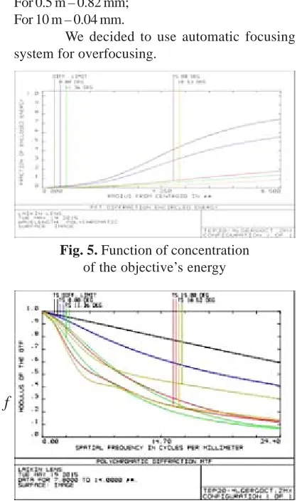
distances of 0.5 … 10 m it is necessary to carry out overfocusing:
For 0.5 m – 0.82 mm; For 10 m – 0.04 mm.
We decided to use automatic focusing system for overfocusing.
Fig.4. Layout of the objective
Figure 5 demonstrates function of concentration of the objective’s energy.
Figure 6 demonstrates contrast transfer function of the objective.
The objective features high image quality, which allows to effectively use it with bolometric matrices including matrices with 17 µm pixel.
In a case of using of that objective at
Fig. 5. Function of concentration of the objective’s energy
Fig. 6. Contrast transfer function of the objective
Selection of the body’s material
For manufacturing of the body we selected several types of materials (stainless steel 4, D16T aluminum, PA6 polyamide (kaprolon)).
Initially, we selected AISI 304 steel as the main structural material. That grade of steel is the most widely spread and universal austenitic chrome-nickel heavily-doped corrosion-resistant steel, together with AISI 304L. That grade of steel has the following advantages as structural material: a) Resistance to oxidation;
b) Good weldability;
c) Mechanical processibility;
AISI 304 (08H18N10) steel has the following characteristics 4:
a) Density 7,800 kg/m3; b) Brinell hardness 123; c) Knoop hardness 138;
d) Tensile strength, Ultimate 505 MPa; e) Tensile strength, Yield 215 MPa; f) Elongation at Break 70 %;
g) Modulus of Elasticity 193-200 GPa; h) Poisson’s ratio 0.29;
i) Shear Modulus 86-200 GPa; j) Electrical Resistivity 7.2e-5Ω/cm; k) Magnetic Permeability 1.008; l) Specific heat capacity 0.5 J/(g.K); m) Thermal conductivity 16.2 W/(m.K); n) melting temperature 1,400-1,455 °C.
Designed weight of the module manufactured from AISI 304 steel was, approximately, 300 g. It was decided to select material, which would allow to decrease weight of the IR module.
Weight of the module with the same design can be decreased by means of application of other materials. We used PA6 kaprolon (polyamide) as structural material.
Kaprolon has the following characteristics 5: a) Density 1,150-1,160 kg/m3;
b) Melting temperature 220-225 °C. c) Working temperature 110 °C; d) Modulus of elongation 3,000 MPa; e) Rupture at tension stress of 80 MPa; f) Relative elongation 15-30 %;
g) Water absorption for 24 hours 1.5-2 %; h) Thermal conductivity 16.2 W/(m.K); i) Dielectric permeability 3.3;
j) Brinell hardness 160-180 MPa; k) Breakdown strength 30-35 kV/mm; l) Charpy impact energy 20-70 kJ/m.
Design weight of the IR module decreased to 60 g. However, the difficulty in manufacturing kaprolon body is that range of kaprolon products (plates, bars, blocks) doesn’t include pipes. Therefore, manufacturing of the bodies will require turning and milling, which will lead to high amount of waste materials. In addition, mechanical processing of kaprolon can lead to formation of residual stresses in the material, which, in turn, can lead to failure of calibration of the device. Another method of manufacturing using polyamides is jet molding. Jet molding doesn’t
produce waste materials, but it requires large investments for preparation for manufacturing.
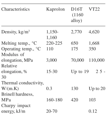
After design of the optical module we simulated thermal processes in Ansys software, which demonstrated that kaprolon body doesn’t provide enough heat removal from IR matrix. Thus, there is a need to select material with density close to kaprolon, but with higher thermal conductivity. Among structural materials with high thermal conductivity there are copper (401 W/m’”Ê) and silver (430 W/m’”Ê). However, these materials have not only high thermal conductivity, but also high density 8,940 kg/m3 and 11,500 kg/m3, respectively. High density makes application copper and silver alloys unreasonable. Light materials with high thermal conductivity and density, which is close to those of kaprolon are alloys of aluminum and titanium. We selected aluminum alloy D16T and titanium alloy VT22 (Table 2) as applicable materials.
Table 2. Comparative characteristics of structural materials
Characteristics Kaprolon D16T VT22 (1160 alloy)
Density, kg/m3 1,150- 2,770 4,620
1,160
Melting temp., °C 220-225 650 1,668 Operating temp., °C 110 175 350 Modulus of
elongation, MPa 3,000 70,000 110,000 Relative
elongation, % 15-30 Up to 19 2 5 -30
Thermal conductivity,
W/(m.K) 0.3 130 Up to 20
Brinell hardness,
MPa 160-180 420 103
Charpy impact
energy, kJ/m 20-70 0.12
From the table it is clear that D16T alloy is the most suitable for solution of the problem. Thus, design weight of IR-module is, approximately, 120 g, and heat removal through walls of the body is sufficient for cooling of IR-matrix, which allows not to avoid forced cooling.
According to the optical scheme it is necessary to move the objective in ranger 0.04-0.082 mm. For that a notch is to be made on the body similar to regular photo cameras of visible spectrum. Focusing in range of distance 0.5 … 10 m will be carried out by means of rotation of the objective.
Image registration in visible range
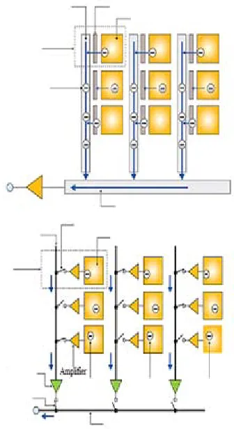
We considered CMOS and CCD matrices as options for image registration in visible range (Figure 8) 6.
CCD stands for charge-coupled device. The principle of operation consists of initial selection of image in analogue mode and further digitalization 7.
CMOS stands for complementary metal-oxide-semiconductor
The main advantages of CMOS matrices as compared to CCD are as follows 6:
a) Low manufacturing cost.
b) 100 times lesser power consumption. c) High performance.
d) Capability to free reading of cells, which eliminates smearing effect.
CMOS has the following disadvantages as compared to CCD
a) Smaller light sensitivity due to small size of a light-sensitive cell as compared to pixel’s size, the major part of space is occupied by electronic components.
b) Increase of noise on an image due to need to use of preamplifier.
c) Rolling shutter effect. It is observed, generally, in cases of taking images of rapidly moving objects, and it consists in distorted imaging of objects.
Advantages of CCD as compared to CMOS:
a) Electronic shutter, which allows sharp fixing of rapidly moving objects.
b) Absence of vibrations and rolling shutter effect.
For solution of the set problems the most important factors were power consumption and low cost. Appearance of rolling shutter effect was considered unlikely, because speed of scanning of space was comparatively low. Thus, the optimal solution was application of CMOS-matrix for registration of images in visible part of spectrum.
Nowadays, there are following main producers of CMOS-matrices
a) CMOSIS (Belgium); b) Aptina (USA); c) Sony (Japan); d) Anafocus (Spain).
For applications related with image recognition at 0.5-10 m required and sufficient solution is a module with 720p resolution. As the result, we selected ICX278AK matrix of 1/4" form-factor 8.
Fig. 7. Overview of IR-module
Selection of range finder
In a case of combination of two objectives the main goal will be to focus both of them at one point in range 0.5-10 m.
For focusing of IR-objective we planned to develop the objective with germanium-made lenses and electronic focusing. An objective with electronic control also will be installed onto the matrix of visible range. Thus, during manufacturing it will be necessary to only adjust both objectives for operations in the designated range of distances, In order to automatically focus objectives it is necessary to know distance to observed object. In order to measure distance to an object it is necessary to use a range finder.
Nowadays the most widely spread type of range finders for domestic applications are laser range finders (Figure 9) and ultrasonic range finders (Figure 10) 10. The discussed problem requires distance measurement in range of 0.5-10 m.
ultrasonic range finders. Laser range finder allows to detect precise distance for any point of any size. Maximum distance of measurement is 250 m, however, it, generally, doesn’t exceed 50 m; moreover, laser signal is not dampened by carpets and door curtains. At that, measurement inaccuracy is minor – about 1-5 mm. However, in outdoors conditions with bright sunlight laser beam losses its brightness, which complicates operation at big distances.
Ultrasonic range finders are operating in a manner, which is similar to sonic depth finder: the device sends directed beam of sound waves in ultrasonic range (about 40 KHz), picks up their reflection from a distant object; after that on a basis of analysis of time of sound waves’ return it calculates the distance and shows values on a display. That kind of design has disadvantages, the main of which is that the end point must be a quite big object, which can reflect cone-shaped beam of sound waves. As the beam is cone-shaped maximum measurement distance doesn’t exceed 35 m. Also, it worth mentioning that many materials (fabrics, carpets, sound insulation, etc.) can effectively dampen sound and therefore measurement results will have higher inaccuracy. Analysis showed that for solution of the set task a laser range finder is better as compared to an ultrasonic range finder. It is related with the fact that there can be several observed objects, and size of an object can be small.
A range finder must meet the following requirements:
a) Minimum measurement distance 0.5 m; b) Maximum measurement distance not less
than 10 m;
c) Measurement inaccuracy 5 cm; d) Analogue and digital output.
We selected a laser range finder from the following producers: Astech (Germany), Flir (USA) and Schmitt Measuring Systems (USA).
There are many laser range finders that meet the requirements among the products of the mentioned producers.
Astech company: range finders of LDM30x, LDM40x, LDM51 and LDS30 series 11,12. Flir company: laser ranger finders of K series and very compact laser range finders of MLR series.
Schmitt Measuring Systems company:
Se i
Re Ti
Micro compu ter Data represe ntation
Data transfer
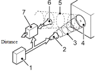
Fig. 8. Scheme of operation of a laser range finder
1 – generator, 2 – ultrasonic transmitter, 3 – transferred ultrasonic pulses, 4 – measure object, 5 – reflected wave (echo), 6 – ultrasonic receiver, 7 – calculator unit
Fig. 9. Scheme of operation of an ultrasonic range finder
laser range finders AR200, AR1000 and AR4000 13. Laser range finders of these producers have established reputation in world markets. For solution of the discussed design problem we excluded range finders supplied in a body as a finished product from the selection. The main reason for that was large sizes of a body and big weight of a device.
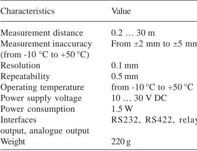
Fig. 10. Module RF41
Table 3. Specification of module RF41
Characteristics Value
Measurement distance 0.2 … 30 m
Measurement inaccuracy From ±2 mm to ±5 mm (from -10 °C to +50°C)
Resolution 0.1 mm
Repeatability 0.5 mm
Operating temperature from -10°C to +50°C Power supply voltage 10 … 30 V DC Power consumption 1.5 W
Interfaces RS232, RS422, relay
output, analogue output
Weight 220 g
Fig. 11. LDS30M
Fig. 12. Module RF51
Thus, we reduced the selection set to the following modules:
a) OEM laser module RF41 (Astech) (Figure 10, Table 3) 14;
b) OEM laser module LDS30M (Astech) (Figure 11, Table 4) 12;
c) OEM laser module RF51 (Astech) (Figure 12, Table 5) 15;
d) MLR 100 (Flir) (Figure 13, Table 6) 16.
Fig. 13. MLR 100
Table 4. Specification of module LDS30M
Characteristics Value
Measurement distance 0.2 … 30 m Measurement inaccuracy ±5 mm
Resolution 0.1 mm
Repeatability ±2 mm
Operating temperature from 0°C to +50°C Power supply voltage 6.5 … 7 V DC
Power consumption 3 W
Interfaces RS422
Among these modules the most suitable for installation are RF41 14 and RF51 15. Another important advantage of these modules is power supply voltage of 10 … 30 V, because that voltage is required for step motors used in the design. The main disadvantage of RF41 module is its high weight. As a laser range finder is to be installed on a rotating platform, it is reasonable to reduce weight of a laser range finder as much as possible. Modules LDS30M12 and MLR 10016 have the lowest weight. They have the common disadvantage, which is power supply voltage of 6.5 … 7 V, which will require installation of an additional power supply; however, a power supply is installed inside the electronic module, but not on the rotating platform, therefore its weight is not critical. As the result, we selected LDS30M12 module for solution of the discussed design problem, because it is the most convenient from the point of view of installation into the body.
Design of the body’s model
The IR-module together with the module of image registration in visible range and a laser range finder is installed in the plastic case.
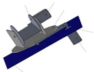
In order to meet the requirement for scanning of space the module of image registration of the micro system device (MSD) is installed on the rotating platform, which allows to rotate the optical part for at least 90 degrees in horizontal plane and at least 30 degrees in vertical plane.
The rotating platform consists of a horizontal base plate for rotation in horizontal plane. Rotation of the plate is carried out by means of the step motor with a belt drive. A carriage for vertical rotation, on which the optical module can be installed, is attached to the platform. The carriage for vertical rotation is attached using bearings. Rotation of the carriage is carried out by means of the step motor and the belt drive (Figure 15).
Table 5. Specification of module RF51
Characteristics Value
Measurement distance 0.1 … 500 m Measurement inaccuracy ±1 mm
Resolution 0.1 mm
Operating temperature from -40°C to +60°C Power supply voltage 10 … 30 V DC
Power consumption 10 W
Interfaces RS422
Weight 50 g
Table 6.Specification of module MLR100
Characteristics Value
Measurement distance 0 … 30 m Measurement inaccuracy ±5 mm
Resolution 0.1 mm
Repeatability ±2 mm
Operating temperature from 0 °C to +50 °C Power supply voltage 6.5 … 7 V DC
Power consumption 400 mW
Interfaces 3-wire serial clock,
RS232
Weight 22 g
Fig. 14. Module of image registration
Fig. 15. Rotation mechanism of SAFTTO
As the step motor we tentatively selected FL28STH51-0956A motor produces by SPC Electroprivod 17 with the following characteristics: a) Capacity – 11.5 W in quasi-static mode. b) Power supply voltage – 12 V in quasi-static
mode.
c) Torque – 0.9 kg.cm2.
Thus, the total consumed power of the rotation mechanism is 23 W with the total current consumption of 1.8 A, while according to the requirements specification the current consumption is not to exceed.
The total weight of the rotation mechanism is approximately 550 g.
The plates and the carriage are produced from ABS-plastic in order to reduce weight of structure.
The rotation mechanism with the installed module of image registration is mounted onto SAFTTO control unit (Figure 16).
There are several modules placed inside the control unit:
a) Power supply module. b) Step motors control module. c) Vacuum pump control module. d) Focusing module.
The power supply module distributes power coming to MSD between the components.
The vacuum pump control module is a power module, which receives data from a vacuum sensor, which is situated in the IR-module, and controls a vacuum pump.
As the vacuum sensor we selected PSE56119 with measurement range of 0~-101 kPA.
Selection of the vacuum pump
Analogue signal of the sensor comes on controllers of a control card of the vacuum pump. In a case a value from the sensor is lower than a setting, the vacuum pump is started. We selected the vacuum pump for the solution of the discussed design problem from plate-rotor, membrane and spiral type vacuum pumps.
Plate-rotor vacuum pumps can belong to two sub types: oil and non-oil. That type of the vacuum pump is the most efficient in range of low vacuum. The main advantages of that kind of pumps: air cooling, capability to pump out vapors, low level of vacuum with large capacity.
Membrane vacuum pumps are the most compact, practical and multi-functional type of vacuum pumps. The main advantages of that kind
Fig. 16. Rotating platform with image registration module
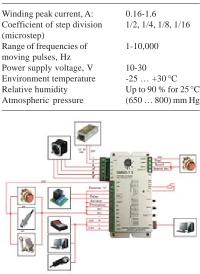
Step motors control module is a power module, which supplies power from the power supply module to step motors. The module controls speed of rotation of step motors to provide an object’s tracking and direction of the motors’ rotation. We decided to use two programmable step control units produced by SPC Electroprivod SMSD-1.5 as the module for control of the rotating platform with two step motors (Figure 17, Table 7)18. That unit was selected as the recommended by SPC Electroprivod for control of FL28STH51-0956A step motors.
Table 7. Specification of SMSD-1.5 control block
Winding peak current, A: 0.16-1.6
Coefficient of step division 1/2, 1/4, 1/8, 1/16 (microstep)
Range of frequencies of 1-10,000 moving pulses, Hz
Power supply voltage, V 10-30 Environment temperature -25 … +30°C Relative humidity Up to 90 % for 25°C Atmospheric pressure (650 … 800) mm Hg
of pumps is their simple design, small sizes and ease of operation.
Spiral-vacuum pumps consists of two spirals placed with 180° shift, Thus, principle of operation consists of rotation of areas with different volumes. A spiral rotated by a motor commits orbital revolutions, and, thus, appeared gas cavities are decreasing and gas is pressed from center to periphery. The main advantages of that kind of pumps are absence of oil during compression process, high efficiency, low residual pressure, low weight and low power consumption20.
We considered low weight, small sizes, low power consumption and durability as main requirements for a vacuum pump.
Spiral and plate-rotor vacuum pumps are quite big and heavy, which doesn’t allow to use them in the designed structure. Thus, we selected membrane vacuum pump.
There is no wide variety of products in vacuum compressors market. The major portion of the market is occupied by Chinese producers. KNF company is one of European producers.
KNF company has KNF FLODOS division, which specialized in production of membrane mini-pumps of OEM series21.
For solution of the discussed design problem we selected a pump from NMS series (productivity will be selected experimentally) (Figure 18).
solutions as follows:
a) IR-module is produced from D16T aluminum. The main body is produced from pipe of 32 mm diameter and wall thickness of 3 mm. Flanges are manufactured from plates by means of milling. Parts of the objective are produced from D16T aluminum alloy by means of milling and turning. The objective is fit with germanium-made lenses according to the optical scheme. Iridium 384 module is used as IR-matrix.
b) The IR-module together with the laser range finder and the matrix for image registration in visible range is placed inside the plastic body. We used LDS30M laser range finder produced by Astech company. As the matrix for image registration in visible range we used ICX278AK matrix produced by Sony. The laser range finder allows to measure distance to an observed object, and the software sends commands to the automatic focusing mechanism’s drives for focusing on the object.
c) The plastic body with the IR-module, the matrix for image registration in visible range and the laser range finder are mounted onto the rotating platform, which can rotate in X and Y axes. The rotating plate is actuated by means of FL28STH51-0956A step motors produced by SPC Electroprivod. Step motors are managed by means of the control unit SMSD-1.5 produced by SPC Electroprivod. d) The rotating platform is situated on the body of the electronic unit, in which there are 24 V power supply, SMSD-1.5 control unit, control cards and interface cards.
The presented paper is based on the results of the applied research carried out on the basis of Contract No.14.578.21.0059 between MIET and the Ministry of Education and Science of the Russian Federation. Unique identification number of applied research works – RFMEFI57814X0059.
REFERENCES
1. Community of Specialists in Non-Destructive Testing, 2012. Matrix of Thermographic Camera. Date Views 06.10.2015 www.ndt-pro.ru/ ndtpro_post11.
2. ASTROHN, n.d. Iridium-384 Uncooled Bolometric Modules with 384x256 Resolution. Date Views 06.10.2015 www.astrohn.ru/ termovision/IRidium384.html.
3. Flir, 2014. Flir Tau 2 Longwave Infrared Thermal
Fig. 18. NMS series pump produced by KNF company
CONCLUSION
Camera. Date Views 06.10.2015 http:// w w w. a t l a n t a h o b b y. c o m / i m a g e s 2 / F l i r / FLIR_Tau2_Family_Brochure.pdf
4. Central Metal Data Portal of the Russian Federation, n.d. AISI 304 Steel. Date Views 06.10.2015 metallicheckiy-portal.ru/ marki_metallov/stn/AISI304.
5. SIBIZOL Group, n.d. Kaprolon. Date Views 06.10.2015 www.sibizol.ru/produktsiya/73-kaprolon.
6. DSLR club, n.d. CMOS or CCD Matrix: Which is Better? Date Views 06.10.2015 dslrclub.ru/ kakaya-matrica-luchshe-cmos-ili-ccd/. 7. Shepackin M.B., Petrovsky V.I. et al.
Manufacturing Technologies in Advertisement Industry. Textbook. Moscow: Publishing House of International Advertisement Institute, 2001. Date Views 06.10.2015 www.e-reading.club/ b o o k r e a d e r. p h p / 1 0 8 3 5 6 / Te h n o l o g i i _ proizvodstva_v_reklame.pdf.
8. Atd Electronique, N.D. Capteurs CCD 1/4'’. Date Views 06.10.2015
9. www.atdelectronique.fr/notre-offre/sony-produits/sony-ccd/capteurs-ccd-14.
10. Sherbakov I.A. My Instruments. How to Choose Laser or Ultrasonic Range Finder?, 2014. Date Views 06.10.2015 moiinstrumenty.ru/ i z m e r i t e l n y e / d a l n o m e r l a z e r n y i i l i -ultrazvukovoi.html.
11. ASTECH, n.d. LDM series. Date Views 06.10.2015 http://www.astech.de/en/products-home/distance-sensors-ldm.html.
12. ASTECH, n.d. LDS30M. Date Views
06.10.2015 www.astech.de/en/produkt.html? name=OEM%20laser%20module%20LDS30M. 13. SSAB, 2012. Abrasion-Resistant Plate. AR200. Abrasion-Resistant Steel Plate. Date Views 06.10.2015 www.ssab.com/Global/SSAB/ SSAB_Americas/en/010_AR200%20Product% 20Data%20Sheet%202012%2004%2001.pdf. 14. ASTECH, n.d. RF41. Date Views 06.10.2015
w w w. a s t e c h . d e / e n / p r o d u k t . h t m l ? n a m e = OEM%20laser%20module%20RF41. 15. ASTECH, n.d. RF51. Date Views 06.10.2015
w w w. a s t e c h . d e / e n / p r o d u k t . h t m l ? n a m e = OEM%20Laser%20Modul%20RF51. 16. Flir, 2014. MLR100. Miniature Laser
Rangefinder/Altimetr. Date Views 06.10.2015 www.flir.com/cores/display/?id=56598. 17. Electroprivod, n.d. Step Motors. Date Views
06.10.2015 electroprivod.ru/st_motor.htm. 18. Electroprivod, n.d. Programmable Control Unit
for SMSD-1.5 Step Drive. Date Views 06.10.2015 electroprivod.ru/smsd-15.htm. 19. SMC, n.d. Remote Type Pressure Sensors/
Pressure Sensors Controllers. Series PSE. Date Views 06.10.2015 stevenengineering.com/ Tech_Support/PDFs/70PSPSE.pdf.