© 2016 IJSRSET | Volume 2 | Issue 2 | Print ISSN : 2395-1990 | Online ISSN : 2394-4099 Themed Section: Engineering and Technology
Improved Hole Detection Healing and Replacing Algorithm for
Optimal Coverage in Wireless Sensor Networks
D. Jewel, P. Brundha, D. C. Joy Winnie Wise, G. Aravind Swaminathan
Department of Computer Science and Engineering, Francis Xavier Engineering College, Tirunelveli, Tamil Nadu, India
ABSTRACT
In wireless sensor network, random deployment of nodes may cause serious coverage overlapping and the death of the nodes may also cause severe coverage problems in original network. There are several hole repair algorithms which take density of the nodes in the post deployment scenario. These algorithms consider limited mobility of the nodes and nodes with higher degree of coverage overlapping is selected. Coverage holes of the network are repaired by moving nodes which has high degree of density. This maintains uniform network density without increasing the coverage degree of the neighbor node. Single and multiple node failure is considered. Due to continuous node failure, the network may not be healed after certain healing process. The node cannot move when the energy goes below the critical level. To avoid this type of problem, the failure detection based on the energy loss is proposed. Nodes with low energy level are identified and are completely replaced by actor nodes.Actors are usually resource-rich devices equipped with better processing capabilities, stronger transmission powers and longer battery life.Here the hole detection and replacing are based on three distinct phases 1) hole identification 2) hole discovery and border detection 3) Node healing and replacement. Distributed and localized holedetection and healing algorithm deals with the holes of various forms and sizes despite node distribution and density. The proposed algorithm consumes less amount of energy when compared to existing algorithm.
Keywords: WSN, Coverage Overlapping, Hole Detection, Hole Repair Algorithm
I.
INTRODUCTION
Wireless sensor node is a collection of nodes spread in area of interest. Wireless sensor network provides wider range of applications like monitoring battle field, environmental surveillance. Sensor deployment may be random or deterministic. Sensor nodes are mostly deployed in random manner that is, the coverage of sensor node is not uniform. There may be disconnected areas and some areas may be densely covered while some may be sparsely covered. To monitor these area maintaining the coverage and connectivity is very vital. Every point inside the region must be covered by at least one sensor node. Coverage can be classified into three classes: Area coverage, point coverage and barrier coverage. Area coverage is on how to cover an area with the sensors, while point coverage deals with coverage for a set of points of interest.
Reducing the probability of undetected penetration is the main issue in barrier coverage [17].Coverage overlapping may be caused due to random deployment of sensor nodes. Connectivity is failed when the information passed did not reach the node.
Types of holes: Coverage Holes : The holes coverage is formed when the design of the network fails. They are formed when the sensor nodes are arranged in unsystematic manner. Coverage hole can appear into existence due to poor installment, or nodes whose power consumption is weak. So they are formed by the power depletion, topology failure and by presence of obstacles.
Jamming Holes : The jamming holes are formed when there occur any high frequency signal enters in contact with the wireless network and network breaks the incoming signal and connects with the occurrence of new signal. They are also formed when the jammers are installed in the nearby network. They are caused by the presence of obstacles.
Black Holes : The black holes are formed when the data‟s that sent by one node is not received by other node and the sender is not aware whether the data is received or not by the receiver. The data is discarded in between the traffic only.Out of all the types of holes, coverage holes are the most important to detect as they play a vital role in assuring good QoS. They help to identify whether each point in sensing field has the required degree of coverage or not. They are the indicators of general health and help in identifying geographic characteristics of target region. Hole boundaries are used to determine the areas of interest like fire, flood, or earthquake. They help to find out locations where large number of nodes needs to be deployed and thus assist in patching the holes. Hole detection ensures reliability by preventing data loss as discussed in [18].
To guarantee complete coverage in random deployment, it is often considered that the number of scattered sensors is more than that required critical sensor density. However, this normally requires a great number of deployments of sensor nodesare the way to improve network coverage is to leverage mobile sensor nodes. Mobile sensor nodes are considered with locomotive platforms and can move around after initial deployment [16].Voronoi diagram and Delaunay are commonly used in Wireless Sensor Network coverage optimization algorithm.
Nodes also die due to software bugs, loss of energy and destructive agents. Death of the node is considered as hole. Death of the nodes leads to packet loss. Sensory information may be lost due to node failure. To pass the data without any obstacles the node failure has to be repaired without affecting the coverage and connectivity. To recover from failure the coverage area of the node is considered. When a node is failed, the boundary of the node is detected and the neighboring nodes with maximum coverage are identified. Such nodes are moved to the region of failed nodes.By moving such
nodes the existing coverage and connectivity is not disturbed.
There are several hole coverage algorithms. These algorithms consider only multiple node failure as a hole and single node failure is not considered. These results in data loss and energy consumption of energy by the nodes are also high. Proposed hole detection and healing algorithm detects single node failure and heals it hence data loss is prevented.
Main contribution of the work is as follows:
Connectivity is preserved by moving the neighboring nodes with high degree of density.
Single node failure is detected and healed so that the sensory information cannot be lost.
Coverage holes are repaired using few mobile nodes.
The boundary range of each node is known.
II.
METHODS AND MATERIAL
2.1 Related Works
In [1] Ammari H.M. And Das S.K. addressed the problem of k-coverage in WSNs such that in each scheduling round, every location in a monitored field was covered by at least k active sensors while all active sensors are being connected. Sensing coverage was an essential functionality of WSNs. It is also well known that coverage alone in WSNs is not sufficient, and hence network connectivity should also be considered for the correct operation of WSNs. Sensors duty-cycling strategies for generating k-coverage configurations in WSNs is studied. First, the k-coverage problem in WSNs is modeled. Second, a sufficient condition of the sensor spatial density for complete k-coverage of a field was derived. Relationship between the communication and sensing ranges of sensors to maintain both k-coverage of a field and connectivity among all active sensors is provided. Third, four configuration protocols was proposed to solve the problem of k-coverage in WSNs. It selects a minimum number of sensors to achieve full k-coverage of a field while guaranteeing connectivity between them.
and full coverage under different ratios of sensors' communication range to their sensing range .A new pattern, the Diamond pattern, which can be viewed as a series of evolving patterns was proposed. When the Diamond pattern coincides with the well-known triangle lattice pattern it degenerates to a Square pattern. The proposed pattern was asymptotically optimal when communication range achieves four-connectivity and full coverage. Another new deployment pattern called the Double-strip pattern was discovered. An asymptotically optimal deployment pattern was proposed to achieve four-connectivity and full coverage for WSNs.
In [3] Gupta.H, Zhou.Z, Das S.R.andGu.Q. (2006) designed and analyzed algorithms for self-organization of a sensor network to reduce energy consumption. Spatial query execution was an essential functionality of a sensor network, where a query gathers sensor data within a specific geographic region. Redundancy within a sensor network can be exploited to reduce the communication cost incurred in execution of such queries. One approach to reduce the communication cost of a query is to self-organize the network, in response to a query, into a topology that involves only a small subset of the sensors sufficient to process the query. The query is then executed using only the sensors in the constructed topology. The self-organization technique is beneficial for queries that run sufficiently long to amortize the communication cost incurred in self-organization. In particular, the notion of a connected sensor cover was developed and designed a centralized approximation algorithm that constructs a topology involving a near-optimal connected sensor cover. A distributed self-organization version of the approximation algorithm is developed.
In [4] Ma .C, He.J,Chen H.H . andTang.Z. (2013) investigated the problems of hidden devices in coverage overlapped IEEE 802.15.4 WSNs, which was likely to arise when multiple 802.15.4 WSNs are deployed closely and independently. A typical scenario of two 802.15.4 WSNs with partial coverage overlapping is considered and Markov-chain based analytical model to reveal the performance degradation due to the hidden devices from the coverage overlapping is proposed. Impacts of the hidden devices and network sleeping modes on saturated throughput and energy consumption are modeled.
In [5] Mahboubi.H, Habibi.J, Aghdam A.G. and Sayrafian-Pour.K. proposed efficient deployment strategies for a mobile sensor network, where the coverage priority of different points in the field was specified by a given function. The multiplicatively weighted Voronoi diagram is utilized to find the coverage holes of the network for the case where the sensing ranges of different sensors are not the same. Under the proposed strategies, each sensor detects coverage holes within its MW-Voronoi region, and then moves in a proper direction to reduce their size. Since the coverage priority of the field was not uniform, the target location of each sensor was determined based on the weights of the vertices or the points inside the corresponding MW-Voronoi region.
In [6] Megerian.S, Koushanfar.F, Potkonjak.M. and Srivastava M.B. addressed one of the fundamental problems, namely, coverage. Sensor coverage is the coverage that can be provided by a particular sensor network. Sensor networks also pose a number of new conceptual and optimization problems. The definition of the coverage problem from several points of view was discussed and defined the worst and best-case coverage in sensor network. By combining computational geometry and graph theoretic techniques, specifically the Voronoi diagram and graph search algorithm, an optimal polynomial time worst and average case algorithm for coverage calculation for homogeneous isotropic sensors was established.
2.2 Improved Hole Detection and Healing for Optimal Coverage
A network of sensor nodes can be installed in different areas to monitor the events. The nodes have sensors to measure environmental conditions. The big problem in WSN is the occurrence of Holes, it was occurred by irregular manner of sensor deployment or depletion of battery.
In such a random deployment scenario, the density of the network can be non-uniform. Density of the nodes in the large overlapping area must be higher than the density of the nodes in the sparse region. Besides, it could be possible that coverage hole is generated due to predictable or unpredictable death of the nodes. Hence, the holes are repaired by moving few sensors from the large overlapping area to the holeregion so that uniform density of the nodes can be maintained in the whole network.
Advantages of Proposed System include Very low complexity, increases network lifetime.
System Design
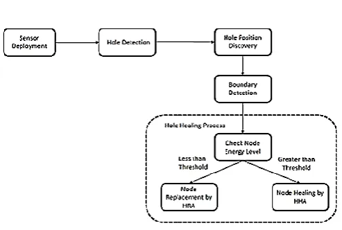
Figure 1. System Architecture
Fig 1 shows system architecture.The fundamental service provided by a Wireless Sensor Network is monitoring the region. The main duty of monitoring is sensing the environment and communicating the available information to the base station. However, the occurrence of holes is unavoidable due to the inner nature of Wireless Sensor Network, random deployment, environmental factors, and external attacks. Thus, its primary task is to provide self-organizing mechanism to detect and recover holes. Nodes send beacon signal from this signal the hole occurrence is identified. Then hole is discovered. Based on the energy level the healing process is proceeded. The hole is healed by moving sensor nodes when the energy level is above threshold. Nodes are moved to the place where hole is detected. By moving nodes the packet loss is avoided. Otherwise if the energy level is below threshold the hole is replaced by actor node.
The Hole detection healing and replacement is done in following phases: Topology formation,Hole detection & position discovery, Border detection, Checking Energy level,Hole healing and Hole Replacement.
A.Topology formation
Topology formation is one of the important issue in a wireless sensor network. Wireless sensor network mainly used for monitoring the events such as disaster tactical in military surveillance. It can be placed in regular manner or irregular manner. Deploying sensors irregularly may create holes in sensor networks. Battery consumes the energy of sensors.It is considered that the sensors are randomly distributed over a large target area. Each and every sensors can sense the specified tasks in its sensing range, and communication is done with in transmission range.
B. Hole Detection & DiscoveryDetection
DHD is the algorithm, it detects hole in WSN.Coverage holes may exist in WSNs due to presence of obstacles or invalid sensor nodes in the sensing field. The holes present makes the data routing failure.Suppose a large amount of sensor node are scattered in a geometric region, with the nearby nodes communicating with the each other directly node failure causes great data loss.Failure of node is detected using beacon signals.Nodes transfer beacon signals between them.These signals carry information like energy level,location of node.When this signal is reached to the neighbouring node the neighbouring nodes send acknowledgement back to the node. After receiving acknowledgement data will be routed.If acknowledgement is not received then the neighbouring node is considered as a failed node.
C. Position Discovery
D. Border Detection
Border detection algorithm is distributed algorithm. The boundary nodes are detected , which will launch the hole discovery and the healing process.Nodes located at the boundary of hole is identified by sending messsage.Node which knows the position of the hole sends message to neighbouring nodes.The node whichis receiving this message calculates the distance between itself and the originator.This message is forwarded to the next neighbouring node.This node will again calculate the distance between itself and the originator and passes the message to its neighbour node. In this way the packet will reach the originator back. Now originator will have some nodes with their distance.These nodes are considered as the boundary nodes.
E. Checking Node Energy Level
After getting the boundary nodes surrounding the failure node,the energy level of the node is calculated.Energy level is calculated based on the residual energy of the node.
F. Hole Healing using HHA
Hole healing is done by moving the nearby nodes.Neighbouring nodes with high energy is selected and also the nodes are selected in such a way that its connectivity is not disturbed.Such nodes move a little from their position to recover from failure.
Nodes locomotion facilities to heal detected holes is exploited.Relocation algorithm is completely distributed.A local healing is performed only on the nodes located at an appropriate distance from the hole.
In healing process, the originator will then finds the nodes with minimum distance.Then it will send the healing message to those nodes.Healing message involves the distance of the hole.Nodes receiving this message will move to the particular distance.And by this process the hole is healed.A method proposed works on both energy and distance for giving longer lifetime to the network. Only shortest distance of relocation is considered and the nodes nearer to the holes will be selected or the nodes with maximum energy are selected. A combination of energy and distance is used for hole healing.
First the average energy of all the nodes is calculated, so that the nodes which are having residual energy greater than a threshold value is selected .Then, the hole healing area is calculated so that the nodes could be relocated for effective coverage. Then some movement to hole healing area is given such a way that the nodes gets relocated . The proposed method selects the next node to be relocated by utilizing energy in an efficient manner. By doing this, packet dropping rate decreases.
G. Hole Replacement Using HRA
Hole Replacement Algorithm after finding the energy level is below the threshold level,the hole has to be replaced by actor node.
When the energy level is below the threshold the low energy nodes ids are passed to the base station.Base station then sends the id to actor node and instruct the actor node to move to the corresponding position.
Actor node after receiving the position moves to instructed position.Now the failure node is replaced by the actor node.Data now passes through the path where the node is replaced.
III.
RESULTS AND DISCUSSION
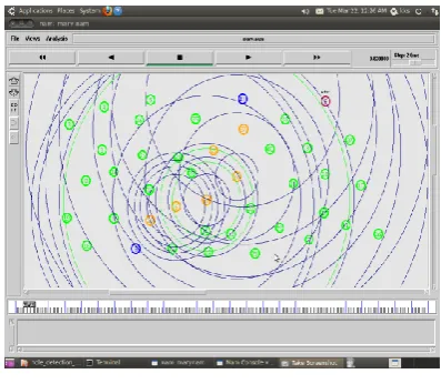
Figure 2. Node Deployment
Figure 3. Data transfer between source and base station
Fig 3 illustrates data transfer between source and base station. Before sending data, source sends its corresponding energy level, location information to the neighbouring nodes through beacon signals. Neighbouring nodes upon receiving the signal has to send back acknowledgement to the source. Only after receiving acknowledgement data transfer takes place between nodes.
Figure 4. Detection of Energy Loss
Fig 4 indicates energy loss of the node. While transferring data between source and destination the energy of the gets reduces.
Figure 5. Failure Detection
Fig 5 illustrates failure detection. Red color indicates dead node. Failure of node is detected by beacon signals when the nodes does not send back acknowledgement.
Figure 6. Hole Healing
Fig 6 illustrates Hole healing. When failure occurs boundary nodes are detected by forwarding packets. Then energy level of the boundary node is checked. Boundary nodes are illustrated as the yellow green circle. When the energy level is above threshold neighboring nodes are moved to heal the node failure.
Figure 7. Node Replacement
Figure 8. Comparison of number of nodes moved
Fig 6 illustrates comparison of nodes moved in existing and proposed system. Numbers of nodes are plotted along the x-axis and count is plotted along y-axis. It is clearly shown that the number of nodes moved in proposed system to heal failure is less compared to the existing system. Hence the energy consumption will be low in the proposed system compared to the existing system
Figure 9. Comparison of packet loss
Fig 7 shows packet loss comparison between existing and proposed system.Time is plotted along x-axis and packet size is plotted along Y-axis.Packet loss is caused because of node failure. By using HHA algorithm the failure is detected and healed quickly. Hence packet loss is minimized compared to the existing system.
IV.
CONCLUSION AND FUTURE WORK
Detection healing failure and node replacement is an important aspect in WSN. Hole detection healing and replacement algorithm used increases network lifetime to make efficient network connectivity for data transmission. Failure is healed by moving neighbouring
nodes from higher density area. It involves minimum relocation of nodes. So the energy consumption of the nodes is relatively low. The failure is detected and healed efficiently which reduces the packet loss.
To reduce the energy consumption actor node is placed in the place of failed nodes. When the neighbouring nodes have low energy level
actor node is used in
place of failed node.
V.
REFERENCES
[1] Ammari H.M. and Das S.K. (2012), „Centralized
and clustered k-coverage protocols for wireless sensor networks‟, IEEE Trans. Comput., vol. 61, no. 1, pp. 118–133.
[2] Bai X., Yun Z., Xuan D. and Lai T.H. (2010),
„Optimal patterns for four connectivity and full coverage in wireless sensor networks‟, IEEE Trans. Mobile Comput., vol. 9, no. 3, pp. 435–448.
[3] Gupta H., Zhou Z., Das S.R. and Gu Q. (2006),
„Connected sensor cover:Self-organization of
sensor networks for efficient query
execution‟,IEEE/ACM Trans. Netw., vol. 14, no. 1, pp. 55–67.
[4] Ma C., He J., Chen H.H. and Tang
Z.(2013),„Coverage overlapping problems in applications of IEEE 802.15.4 wireless sensor networks‟, in Proc. IEEE Wireless Commun. Netw. Conf., pp. 4364–4369.
[5] Mahboubi H., Habibi J., Aghdam A.G. and
Sayrafian-Pour K. (2013), „Distributed deployment strategies for improved coverage in a network of mobile sensors with prioritized sensing field‟, IEEE Trans. Ind. Informat., vol. 9, no. 1.
[6] Megerian S., Koushanfar F., Potkonjak M. and
Srivastava M.B. (2005), „Worst and best-case coverage in sensor networks‟, IEEE Trans. Mobile Comput., vol. 4, no. 1, pp. 84–92.
[7] Ram S.S., Manjunath D., Iyer S.K. and
Yogeshwaran D. (2007), „On the path coverage properties of random sensor networks‟, IEEETrans. Mobile Comput., vol. 6, no. 5, pp. 494–506.
[8] Razafindralambo T. and Simplot-Ryl D.(2011),
[9] Shiu L.C., Lee C.Y. and Yang C.S. (2011), „The divide-and-conquer deployment algorithm based on triangles for wireless sensor networks‟, IEEE Sensors J., vol. 11, no. 3, pp. 781–790.
[10] Tseng Y.C., Chen P.Y. and Chen W.T. (2012),
„k-Angle object coverage problem in a wireless sensor network‟, IEEE Sensors J., vol. 12,no. 12, pp. 3408–3416.
[11] Wang G., Cao G. and Porta T.F. (2006) ,
„Movement-assisted sensor deployment‟, IEEE Trans. Mobile Comput., vol. 5, no. 6, pp. 640–652.
[12] Wang X., Han S., Wu Y. and Wang X. (2013),
„Coverage and energy consumption control in mobile heterogeneous wireless sensor Networks‟, IEEE Trans. Autom. Control, vol. 58, no. 4, pp. 975–988, Apr. 2013.
[13] Wu J. and Sun N. (2012) „Optimum sensor density
in distortion-tolerant wireless sensor networks‟, IEEE Trans. Wireless Commun., vol. 11, no. 6, pp. 2056–2064, Jun. 2012.
[14] Yang S., Li M. and Wu J. (2007), „Scan-based
movement-assisted sensor deployment methods in
wireless sensor networks‟, IEEE
Trans.ParallelDistrib. Syst., vol. 18, no. 8, pp. 1108–1121.
[15] Zhang C., Bai X., Teng J. and Xuan D. (2010),
„Constructing low-connectivity and full-coverage three dimensional sensor networks‟, IEEE J. Sel. Areas Commun., vol. 28, no. 7, pp. 984–993.
[16] Shahram Babaie1 and SeyedSajadPirahesh, “Hole
Detection for Increasing Coverage in Wireless SensorNetwork Using Triangular Structure”, IJCSI International Journal of Computer Science Issues, Vol. 9, Issue 1, No 2, January 2012 ISSN (Online): 1694-0814 www.IJCSI.org
[17] FarhadNematy and NaeimRahmani,”Using
Voronoi Diagram and Genetic Algorithm to Deploy Nodes in Wireless Sensor Network”, JSCSE, Vol. 3, No. 3, Special Issue: [SCSE‟13], San Francisco,
CA, U.S.A., March 2013 Doi:
10.7321/jscse.v3.n3.107 e-ISSN: 2251-75.
[18] Rajat Bhardwaj and Hitesh Sharma, “Holes in
Wireless Sensor Networks”, Lovely Professional
University, Phagwara, Punjab, India,