Achieving Inter-domain Routing Security Based on
Distributed Translator Trust Model
Lingjing Kong1,3and Hong Shen2,3 1 School of Information Science and Technology,
Southwest Jiaotong University, China [email protected] 2
School of Information Science and Technology, Sun Yat-sen University, China
School of Computer Science University of Adelaide, Australia
Abstract. To resolve the difficulties in deployment of the classic security solution S-BGP (Secure Border Gateway Protocol), the Translator Trust Model (TTM) for a new solution SE-BGP (Security Enhanced BGP) was proposed to transform the centralized deployment mode of S-BGP to distributed mode. However, the trust (at-testations of routing information) translation of TTM only depends on a single hub node and this results in severe threats for the inter-domain routing system. To over-come the deficiencies of TTM, in this paper we improve TTM to Distributed TTM (DTTM) by expanding the single hub node to a set of selected multiple hub nodes; in our DTTM, the task of attestations is distributed over multiple hub nodes instead of on a single hub node. In order to make the hub nodes respond to the case of single node failures, we design a restoration mechanism to recover the network based on the neighbour-ring structure. Besides, we develop Cooperative Secure BGP (CS-BGP) to realize DTTM in BGP. In comparison with SE-BGP, our experimental results show that CS-BGP achieves an improved scalability, reduced convergence time and enhanced security.
Keywords:BGP security, TTM, DTTM, restoration mechanism, CS-BGP.
1.
Introduction
A number of self-governed Autonomous Systems (ASs) constitute the Internet. In such a system, routing messages in the interior of an AS are forwarded by a single or multiple Interior Gateway Protocol (IGP), while among ASs they are carried by Border Gateway Protocol (BGP) [1]. In fact, BGP always serves as an indispensable bridge to realize communication among different ASs. However, at the beginning of BGP design, every AS is considered as a trust entity, so there is no security mechanism for BGP. Also, due to the important role of BGP, its security has been drawn much attention by attackers. Thus, BGP is very vulnerable, which directly influences the availability of entire network.
order to solve the above problems, many approaches have been proposed. Secure BGP (S-BGP) [2] is the most classic, comprehensive and rigor solution in the area of BGP security. However, the centralized authentication mode and the way of “onion validation” lead to difficult deployment in the actual network. To address this problem, a series of improved solutions were proposed, but none of them has solved the problem completely. In 2007, Hu et al. [3] put forward a Trust Translator Model (TTM), and then in 2012, proposed the scheme realizing TTM in BGP called Security Enhance BGP(SE-BGP) [4]. Through decentralizing the centralized authentication mode of S-BGP to different self-organized AS alliances, the TTM indeed improves the ability of deploying the PKI, the scalability, and reduces the computational burden. However, the trust translation among AS alliances only depends on a single hub node. This will bring in too much traffic on the single hub node, causing the problem of network bottleneck and network breakdown due to the sin-gle node failure. The deficiencies of TTM motivate us to distribute the tasks of attestations from a single hub node to multiple hub nodes, hence extending TTM to Distributed TTM (DTTM). We first design a distributed multi-hub structure (DMHS) by partitioning an AS alliance into multiple sub-groups centred on multiple hub nodes. Based on DMHS, we build the DTTM which employs multiple hub nodes to implement trust translation among AS alliances and provide rescues in the case of hub node failures. Besides, we propose a new Cooperative Secure BGP (CS-BGP) by embedding DTTM into BGP. The experi-mental results show that CS-BGP solves the security problems of SE-BGP, and as well as improves the scalability and convergence performance.
The rest of paper is organized as follows: the first section introduces the related work in recent years and studies the existing solutions; Section 2 illustrates the principle of the TTM and discusses its deficiencies; Section 3 states the principle of our model – DTTM in detail; Section 4 introduces the recovery mechanism for hub nodes failures; Section 5 gives the approach of DTTM realization on BGP; Section 6 presents the results of experiments and analysis; Section 7 concludes the paper.
2.
Related Work
In order to address the security problems in BGP, two methods are proposed recently: One is to detect the abnormal messages to guarantee the security of BGP; The other is to adopt cryptographic technologies to prevent BGP from attacked.
to find that in this type, all these are just detective not preventive methods, thus too weak in terms of the security. In addition, the detection usually returns a result of high false positives and false negatives.
Compared with the first type, the second type uses the active ways and cryptographic techniques to provide higher security, which has become a main method. In this type, S-BGP is the earliest, most classic and integrated security solution so far. However, its “hierarchical” authentication mode and “onion” attestation manner cause the global PKI deployment obstacle, poor scalability and high computational overhead. In 2003, soBGP [10] was designed by Cisco to make up for the deficiencies of S-BGP. soBGP adopts a more flexible “trust web” authentication mode to replace the centralized mode in S-BGP; The path attestations are implemented only through the consistency with a static topology database, which posts another potential vulnerability to the system. Then in 2007, psBGP [11] came out for in search of balance between the security and the feasibility to cover the shortage in S-BGP. psBGP employs a distributed assertion prefix list (PAL) to authenti-cate the IP prefix owner instead of the hierarchical PKI in S-BGP, but this way lowers the security of IP prefix authentication. The verification of path attestation is still processed by the hierarchical PKI, which contradicts the adoption of the PAL instead of the PKI. HC-BGP[12], FS-BGP[13] are also the follow-up work of S-BGP. HC-BGP attempts to use the hash chains to alleviate the burden of global PKI. However, whether the solution can protect BGP without PKI is doubtful. On the contrary, the authors of FS-BGP believe that the PKI is essential in BGP security solutions, so to improve the feasibility of S-BGP, FS-BGP chooses the way to reduce the cost of attestations and verifications rather than to solve the problem existed in deploying the centralized PKI. In recent years, another hot topic in this area is RPKI[14] – a new security infrastructure designed for supporting S-BGP or soBGP. But it is still controversial because it depends on the centralized author-ities and posts a potential risk[15]. We have to acknowledge that though the research on BGP security has experienced more than ten years, no solution has been widely deployed in the real world[16][17]. The deployment of BGP security solutions still face the big challenges.
In fact, there are three obstacles in deploying BGP security solutions in the actual network:
– The deployment of the centralized hierarchical PKI for authentication and certificates management.
– The high computational overhead of processing signatures and verifications.
– The transition from BGP to adopting BGP security solutions [18] [19].
with the case of single node failure. By employing DTTM in BGP, a security protocol CS-BGP is then developed.
3.
Trust Translation among AS alliances
3.1. AS alliance
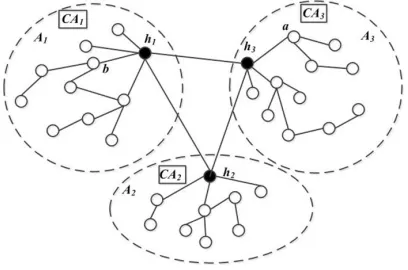
AS network topology can be seen as an undirected graph. Every AS is regarded as a node, while the connections between any two ASs are the edges in the graph. According to the rich-club characteristic [20] of the AS network topology, the concept of AS alliance [3] is defined that it is a group of nodes organized by themselves and connected to the nodes in other AS alliances by minority nodes; The minority nodes derived from rich-club nodes are called hub nodes serving as a communication bridge among AS alliances. In [21], the algorithm of generating AS alliances is presented in two steps: Firstly, confirm the hub node from rich nodes (generally larger ISPs) as the initial node for an AS alliance; Then add the non-hub customer nodes of the hub node to the AS alliance. If the added nodes still have non-hub customer nodes, continue addition until there are no nodes to add. The structure can be seen in Fig. 1:
Fig. 1.AS alliance structure
In Fig.1,A1,A2,A3are three different AS alliances;h1,h2,h3are hub nodes ofA1,A2,A3 separately being responsible for communication amongA1,A2andA3.
3.2. The Trust Translator Model (TTM)
Model principle. Prior to introducing the priciple of TTM, we first give two functions:
1. Sigx(y): the signature of informationybyx.
2. V erx(y): the verification of signature informationybyx.
nodes in different AS alliances can’t identify the certificates for each other except the hub nodes; hub nodes hold the certificates issued by CAs both in local AS alliances and foreign AS alliances because of their special identities and functions. Let’s take an example to illustrate the principle of the TTM, as shown in Fig.1. If nodebinA1advertises an update messagem, and reaches nodeathrough the pathb-h1-h3. Then:
Firstly, b signs m using the private key held by itself and forwards to hub node
h1. h1 can easily get the certificates of b from CA1 and verify the signature utiliz-ing the public key derived from the certificates. If V erh1(Sigb(m))succeeds, it
gen-erates Sigh1(mb−h1) using the private key distributed by CA3 and sends it to h3. If
h3 performs the verification of Sigh1(mb−h1)using the certificates from CA3 and of
Sigb(m)using the certificates fromCA1successfully, it will produceSigh3(mb−h1−h3),
and then transmits toatogether withSigh1(mb−h1). Finally,acompares the consistency
ofV era(Sigh1(mb−h1)),V era(Sigh3(mb−h1−h3))andmto decide whether to receive
the information and updates the routing table. If the result is not inconsistent, it discards the message.
Deficiencies. From the principle of the TTM, we can discover that as the unique hub node in AS alliance, it is regarded as a trust entity to translate the attestation information for all normal nodes in the same AS alliance. So, the single hub node is extremely easy to become the bottleneck point to affect the performance of the network. Also once the fail-ure of single hub node happens, it might paralyse the network without any corresponding measures. Hence, in this paper, we propose the DTTM to overcome the deficiencies in TTM.
4.
Distributed Trust Translation
4.1. Clustering feature in AS Network
It was observed in [22][23] that an AS network is composed of multiple clusters. Usually, there are two metrics to measure these clusters: size and SCM (Scaled Coverage Measure). Size refers to the number of AS nodes in a cluster; SCM is a standard that evaluate the significance of a cluster, which is proportional to the size. Commonly, the communication among the nodes in different clusters is achieved through a center node. The hub node is infact the center of the cluster with the maximum size and SCM to take charge of messages forwarding and trust (signatures) translations among AS alliances.
In view of analysis above, we can find that there exist other clusters with smaller sizes and SCMs besides the biggest cluster gathered by Original Hub Node (OHN). Besides, the hub nodes are not just the hub of clusters, but ISPs of other normal nodes in the same cluster; The normal nodes are affiliated to the ISP node as their customers.
So, based on the above analysis, in our model, an AS alliance is partitioned intok
4.2. Distributed Multi-hub Structure (DMHS)
Firstly, we give a method to select multiple hub nodes within an AS alliance Ai(i =
1,2, ..., n). Supposing the number of selected hub nodes is a given valuek(k= 2,3, ..., n), instead of a single hub node,khub nodes will serve as “translators” to undertake the de-livery of update messages among AS alliances.
Hub nodes selection. An AS network can be represented as a graphG= (V, E):V =
{vi|i= (1,2, ..., n)}denotes the set of all AS nodes;E ={ei |i, j = (1,2, ..., n), i6=
j}denotes the edges between any two nodesvi.dvidenotes node degree, that is the total numbers of edges connected to a nodevi.
Implementation steps:
1. Cluster partition: Firstly, in the generated topology graphGAi = (VAi, EAi)ofAi, employ the existing partition algorithm to getmclusters with different sizes and SCM values, denoted asClAi.
ClAi ={clAi−1, clAi−2, ..., clAi−m}
2. Confirm the hub nodes of the clusters: For any clusterclAi−x, the hub node is the node with the maximum node degree. If usehAi−mrepresents the hub node of the
mth cluster, then,
hAi−m=max(dvi)
In this way, we can selectmhub nodes and get a setHubAi ={hi−1, hAi−2, ..., hAi−m}.
Sub-groups generation. Cluster distancedist(x, y): It refers to the distances between two clusters in the same AS alliance. Forx, y ∈clAi, there is
dist(x, y) =min{dist(hAi−x, hAi−y)}
Implementation steps:
1. According to the size or SCM of the cluster, sort all the elements ofClAi in a de-scending order and get a new setCl0A
i ={cl 0 Ai−1, cl
0
Ai−2, ..., cl 0 Ai−m}. 2. Selectkmaximum clusters, denoted asgAi−1(0), gAi−2(0), ..., gAi−k(0). 3. Remove the selectedkclusters, we can get a new set
ClA00i ={cl0A
i−(k+1), cl 0
Ai−(k+2), ..., cl 0 Ai−m}. For every element inCl00A
i, implement the following algorithm:
∀p= 1,2, ..., k,q= 1,2, ..., k,p6=q;x= (k+ 1), ..., m;
Ifdist(cl0Ai−x, gAi−p(0))< dist(cl 0
Ai−x, gAi−q(0))
clA0i−x∈gAi−p
Confirmation of hub nodes of sub-groups. IfH0Ai is the set of all hub nodes of sub-groups, then
H0Ai={h 0
Ai−1, h 0
Ai−2, ..., h 0
Ai−k}
That is,khub nodes are separately the hub nodes ofgAi−1(0), gAi−2(0), ..., gAi−m(0).
Connection among hub nodes. The connection among multiple hub nodes should meet the following two conditions:
1. Maximize the efficiency of routing messages transmission among multiple hub nodes with low cost;
2. Minimize the impact of the failures and rapidly recover the interrupted network in the event of hub nodes failures.
If we only consider the first condition, a full-mesh structure would be the best choice. Since the number of hops between any two hub nodes is only one, the transmission of messages can be delivered most efficiently. However, the following deficiencies exist in the full-mesh structure:
– The number of connections grows as the square of the number of hub nodes, which deteriorates the scalability of the structure;
– The storage of certificates on hub nodes expands as the increase of connections among hub nodes;
– (k−1) nodes and link failures caused by the failure of a single node can trigger routing oscillations, resulting in the extra cost of routing table updates, packet losses, and hence worsen the network performance.
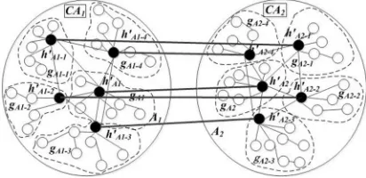
Fig. 2.Structure of DMHS
In view of the defects discussed above, considering k is normally given a bigger value(k > 4), we construct a two-level ring, where OHN locates at the first level ring and other hub nodes form the second ring centred on OHN. Though in comparison with the full mesh, the numbers of hops increase to two at most, it improve other aspects:
– The storage of certificates on hub nodes can be decreased;
– The number of impacted hub nodes except OHN is reduced from 1 tok−31.
Besides, the second type structure is more consistent with the actual network. There-fore, for k > 4 (normally, k is definitely greater than 4), we adopt a two-level ring to better meet the demands of DMHS. The structure of DMHS can be seen in Fig.2.
4.3. The Distributed Translator Trust Model (DTTM)
Certificates distribution. In DTTM, regardless of intra- or inter-alliance, the trust trans-lation can’t be accomplished unless holding the related certificates. So, we will firstly specify how to distribute the certificates.
Suppose there are two AS alliancesAi,Aj;gAi−x is a sub-group inAi andgAj−y is its directly conncected subgroup inAj.CAi andCAj are the authorities to issue the certificates inAi andAj respectively. As the translator among AS alliances, each hub node in Ai andAj holds the certificates issued by both CAi andCAj. The rules of certificates distribution are:
– Intra-alliance: The normal nodes ingAi−xhold the certificates of nodes in the same sub-group and of hub nodes in the directly connected sub-groups. The hub node of
gAi−xholds the certificates of all nodes in the same sub-group and of all the nodes in the directly connected sub-groups.
– Inter-alliances: All the normal nodes ingAi−x hold the certificates of hub node of
gAj−j. The hub node ofgAj−xholds the certificates of all the nodes and neighbours of the hub node inAj.
The DTTM principle. Different from TTM, Multiple hub nodes work collaboratively to achieve the translation of trust both in intra- and inter- AS alliances. We will illustrate the principle of DTTM through an example. Assuming a is a normal node ingAi−x,
b is a normal node ingAj−p; they connect to each other throughgAj−y.h 0 Ai−x,h
0 Aj−p andh0A
1. ageneratesSiga(m)and sends toh0Ai−x;
2. Ifh0Ai−xperformsV erh0Ai−x(Siga(m))successfully;
3. h0Ai−x generatesSigh0Ai−x(ma−h0Ai−x)(*use private key distributed byCAAj*) and sends toh0Aj−y together withSiga(m);
4. If h0Aj−yperforms V erh0Aj−y(Sigh 0
Ai−x(ma−h 0
Ai−x)) (*use certificates granted by CAAj*) && V erh0
Aj−ySiga(m) successfully (*use certificates granted by
CAAi*);
5. h0Aj−y generates Sigh0Aj−y(ma−h0Ai−x−h0Aj−y) and sends it together with
Sigh0
Ai−x(ma−h0Ai−x)toh
0
Aj−p;
6. If h0Aj−p performs V erh0Aj−p(Sigh 0
Ai−x(ma−h 0
Ai−x)) &&
V erh0
Aj−p(Sigh0Aj−y(ma−h0Ai−x−h0Aj−y)) successfully (*both use certificate granted byCAAj*);
7. h0Aj−pgeneratesSigh0Aj−p(ma−h0Ai−x−h0Aj−y−h0Aj−p)and sends it together with
Sigh0
Aj−y(ma−h 0 Ai−x−h
0
Aj−y)tod; 8. If d performs V erd(Sigh0
Aj−y(ma−hAi0 −x−h0Aj−y)) &&
V erd(Sigh0
Aj−p(ma−h 0 Ai−x−h
0 Aj−y−h
0
Aj−p)) successfully (*both use certifi-cate granted byCAAj*);
9. ma−h0 Ai−x−h
0
Aj−y =V erd(Sigh 0
Aj−y(ma−h 0 Ai−x−h
0 Aj−y)); 10. ma−h0
Ai−x−h0Aj−y−hAj0 −p=V erd(Sigh0Aj−p(ma−h0Ai−x−h0Aj−y−h0Aj−p)); 11. Ifma−h0
Ai−x−h0Aj−y =ma−hAi0 −x−h0Aj−y−h0Aj−p=m 12. Done;
5.
Recovery of hub node failures in DTTM
In this section, we propose a recovery scheme based on the hierachical neighbour-rings (NRs) to provide timely recovery for any single hub node failure. In the fourth part of Section 4.2., we have constructed a two-level ring. Then we construct the third-level logic ring consisting of the neighbours of the hub nodes on the second ring. To identify their levels in NRs, we assign each node an unique hierarchical ID number. Every node on NRs selects the backup nodes for their centric nodes, and stores them in local tables in advance. Once a node detects a failure, it can immediately find the appropriate nodes from the table to take over the work of the failed node. It can be seen that because the backup nodes have been selected and stored before the occurrence of the failure, the large amounts of consumption on time and costs can be avoided in the process of the recovery. The mechanism mainly includes two stages: precovery preparation and failure re-covery process.
5.1. Pre-recovery preparation
Before the recovery of a hub node failure, we take three steps for pre-recovery preparation:
N Ri =SN ei(c, j)
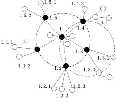
There are totally three-level NRs: The first-level NR is OHN itself; The second-level NR is constructed by the neighbours of OHN; The third-level NRs are constructed by the neighbours of the nodes on the second-level ring.
2. ID number allocation for nodes on NRs. To identify the level of the nodes in all NRs, every node should be allocated an unique hierarchical ID number. The hierarchical ID number is consisted of two parts: prefix and suffix. They are separated by a dot. The prefix represents the number of centric node; the suffix represents the sequence number on the NR of the centric node. All the sequence number of suffix on the ring is arranged in an ascending order. As shown in Fig.3, “1” is the ID number of OHN; “1.3” is on the NR with the center at “1” and a sequence number “3”; “1.3.1” is on the NR with the center at “1.3” and a sequence number “1”.
Fig. 3.NR recovery structure
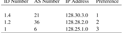
node degrees and give this nodes a lower preference. If this node is a hub node, it stores NLL-BNT and LL-BNT; Otherwise, stores NLL-BNT. Table 1 is an example of NLL-BNT.
Table 1.NLL-BNT
ID Number AS Number IP Address Preference
1.4 21 128.30.3.0 1
1.2 36 128.28.2.0 2
1 6 128.25.1.0 3
5.2. Failure recovery process
1. Failure detection. Let us suppose there is a heartbeat mechanism for the members on each NR. In a real network context, this can be easily realized by “keep alive” messages of BGP. By periodically sending heartbeat messages, it is not difficult to detect failures. Define detection functionD(neij)for allnei(c, j), j= 1,2, ...t:
– Ifcis down, there is no response for heartbeat messages, thenD(nei(c, j)) = 0
and look for the backup nodes from BNT.
– Ifnei(c, j)receives the reply fromc, then there is nothing wrong withc,D(nei(c, j)) = 1.
2. Confirmation of the replacement node. If the result of implementation onD(neiy), a normal nodenei(c, y)(j= 1,2, ..., t)gets, is 0, then
– Stop sending heartbeat message toc.
– For i = 1(i = 1,2, ..., n) (i = 1 is the first item in N LL−BN Ty, also with the maximum preference), extract the information ofiand connects with
nei(c, x)(x= 1,2, ..., t)(nei(c, x)is the corresponding node withi).
– If nei(c, i)(i = 1,2, ..., t)is not down, confirm it as the replacement for the failure node; else,i++, return the second step.
3. Start-up failure recovery. For a normal node, modifies the routing information of the failed node in the routing table and keeps connection with the replacement node. For a hub node, extracts every items fromLL−BN T and makes connections with them; Then updates the routing table.
6.
Embedding DTTM into BGP
In this section, we propose an approach called CS-BGP to embed DTTM into BGP. Sim-ilar with S-BGP, the data of CS-BGP is carried on two optional, transitive attributes of BGP update message:AS Source EvidenceandAS Route Evidence.
AS Source Evidencestores the signatures of IP address prefixes, which indicates whether the original AS has right to announce the IP address prefixes;AS Route Evidence
functions between hub nodes and normal nodes, the principles are also different. In our scheme, multiple hub nodes indeed are the ISPs of different levels; they themselves are more powerful in process ability and security, but they are possibly to suffer attacks. In this case we can consider designing a monitor system for multiple hub nodes to supervise mutually. But here, we suppose all hub nodes are not exposed to attack and trusted by other nodes. Next we will introduce how CS-BGP works.
6.1. Realization on hub nodes
Assumingh0A
i−xis the hub node ofgAi−xinAi,|AS P AT H|isn(AS P AT His an important attribute of BGP update message, which indicates the path of AS during the process of message transmitting), the number of elements inAS Source Evidenceisp, then the algorithm of realization on hub nodes is as follows:
Input: update messagem,AS Source Eveidence,AS Route Evidence. 1. Whenh0Ai−xreceivesm
GetsAS Source Evidence[0]and validates; 2. If the result is correct
GetsAS Route Evidence[0], ...,AS Route Evidence[p]and validates; 3. If the result is correct
AddsASn+1toAS P AT H;
Generates the signature for the signed information {IPP ref ix, ASn+1, ASn, ..., AS0, ASn+2};
4. Ifmcomes from a normal node
Adds the signature toAS Route Evidence[p+ 1]; Ifmcomes from a hub node
DeletesAS Route Evidence[0], ...,AS Route Evidence[p−1]; DeletesAS Source Evidence[0];
Adds the signature toAS Route Evidence[1]; 5. Updates the routing table;
SendsmtoASn+2.
6.2. Realization on normal node
Input: update messagem,AS Source Eveidence,AS Route Evidence; 1. When a normal nodecreceivesm
Ifcand the source node are in the same sub-group GetsAS Source Eveidence[0]and validate; If the result is correct
Go to 2;
Else direct go to 2;
2. GetsAS Route Evidence[0], ...,AS Route Evidence[p]and validate; 3. If the result is correct
AddsASn+1toAS P AT H;
Generates the signature for the signed information
{IPpref ix, ASn+1, ASn, ..., AS0, ASn+2}; 4. Update the routing table;
7.
Experiment and Analysis
7.1. Security
Our work aims at solving the problems of network traffic bottleneck and single node failures.
For the first problem, we apportion the tasks of attestations on a single hub node in AS alliance tokhub nodes. So, the burden on the single hub node can be reduced to 1k. The result depends on the value ofk. Thus, the greaterkis, the more bottleneck effect reduces.
For the second problem, the cooperation of multiple hub nodes can avoid the single node failure and the normal communication among AS alliances. Besides, the neighbours of each hub node store the selected backup nodes in advance. Thus, when a single hub node fails, the neighbours can quickly find the replacement node and extract the related information, then switch the routing messages to it. In general, the default time of heart-beat is 60 seconds, the time of BGP session establishment is around tens of milliseconds. So the time of recovery will be limited to an acceptable range.
7.2. Scalability
Suppose the number of AS nodes in every AS alliance is the same; the number of AS nodes in every sub-group is also the same. The following experiment will compare SE-BGP with CS-SE-BGP in the number of certificates and analyze the scalability of the two models. Firstly, we introduce some related notations, as shown below:
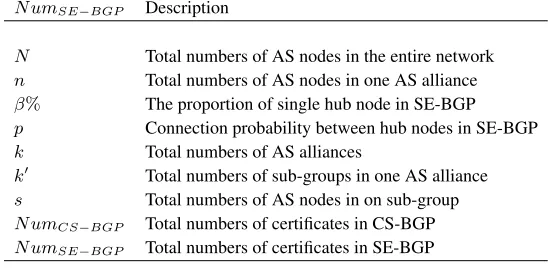
Table 2.Related notations
N umSE−BGP Description
N Total numbers of AS nodes in the entire network
n Total numbers of AS nodes in one AS alliance
β% The proportion of single hub node in SE-BGP
p Connection probability between hub nodes in SE-BGP
k Total numbers of AS alliances
k0 Total numbers of sub-groups in one AS alliance
s Total numbers of AS nodes in on sub-group
N umCS−BGP Total numbers of certificates in CS-BGP
N umSE−BGP Total numbers of certificates in SE-BGP
From Table 2, we know,
k=N· 100β ;n= N N·β% =
100 β ;s=
n
k0 =β·k1000. Then, total numbers of certificates held by normal ASs:
N umCS−BGP = (s2·k0+ 3s·(k0−1) +s(k0−1) +s·p·k·k0)·k= N·β·k1000 + 4N(k0−1)
k0 + β 100·p·N
N umSE−BGP = 100β ·N+ β 100·p·N
2 Total numbers of certificates held by hub nodes:
N umCS−BGP = (3s·(k0−1)+s(k0−1)+((s+3)·(k0−1)·+(s+k0−1))·p·k)·k= 4N(k0−1)
k0 + β 100·p·N
2+4p·β2·N2·(k0−1) 1002
N umSE−BGP = 100β ·p·N 2
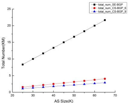
Total numbers of certificates held by all nodes:
N umCS−BGP = N·β·k1000 +
4N(k0−1) k0 +
β
100 ·p·N
2+4N(k0−1) k0 +
β
100 ·p·N 2 = N·100
β·k0 +
8N(k0−1) k0 +
2β 100·p·N
2+4p·β2·N2·(k0−1) 1002
N umSE−BGP = 100β ·N+1002β ·p·N2
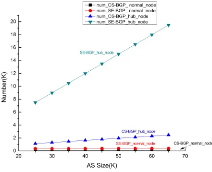
Maximum numbers of certificates held by single normal node:
N umCS−BGP =s+ (k0−1) +p·k= β·k1000 + (k0−1) + p·N·β
100
N umSE−BGP =n+p·k= 100β + p·N·β
100
Maximum numbers of certificates held by single hub node:
N umCS−BGP = (k0−1)·(s+ 1) +p·k·s= (k0−1)·(β·k1000 + 1) + p·N
k0
N umSE−BG=p·N
Here, letβ = 0.3,p = 0.3. As the network scale grows, the number of certificates also increases; the comparison of certificates numbers can be seen in Fig. 4 and Fig. 5. From the graphs we can conclude that in two cases, the certificate numbers of DTTM are both smaller than that of TTM. Besides, Fig.4 compares the case ofk0= 6withk0= 9. It is easy to see ask0increases, the number of certificates decreases and the scalability gets better.
Fig. 5.The number of the certificates hold by single node
7.3. Network convergence
Compared with the original BGP, in SE-BGP and CS-BGP, the network convergence gets worse because of the process of digital signature and validation. In the two solutions, they both adopt the DSA signature algorithm. And the signature time of DSA is about 25.5ms, and the validation time is about 31.0ms [24].
In this section, we employ ns2 [25] to perform the experiment and compare the conver-gence of BGP, SE-BGP and CS-BGP. The first step is using network topology generator BRITE [26] to generate 10 types of BA model topologies three times. The 10 topologies are: 5, 10, 15, 20, 25, 30, 35, 40, 45, 50. Suppose that there is only one router in one AS, the minimum route advertisement interval (MARI) is 30s and the link delay is 1ms.
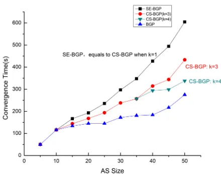
The experiment is designed as follows: a. BGP: Every AS announces one IP address prefix; b. SE-BGP: In 10 topologies, we select two nodes with the maximum node degree as the hub nodes, and divide two AS alliances centred on the hub nodes. Let all the nodes except hub nodes advertise a routing message; c. CS-BGP: First, Partition the AS in each As alliance into 3 sub-groups except the case of in 5,10 topology. Second, Partition the AS into 4 sub-groups when the topologies are 40,45,50. Then, let the ASs announce the Update messages as b. Finally, compute the convergence time of the entire network in the above scenes, and then make comparisons. The results are shown in Fig.6:
From Fig.6 we know that:
1. All curves go up with the increase of AS topology size.
2. Because SE-BGP and CS-BGP both need the process of the signature and the valida-tion, the convergence time must be longer than BGP.
3. In CS-BGP, the traffic is taken by multiple hub nodes instead of a single hub node. So, the network convergence get improved compared with SE-BGP.
4. SE-BGP can be considered as CS-BGP whenk= 1. From Fig.6, we can get that, ifk
Fig. 6.Comparison of convergence time
ofk. In a real network, the size of AS has been over 50000[27], thus, the biggerk
will benefit the convergence of the entire network.
8.
Conclusion
In this paper, we developed a distributed trust translation model DTTM by distributing the tasks of attestations from single hub node to multiple hub nodes. Our DTTM is established by first dividing an AS into multiple sub-groups, and then for each sub-group selecting a hub node taking charge of the tasks of attestations for all nodes within the sub-group. After that we constructed logic NRs to locate the backup nodes for each hub node and assigned an unique ID number for each node in NRs. Each node on NRs selects and stores the backup nodes in advance so as to switch the routing quickly when the failures happen. In addition, we proposed CS-BGP to realize the DTTM in BGP. Finally, the experimental results show that CS-BGP resolves the security deficiencies of SE-BGP and improves network scalability and convergence.
Acknowledgements.This work was supported in part by the Natural Science Foundation of China (61170232), Research Initiative Grant of Sun Yat-Sen University (Project 985) and Ministry of Education Funds for Innovative Groups #241147529. The corresponding author is Hong Shen.
References
1. Rekhter, Y., Li, T., Hares, S. : A Border Gateway Protocol 4(BGP-4). RFC4271.(2006) 2. Kent, S., Lynn, C., Seo, K.: Secure border gateway protocol (S-BGP). IEEE Journal on Selected
3. Hu, X.J., Zhu, P.D., Gong, Z.H.: Translator Trust for the Internet Inter-domain Routing. In: Future Generation Communication and Networking, vol 1, pp. 453-458(2007)
4. Zhu, P.D., Cao, H., Yang, L.T., Chen, K.: AS Alliance based security enhancement for inter-domain routing protocol. Mathematical and Computer Modelling 55(1), 241-255(2012) 5. Zhao, X., Pei, D., Wang, L., Massey, D., Mankin, A., Wu, S. F., Zhang, L.: An analysis of BGP
multiple origin AS (MOAS) conflicts. In: Proceedings of the 1st ACM SIGCOMM Workshop on Internet Measurement. pp. 31-35(2001)
6. Zhao, X., Pei, D., Wang, L., Massey, D., Mankin, A., Wu, S. F., Zhang, L.: Detection of in-valid routing announcement in the Internet. In: Proceedings of International Conference on Dependable Systems and Networks. pp.59-68(2002)
7. Lad, M., Massey, D., Pei, D., Wu, Y., Zhang, L.: PHAS: A Prefix Hijack Alert System. In: Proceedings of the 15th USENIX Security Symposium, vol.15, no 11(2006)
8. Karlin, J., Forrest, S., Rexford, J.: Pretty good BGP: Improving BGP by cautiously adopting routes. In: Proceedings of the 14th IEEE International Conference on Network Protocols. pp. 290-299(2006)
9. Subramanian, L., Roth, V., Stoica, I., Shenker, S.,Katz, R.: Listen and whisper: Security mech-anisms for BGP. In: Proceedings of the 1st Symposium on Networked Systems Design and Implementation, vol. 1. San Francisco, CA(2004)
10. White, R.: Securing BGP Through secure origin BGP (soBGP).The Internet Protocol Journal, vol.6, no.3(2003)
11. van Oorschot, P.C., Wan, T., Kranakis, E.: On inter-domain routing security and pretty secure BGP (psBGP). ACM Transactions on Information and System Security 10(3), no.11(2007) 12. Zhang, Y., Zhang, Z., Mao, Z.M., Hu, Y.C.: HC-BGP: A light-weight and flexible scheme for
securing prefix ownership. In: IEEE/IEIP International Conference on Dependable Systems & Networks. pp. 23-32(2009)
13. Xiang, Y., Shi, X., Wu, J., Wang, Z., Yin, X.: Sign what you really care about-Secure BGP AS-paths efficiently. Computer Networks 57(10), 2250-2265(2013)
14. Lepinski, M., Kent, S.: An Infrastructure to Support Secure Internet Routing. RFC 6480(2012) 15. Cooper, D., Heilman, E., Brogle, K., Reyzin, L., Goldberg, S.: On the risk of misbehaving
RPKI authorities. In: Proceedings of the 12th ACM Workshop on Hot Topics in Networks, No 16(2013)
16. Butler, K., Farley, T. R., McDaniel, P., Rexford, J.: A survey of BGP security issues and solu-tions. In: Proceedings of the IEEE 98(1), 100-122(2010)
17. Goldberg, S.: Why is it taking so long to secure internet routing? Communications of the ACM 57(10), 56-63(2014)
18. Gill, P., Schapira, M., Goldberg, S.: Let the market drive deployment: A strategy for transition-ing to BGP security. In: ACM SIGCOMM Computer Communication Review, vol.41, no.4, pp.14-25(2011):
19. Lychev, R., Goldberg, S., Schapira, M.: BGP security in partial deployment: is the juice worth the squeeze? ACM SIGCOMM Computer Communication Review 43(4), 171-182(2013) 20. Zhou, S., Mondragon, R. J.: The rich-club phenomenon in the Internet topology. IEEE
Com-munications Letters 8(3), 180-182(2004)
21. Xiangjiang, H., Peidong, Z., Kaiyu, C., Zhenghu, G.: AS alliance in inter-domain routing. In: Proceedings of the 22nd International Conference on.Advanced Information Networking and Applications - Workshops. pp. 151-156(2008)
22. Wool, A., Sagie, G.: A clustering approach for exploring the Internet structure. In: Proceedings of IEEE Convention of Electrical and Electronics Engineers in Israel. pp. 149-152(2004) 23. Li, Y., Cui, J. H., Maggiorini, D., Faloutsos, M.: Characterizing and modelling clustering
features in AS-level Internet topology. In: The 27th Conference on Computer Communica-tions(INFOCOM). pp. 271-275(2008)
25. The Network Simulator-ns2,[Online]. Available: http://www.isi.edu/nsnam/ns/(current November 2011)
26. Brite,[Online]. Available: http://www.cs.bu.edu/brite/(current August 2001)
27. University of Oregon Route Views Project, [Online]. Available: http://www.route-views.org/(current May 2015)
Lingjing Kongis a PhD student of Computer Application Technology in Southwest Jiao-tong University, China, and also a joint-PhD student of Com- puter Science in University of Adelaide, Australia. She received her M.Eng degree from Southwest Jiaotong Univer-sity and B.Eng from Lanzhou Jiaotong UniverUniver-sity, China. Her research area is routing security, network protocol and network architecture.
Hong Shenis Professor (Chair) of Computer Science in University of Adelaide, Aus-tralia, and ”1000 People Plan” Professor and Director of Advanced Computing Institute in Sun Yat-Sen University, China. He received Ph.Lic. and Ph.D. degrees from Abo Akademi University, Finland, M.Eng. degree from University of Science and Technology of China, and B.Eng. degree from Beijing University of Science and Technology, all in Computer Science. He was Professor and Chair of the Computer Networks Laboratory in Japan Advanced Institute of Science and Technology (JAIST) during 2001?2006, and Professor (Chair) of Compute Science at Griffith University, Australia, where he taught 9 years since 1992. With main research interests in parallel and distributed computing, algorithms, data mining, privacy preserving computing and high performance networks, he has published more than 300 papers including over 100 papers in international journals such as a vari-ety of IEEE and ACM transactions. Prof. Shen received many honours/awards including China National Endowed Expert of ”1000 People Plan” (2010) and Chinese Academy of Sciences ”Hundred Talents” (2005). He served on the editorial board of numerous jour-nals and chaired several conference.