IJSRSET173295 | Received : 15 March 2017 | Accepted : 28 March 2017 | March-April-2017 [(3)2: 306-310]
© 2017 IJSRSET | Volume 3 | Issue 2 | Print ISSN: 2395-1990 | Online ISSN : 2394-4099 Themed Section: Engineering and Technology
306
Analysis of Shell and Tube Heat Exchanger by using CFD Tool
*J. Sandeep Kumar, RNSV. Ramakanth,
T. Pavan Kumar,
S. Ramakrishna
Vidya Jyothi Institute of Technology, JNTUH, Hyderabad, Andhra Pradesh, IndiaABSTRACT
This paper focuses on the various researches on CFD analysis in the field of heat exchanger. Shell and tube heat exchanger is an indirect contact type heat exchange as it consists of a series of tubes, through which one of the fluids runs. They are widely used in power plant, chemical plants, petrochemical plants and automotive applications. Different turbulence models available in general purpose commercial CFD tools likes’ k-ԑ model, K-ω model and K- ω SST models. Different CFD code available like CFX, FLUENT. The quality of the solution has proved that CFD is effective to predict the behavior and performance of a wide variety of heat exchanger.
Keywords: Shell and Tube Heat Exchanger, CFD computational fluid dynamics, Heat Transfer Characteristics, effectiveness.
I.
INTRODUCTION
A heat exchanger transfers energy from one fluid to another across a solid surface by convection and conduction. Heat exchangers are used in power plants, nuclear reactors, refrigeration and air conditioning systems, automotive industries, heat recovery systems, chemical processing, and food industries. The design of a new heat exchanger (HE) is referred to the sizing problem, means it includes construction type, flow arrangement, tube and shell material, and physical size which has to meet the specified heat transfer and pressure drop rating of existing heat exchanger. We are going to simulate the results for present material of shell and tube heat exchanger and change the material, then compare the results of both and study which is best.
Shell and tube heat exchanger consist bundle of tubes enclosed with in cylindrical shell one fluid pass through the tubes and second fluid flows between the tube and shells. The basic components of a shell and tube heat exchangers are tubes, tube sheets, shell and shell-side nozzles, tube side channels and nozzles, channel covers, pass divider, baffles etc .Most commonly used STHE have large heat transfer surface area-to-volume ratios to provide high heat transfer efficiency in comparison with others. They are mechanically rugged enough to withstand the fabrication stresses and normal operating conditions. They can be easily cleaned and the failure
parts like gaskets and tubes can be easily replaced. They offer greater flexibility of mechanical features to withstand any service requirement. They are manufactured easily for a large variety of sizes and flow configurations. They can operate at high pressures and high temperature. They can be employed for processes which require large quantities of fluid to be heated or cooled. In our case, we have heat exchanger with stainless steel as outer shell and copper as inner tube and baffle plates.
II.
METHODS AND MATERIAL
1. Computational Fluid Dynamics
Computational fluid dynamics, usually abbreviated as CFD, is a branch of fluid mechanics that uses numerical methods and algorithms to solve and analyze problems that involve fluid flows. Computers are used to perform the calculations required to simulate the interaction of liquids and gases with surfaces defined by boundary conditions. The technique is very powerful and spans a wide range of industrial and non-industrial areas.
2. CFD Methodology
During pre-processing
The geometry (physical bounds) of the problem is defined. The volume occupied by the fluid is divided into discrete cells (the mesh). the mesh may be uniform or non-uniform. The physical modelling is defined – for example, the equations of motions + enthalpy + radiation + species conservation
Boundary conditions are defined. This involves specifying the fluid behaviour and properties at the boundaries of the problem. For transient problems, the initial conditions are also defined.
The simulation is started and the equations are solved iteratively as a steady-state or transient.
Finally a postprocessor is used for the analysis and visualization of the resulting solution.
Below figure shows how the total CFD works.
Pre-Processor : Pre-processing consists of the input of a flow problem to a CFD program by means of an operator-friendly interface. The user activities at the pre-processor stage involves geometry clean up, FE modeling like Grid and Cell generation, Selection of the physical and chemical phenomenon that need to be modeled, definition of the fluid properties and specification of appropriate boundary condition at cells.
Solver : Different streams of numerical solution techniques are Finite difference method, Finite element method, spectral method and finite volume method. Following steps will be performed by all the numerical methods.
Different streams of numerical solution techniques are Finite difference method, Finite element method, spectral method and finite volume method. Following steps will be performed by all the numerical methods.
Post-Processor: As in pre-processing a huge amount of development work has recently taken place in the post-processing field. Owing to the increased popularity of engineering workstations many of which have outstanding graphics capabilities, the leading CFD packages are now equipped with versatile data visualization tools.
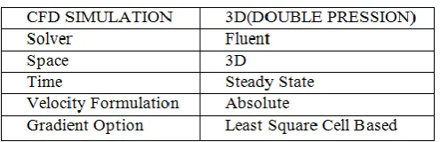
Table 1. Solver Setting
Table 2. Viscous Model and Turbulence Model Settings
Turbulence Model Spalart-Allmaras Spalart-Allmaras 1-equation model Operating Conditions Ambient
Table 3. Boundary condition settings
Table 4. Solution Controls
Fluid Properties Values
Shell side (Exhaust Gas)
Density 0.871 Kg/m3
Specific Heat 0.871j/kg-k Thermal conductivity 0.871w/m-k
Viscosity 0.871kg/m-s
Tube
side(transformer oil)
Density 890 Kg/m3
Specific Heat 2060 j/kg-k Thermal conductivity 0.12 w/m-k
Viscosity 0.01664kg/m-s Velocity
Inlet
Exhaust gas Velocity Inlet
2 m/s
Transformer oil velocity Inlet
0.04, 0.06, 0.09 m/s
Pressure Outlet
Gauge Pressure
magnitude (shell side)
0 Pa
Gauge Pressure
magnitude (tube side)
0 Pa
Wall Zones vehicle surface-no-slip wall B/c
III.
RESULTS AND DISCUSSION
A. Results for the HE without fin with the velocity 0.04m/sec
Figure 1. Pressure distribution for the transformer oil
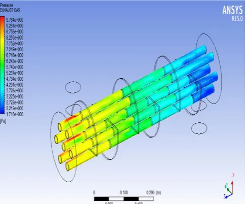
Figure 2. Pressure distribution for the Exhaust gas
Figure 3. Temperature distribution for the Transformer oil
Figure 4. Temperature distribution for the Exhaust gas
B. Results for the HE without fin with the velocity 0.06m/sec
Figure 5. Pressure distribution for the transformer oil
Figure 7. Pressure distribution for the Exhaust gas
Figure 8.Temperature distribution for the Exhaust gas
Figure 9. HE with velocity of 0.04m/s with fin
Fig.10 HE with velocity 0.06m/s with fin
IV.
CONCLUSION
The results which were obtained from the calculations and the graphs that were plotted, were studied very thoroughly and we observe that the effectiveness in general reduces with the increase of the heat exchanger velocities like 0.04,0.06m/s, turbulence models available in general purpose commercial CFD tools likes’ k-ԑ model, K-ω model and K- ω SST models. Different CFD code available like CFX, FLUENT.
V.
REFERENCES
[1]. Master, B. I., Chunangad, K. S.,and Pushpanathan, V., 2003, "Fouling Mitigation
Using Helixchanger Heat
Exchangers,"Proceedings of the ECI Conference on Heat Exchanger Fouling and Cleaning: Fundamentals and Applications, Santa Fe, NM, May 18–22, pp. 317–322
[2]. Bell, K. J., 1981, "Delaware Method for Shell Side Design,"Heat ExchangersThermal Hydraulic Fundamentals and Design, S. Kakac, A. E. Bergles, and F.Mayinger, eds., Taylor & Francis, Washington, DC.
[3]. Bell, K. J., 1986, "Delaware Method of Shell Side Design,"Heat ExchangerSourcebook, J. W. Pallen, ed., Hemisphere, Washington, DC.
[4]. Bell, K. J., 1988, "Delaware Method of Shell-Side Design,"Heat TransferEquipment Design, R. K. Shah, E. C. Sunnarao, and R. A. Mashelkar, eds.,Taylor & Francis, New York.
[5]. Schlünder, E. U., ed., 1983,Heat Exchanger Design Handbook, Vol. 3, Hemi-sphere, Washington, DC
HelicalBaffles," Heat Transfer Eng.,151, pp. 55– 65.
[7]. Schlünder, E. U., ed., 1983Heat Exchanger Design Handbook, Vol. 2, Hemisphere, Washington, DC.
[8]. Gaddis, E. S., and Gnielinski, V., 1997, "Pressure Drop on the Shell Side ofShell-and-Tube Heat Exchangers With Segmental Baffles," Chem. Eng. Pro-cess.,362, pp. 149–159.
[9]. 54Kuppan, T., 2000,Heat Exchanger Design Handbook, Marcel Dekker, NewYork.
[10]. J.P. Holman, Heat Transfer, 9thEdition, McGraw-Hill, 2002.