IJEDR1804025
International Journal of Engineering Development and Research (
www.ijedr.org
)
138
Design Optimization And Dynamic Analysis Of
Composite Leaf Spring Using Fea
Kolli Suribabu, K Sandeepsunandh, G Suneel Kumar 1PG scholar, 2Assistant professor, 3Assistant professor 1,3Guntur engineering college, Guntur, AP-522019, INDIA 2Chebrolu engineering college, Chebrolu, AP-522212, INDIA
_____________________________________________________________________________________________________
Abstract - leaf spring is a simple form of suspension springs, commonly used in automobiles. There are different types of leaf springs and out of those the commonly used type is the semi elliptic type and the two forms of leaf springs that are mainly used under semi elliptic type are multi leaf springs and mono leaf springs. In this project, first a four leaf steel spring is designed by considering the design parameters used in rear suspension of light vehicles and is analyzed. First static analysis is carried out for steel spring. By considering the results of stresses and deflections of steel leaf spring, an optimized composite leaf spring made from fiber glass with epoxy resin i.e. E-glass/epoxy is designed. Main consideration is given to optimization of spring geometry. The main objective is to design a spring with minimum weight and minimum stresses and deflections for the given e x t e r n a l forces. Also the modal analysis is carried out for both the steel and composite springs. Harmonic analysis is also carried out for determining the dynamic behavior for both the steel and composite springs. Transient analysis for both the steel and composite springs is also done for determining the dynamic response under time varying loads. In addition to that four different composite materials like S2-glass/epoxy, carbon/epoxy, graphite/epoxy, boron/aluminium are taken after optimum design and static analysis, modal analysis, harmonic analysis and transient analysis are carried out for all the composite materials and the results are compared for steel and all the composite materials. The main objective is to compare all the results of static analysis, modal analysis and transient analysis for steel and all the composite materials and to conclude which one is best suitable for the leaf spring. It is identified that boron/aluminium and graphite/epoxy are best suitable for the leaf spring.
Keywords - Leaf spring, Epoxy, Carbon, Graphite, Static Analysis, Model Analysis, Transient analysis.
_____________________________________________________________________________________________________
I.INTRODUCTION
Many Innovations in automobile sector and increasing competition tends to modify existing products or replace products with more advanced material products. A vehicle’s suspension system is also an area where regularly the inventions are carried out. Many efforts are taken to enhance the comfort of the user. Comfort riding qualities and economy in manufacturing of leaf spring became an obvious necessity. Introduction of the composite materials has reduced the weight of the leaf spring, and also the stresses and deflections are minimum for the same load carrying capacity i.e. without any reduction on load carrying capacity. Hence, steel leaf springs are being replaced by composite leaf springs.
Main objectives of spring
• To provide cushioning and to absorb or to control the energy due to the shock effects or vibration as in case of car springs and railway buffers, air-craft landing gears, shock absorbers and vibration dampers.
• To apply the forces in case of brakes, clutches and spring loaded valves.
• To control the motion by maintaining necessary contact between the two elements as in case of cams and followers. • To measure forces in case of spring balances, gages and engine indicators.
• To store the energy in case of watches, toys etc.
FINITE ELEMENT METHOD
Finite element method is one of the numerical methods. The basic idea of finite element method is to find the solution of a complicated problem by replacing it by a simpler one. While by replacing the original problem with simpler one, we can only find the approximate solution rather than exact solution. But the finite element is used where there are no tools to find out the original solution of the complex problems. Whether solution is approximation by using more computational efficiency the approximation will be very near to the exact solution. In the present study finite element are used. There are different tools are available to apply numerical methods. Named as ANSYS, Abacus, hyper works...etc. In the present study Ansys is used.
IJEDR1804025
International Journal of Engineering Development and Research (
www.ijedr.org
)
139
• To design a four leaf steel spring and to do the static analysis.• To design an optimized mono composite spring made of E-glass/epoxy based on the results of stresses and deflections obtained for steel spring.
• To analyze the composite leaf spring for stresses and deflections.
• To perform the modal analysis, harmonic analysis and transient analysis for steel and composite springs.
• To take another four different composite materials like S2-glass/epoxy, carbon/epoxy, graphite/epoxy and boron/aluminium and perform the static analysis, modal analysis, harmonic analysis and transient analysis for all the composite materials.
• To compare all the results of static analysis, modal analysis, harmonic analysis and transient analysis for steel and all composite materials and to conclude that which one is best suitable for the leaf spring.
III. FINITE ELEMENT MESHING
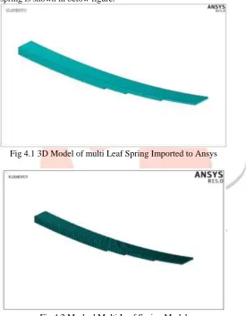
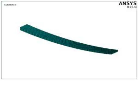
In the process of converting the geometrical entities to finite element entities such as nodes and elements, the multi leaf steel spring was meshed with solid 185 element type. A total number of 13431 nodes and 14050 elements were created. The meshed model of the multi leaf spring is shown in below figure.
Fig 4.1 3D Model of multi Leaf Spring Imported to Ansys
Fig 4.2 Meshed Multi Leaf Spring Model
The 3D model of mono composite leaf spring created in Pro-E is imported to Ansys. The file which is imported to Ansys appears as shown in below figure.
IJEDR1804025
International Journal of Engineering Development and Research (
www.ijedr.org
)
140
In the process of converting the geometrical entities to finite element entities such as nodes and elements, the mono leaf composite spring was meshed with solid 185 element type. A total number of 9372 nodes and 7050 elements were created. The meshed model of the mono leaf spring is shown in below figure.Fig 4.4 Meshed Mono Leaf Spring Model Material properties
Along with steel, five different composite materials like E- glass/epoxy, S2-glass/epoxy, carbon/epoxy, graphite/epoxy and boron/aluminium are taken in the present work. All the composite materials are assigned with the following material properties that are shown in below table.
Material Property
E-glass/ Epoxy
S2glass/ Epoxy
Carbon/ Epoxy
Graphite/ Epoxy
Boron/ Aluminium
E1 27700 22200 142000 142600 215000
E2 8400 20300 9810 9600 14410
E3 8400 10000 9810 9600 14410
G12 2300 4500 657 600 5720
G23 2300 3900 377 310 4590
G13 2300 3400 377 310 4590
Ѵ12 0.237 0.11 0.3 0.25 0.19
Ѵ23 0.237 0.17 0.34 0.35 0.29
Ѵ13 0.237 0.14 0.34 0.35 0.29
IV. EXPERIMENTAL WORK
a) STRUCTURAL ANALYSIS
Structural analysis is certainly most common application of the FEM. As the term “structural”, it is not only used for civil engineering structures like buildings and bridges, but they are also used for many structures like aeronautical ,mechanical and also naval structures such as aircraft bodies, ship hulls and machine housings. Structural analysis is also used for many mechanical components like machine parts, pistons, tool bits etc. There are different types of structural analysis and I am explaining here in detail the type of analysis which I have done in this project. They are:
I. Structural static analysis
II. Modal analysis
III. Harmonic analysis
IV. Transient analysis
IJEDR1804025
International Journal of Engineering Development and Research (
www.ijedr.org
)
141
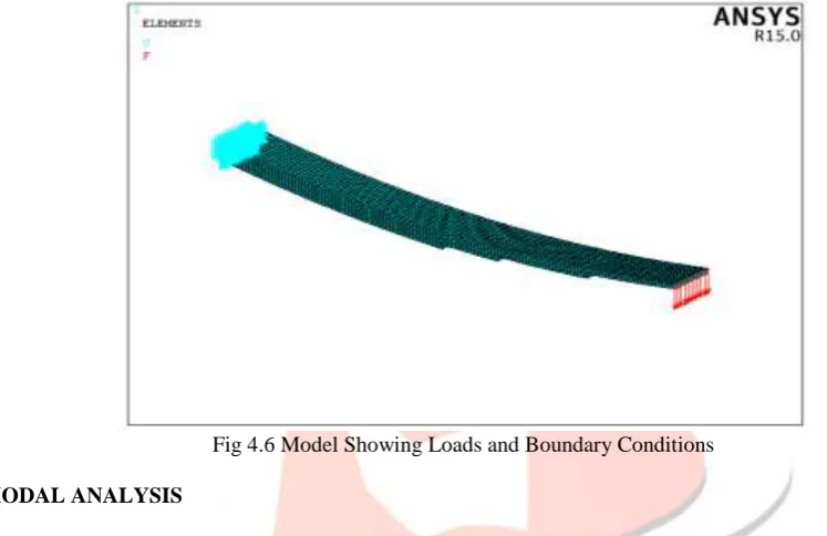
The following loads and boundary conditions are applied on the model. The model showing the loads and boundary conditions is shown in below figure.For Normal Static Load:
• All DOF’s are arrested at one end of the spring.
• Then, a force of 1190 N is applied on the other end in Y-direction.
For Full Bump Load:
• All DOF’s are arrested at one end of the spring.
• Then, a force of 2100 N is applied on the other end in Y-direction.
In case of Normal static load, a force of 1190 N is taken and for Full bump load a force of 2100 N is taken
Fig 4.6 Model Showing Loads and Boundary Conditions
b) MODAL ANALYSIS
Modal analysis is used to determine the natural frequencies and mode shapes of a component or structure. This analysis is a starting point for another analysis called the dynamic analysis, such as harmonic analysis, transient analysis, spectrum analysis etc. There are many uses of modal analysis. They are:
• Mode shapes and natural frequencies of the structure can be determined by using modal analysis.
• The mode shapes and natural frequencies are the most important constraints in designing a structure or component for dynamic load conditions.
• These are also required for doing the harmonic analysis or transient analysis or spectrum analysis.
Natural Frequency
The frequency at which the system tends to oscillate in the absence of any driving force is Called natural frequency. If any elastic body is considered, the free vibrations that are occurred in the body is called natural vibration and these vibrations occur at a frequency called natural frequency. Forced vibrations are different from natural vibrations. Forced vibrations occur at a frequency of applied force and is called the forced frequency. If the natural frequency and the forced frequency are equal, then the amplitude of vibration increases and this phenomenon we call it as “Resonance”.
Mode Shapes:
For every natural frequency there is a corresponding vibration mode shape. Most mode shapes can generally be described as being a bending mode, axial mode, torsional mode, or general modes. Like stress analysis models, probably the most challenging part of getting accurate finite element natural frequencies and mode shapes is to get the type and locations of the restraints correct. A crude mesh will give accurate frequency values, but not accurate stress values.
c) TRANSIENT ANALYSIS
IJEDR1804025
International Journal of Engineering Development and Research (
www.ijedr.org
)
142
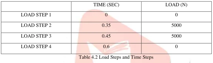
to any of static, harmonic and transient loads can be determined by using this analysis. The time scale of loading for this type of analysis is such that, where the damping and inertia effects are not considered to be important. Where the inertia and damping effects are not considered, we can use the static analysis in place of the transient analysis. Cases where these inertia and damping effects play a major role are under impulse loading conditions, i.e for example where there is a sharp or sudden load change in a fraction of time. Here, we will define our impulse load using load steps .The following graph and table shows the load steps and time steps which are taken for our present work. Uses of transient analysis are:Fig 4.72 Graph Showing Load Steps and Time Steps
TIME (SEC) LOAD (N)
LOAD STEP 1 0 0
LOAD STEP 2 0.35 5000
LOAD STEP 3 0.45 5000
LOAD STEP 4 0.6 0
Table 4.2 Load Steps and Time Steps
• The dynamic response of the structure or component under time varying loads can be determined using this analysis. • Here, the structure response at different times are calculated and a graph is obtained between the response quantity i.e
usually displacements versus time.
• “Peak” responses i.e maximum displacement and the relative time obtained on the graph is identified and the relative stresses and deflections with respect to that time are then determined.
V. RESULTS
a) COMPARISION OF STRESSES AND DEFLECTIONS IN STATIC ANALYSIS
The results of static analysis for all the materials are tabulated for comparison. The below table shows the comparison of results of static analysis for all the materials.
STATIC LOAD FULL BUMP LOAD
MAX. DEF STRESS MAX.DEF STRESS
STEEL 121.52 567.9 212.13 1010.67
E-GLASS/ EPOXY
124.064 164.147 218.936 289.672
S2-GLASS/ EPOXY
154.628 163.784 272.873 289.631
CARBON/ EPOXY
44.5895 167.569 78.6873 295.71
GRAPHITE/ EPOXY
25.076 164.809 44.2518 290.84
BORON/ ALUMINIUM
16.0702 162.558 28.3592 286.867
IJEDR1804025
International Journal of Engineering Development and Research (
www.ijedr.org
)
143
b) COMPARISION OF NATURAL FREQUENCIES IN MODAL ANALYSIS
The results of natural frequencies for all the materials are tabulated for comparison. The below table shows the comparison of results of natural frequencies for all the materials.
NATURAL FREQUENCIES
1 2 3 4 5
STEEL 20.03 90.03 228.41 430.82 710.82
E-GLASS/ EPOXY 37.0958 171.471 435.116 1001.21 1362.03
S2-GLASS/ EPOXY
26.7371 124.424 319.034 833.575 1241.25
CARBON/ EPOXY 62.0422 286.856 728.144 1601.16 2159.41
GRAPHITE/ EPOXY
78.6657 201.784 373.073 907.464 1205.38
BORON/ ALUMINIUM
82.4232 372.137 781.043 1639.44 2344.2
Table.2 Comparison of Natural Frequencies in Modal Analysis
c) COMPARISION OF STRESSES AND DEFLECTIONS IN TRANSIENT ANALYSIS
The results of deflections and stresses of transient analysis for all the materials are tabulated for comparison. The below table shows the comparison of results of stresses and deflections of transient analysis for all the materials.
AT TIME 0.35 SEC
DEFLECTION STRESS
STEEL 480.784 2410.06
E-GLASS/ EPOXY 526.091 696.547
S2-GLASS/ EPOXY 658.965 700.023
CARBON/ EPOXY 188.184 706.752
GRAPHITE/ EPOXY 107.498 693.683
BORON/ ALUMINIUM 67.9705 684.519
Table.4 Comparison of stresses and deflections in Transient analysis
VI. CONCLUSIONS
• Boron/aluminium and Graphite/epoxy are having lesser deflections with minimum allowable stresses when compared to steel and other composite materials in case of static analysis.
• Boron/aluminium and Carbon/epoxy are having higher natural frequencies which results in higher stiffness when compared to other composite materials and steel in case of modal analysis.
• Max amplitude is observed for steel, E-glass/epoxy, S2-glass/epoxy, Boron/aluminium at second mode whereas Graphite/epoxy has max amplitude at third mode.
• Boron/aluminium and Graphite/epoxy are having lesser deflections with minimum allowable stresses when compared to steel and other composite materials in case of Transient analysis.
• Boron/aluminium and Graphite/epoxy are best suitable materials for the leaf spring.
REFERENCES
[1]. Mahmood M. Shokrieh, Davood Rezaei , Analysis and optimization of a composite leaf spring,2003.
[2]. M.Raghavendra, Syed Altaf Hussain, V.pandurangadu, K.palani Kumar, Modelling and analysis of laminated
composite leaf spring under the static load conditions by using FEA,July-Aug 2012.
[3]. Sorathiya Mehul, Dhaval B.Shah,Vipul Bhojawala, Analysis of composite leaf spring using FEA for light vehicle mini
truck,Nov 2002.
[4]. Leaf springs, Mcgraw hill edition,pdf.
[5].Pankaj Sani ,Ashish Goel, Dushyant Kumar, Design and analysis of composite leaf spring for light vehicles,May 2013.
IJEDR1804025
International Journal of Engineering Development and Research (
www.ijedr.org
)
144
[7]. V.Pozhilarasu, T.Parameshwaran Pillai, Comparision of performance of glass fiber reinforced plastic leaf spring with steel leaf spring,Apr-Jun 2013[8].Malaga. Anil Kumar, T.N. Charyulu, Ch. Ramesh, Design optimization of leaf spring, Nov-Dec 2012.
[9].Ganesh.K, Gembiram, Elayaraja.R, Saravanan.R,Murali.K, Design and analysis of multi leaf springs using composite
materials,Apr 2014.
[10].Manjunath.H.N ,Manjunath.K, T.rangaswamy, Static analysis and fatigue life prediction of composite leaf spring for a
light commercial vehicle(TATA ACE),Jul 2014.
[11].Manjunath.H.N, Manjunath.K, T.Rangaswamy, Vibration Analysis of composite leaf spring for a light commercial vehicle (TATA ACE),Jul 2014.
[12].A.Venkata Vishnu, E.Sanjana, G.Guruvaiah, Optimization of heavy vehicle suspension system using composites,Sep
2013
[13].Ritesh Mistry, Dynamic analysis of a leaf spring,Apr-may,2014.
[14].Keshava Murthy Y.C,Chetan H.S,Dhanush C and Nithish Prabhu T, Design and finite element analysis of
hybrid composites mono leaf spring,Aug 2003.
[15].Wieslaw Krason, Jozef Wysocki,Analysis of vibrations of the simplified model of the suspension system with a double spring and a fluid damper,2011.
[16]. B.Vijaya Lakshmi,I.Satyanarayana,Static and dynamic analysis on composite leaf spring in heavy
vehicle,Oct-Dec 2012.
[17]. Sagar B Mahajan, M.C.Swami, Parmeshwar Patil,Experimental and FEA analysis of composite leaf spring by varying
thickness,Jan 2015.
[18]. Ashvini P.lad ,B.S.gandhare, A.S.Aradhye, N.V.Hargude,Deflection analysis of steel leaf spring vs
composite leaf spring through FEA software,Apr 2015.
[19]. T.N.V.Ashok Kumar, E.Venkateswara Rao, S.V.Gopal Krishna,Design and material optimization of heavy vehicle leaf