IJEDR1704222
International Journal of Engineering Development and Research (
www.ijedr.org
)
1392
FEM. Shackle Bracket is part of leaf spring assembly, which accommodates leaf deformation, when subjected to operational load. Simple, to allow for length changes of a leaf spring. A leaf spring suspension is a simple thing, above vehicle axle Leaf spring is assembled and supports the weight of the vehicle. As a leaf spring flexible to down or up, changes the length from eye to eye. Since one end is mounted fixed, and can’t move, at one end the changes of length happens, which has a shackle between the spring and frame to allow for movement. Provides support for front spring and Transfers forces to frame. In article structure of shackle bracket is used for study the structural behavior of main whole structure under different working load conditions. Casting & forming process is used for Shackle bracket. 3D modeling Pro-E software is used for of structure & Nastran software is used to carry out Linear & Non-linear Static analysis of structure to find out the deformation & maximum stresses.Keywords: Suspension Shackle Bracket, FEA
________________________________________________________________________________________________________
I. INTRODUCTION
Front Suspension is fitted with Semi elliptical leaf springs with shackle on rear side. This is a old suspension and for reducing inner leaf friction it should lubricated with graphite grease. Functions of suspension system are 1) Set Correct ride height of vehicle, 2) Support weight of vehicle, passenger and other load, 3) To safeguard against the road shocks, 4) To avoid the road shocks from transmitted to the vehicle components, 5) To preserve the stability of the vehicle in pitching or rolling, while in motion, 6) Wheel alignment correctly maintain, 7) Tire & road contact properly.
Figure 1.2: Flow of Study
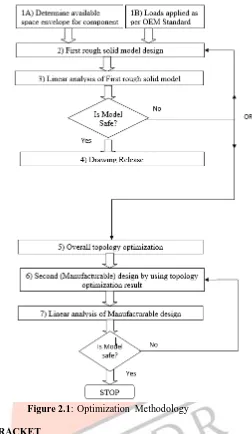
Next, conditions for optimization will be set. For improvement of characteristics will be set as objective function. And parameters which are considered to greatly contribute to the objective function will be determined as design variables. Optimization study using the simplified model will be conducted and the obtained result will be studied. Last, the advantage of the structure and validity of the study method will be verified vehicle model analysis on the structure identified
IJEDR1704222
International Journal of Engineering Development and Research (
www.ijedr.org
)
1393
Figure 2.1: Optimization Methodology
3. ANALYSIS OF SUSPENSION BRACKET
Prepare the G.A. drawing as per the dimension with technical data & calculate the all loads coming on structure. After final approve of GA prepare the part drawing. With the help of part drawing, prepare the 3D part modeling & then assemble. Convert the all 3D data in .step format for further work of analysis. In analysis work, create the mid-surface model, apply the boundary conditions like material & properties, constrains, apply the load, run the model for analysis. See the result & compare with standard specification. Create the final report & send for final modification.
Degree of Freedom: Any combination of the six nodal degrees of freedom (TX, TY, TZ, RX, RY and RZ) can be selected. In many cases however, standard combinations of degrees of freedom will be needed.
4. LINEAR ANALYSIS
The linear analysis of the model is carried out after the nonlinear analysis of the model, as the optimization is linear process. The advantages of the linear process over the non- linear process are as follows:1) It is a simple process, 2) It requires very less time for optimization process, 3)The required accuracy can be achieved.
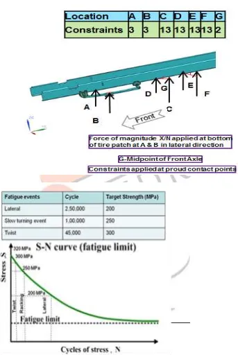
- Vertical load: Load act on vehicle when vehicle Come across a bump.
- Longitudinal load: Load act parallel to the vehicle. - Lateral load: Cornering force act while taking turn or force act in axial direction of wheel.
- Cross twist: Vehicle is twist rear cross wheel is in bump condition & when one front wheel is bump remaining wheel in rebound condition called cross twist
- Bogie twist: Vehicle is twist between cab and bogie called bogie twist. - Slow turning event: When a tractor with trailer is
IJEDR1704222
International Journal of Engineering Development and Research (
www.ijedr.org
)
1394
Figure 4.1: Boundary Conditions for Inertial Loadings
IJEDR1704222
International Journal of Engineering Development and Research (
www.ijedr.org
)
1395
Figure 4.3: Loads and Boundary Conditions –Bogie Twist
IJEDR1704222
International Journal of Engineering Development and Research (
www.ijedr.org
)
1396
[1] Caner Demird ogen. Jim Ridge, Paul Pollock andScott Anderson “Weight Optimized design of a front suspension component for commercial heavy truck” Technical report, SAE Documents2004-01- 2709.[2] Hui Wang, Zheng-Dong Ma, Noboru Kikuchi andChristophe Pierre “Numerical and experimental verification of optimum design obtained from topology optimization” Technical report, SAE Documents 2003-01- [3] 1333Hong Suk Chang “A Study on the Analysis method for Optimizing Mounting Brackets” Technical report, SAE Documents 2006-01-1480.
[4] Basem Alzahabi “Optimization of TransmissionMount Bracket” Technical report, SAE Documents 2003-01-1460. [5] G. Chaindussi, I Gaviglio, A. Ibba. “Topologyoptimization of an automotive component without final constraint specification” Technical report, Science Direct-July2003.
[6] Sung-Ling Twu, Robert L. Geisler “Structural Topology Optimization of Multilink SuspensionSystem Using ATOM” Technical
report, SIMULIA Community Conference-2012.
[7] Chang-Seong Ko, Dong-Ho Yoo, Kyung-WhanPark “Design of Steering Column Mounting Bracket for Vibration” Technical
report, SAE Documents 2003-01-2747.