New and Efficient ZCP-MPPT algorithm for SPV
systems
Sridharan B, C. Kanagasabapathi
Abstract: In recent times, environmental concerns are promoting the use of Solar energy to meet power requirements of both industrial and domestic setups. Practically SPV panels are used to convert the solar energy into electrical energy. The amount of power output from such panels depends on solar irradiation, ambient temperature and more importantly the electrical operating conditions. It is observed that the panels generate optimum power when its terminal voltage is maintained at certain point denoted by VMPPT. Accordingly, various Maximum Power point Tracking (MPPT) algorithms were developed with complexity and power efficiency trade-off to maximize the power transfer from SPV panels. Ongoing research works focus on improving the power efficiency, while reducing the circuit complexity of SPV systems. In this research paper, we propose a new Zero Crossing Point (ZCP) MPPT algorithm that has a potential to improve the efficiency of SPV systems while keeping the computational and hardware complexity to a minimum. We will also discuss practical implementation of this algorithm along with flow diagrams. Finally, we will present the experimental results that proves the functionality and advantages of the proposed algorithm. We are hopeful that this research work would be useful for those engaged in research as well as the industry engaged in building SPV based power systems.
Keywords:Incremental Voltage Product (IVP), Maximum Power Point Tracking, MPPT algorithms, Buck convertor, Solar power systems, SPV panels, Zero Crossing Point, ZCP-MPPT.
—————————— ——————————
1. INTRODUCTION
Traditionally fossil fuels like Gas, Coal are used for generation of Electricity, but as a side-effect it leads to water, air and land pollution. Hence focus is now more on production of clean and green energy. SPV based Electric power generation has acquired huge traction and is being promoted by government agencies though subsidies. As a use case, Solar based systems have greater advantages compared to diesel-based systems [2] for water pumping applications and it can be used as well for powering Wireless Sensor Network (WSN) nodes [3]. Naturally the industry and academia have taken-up research to improve the conversion efficiency of SPV panes and to extract maximum power from such panels. This in-turn results in less power wastage and need to install fewer panels to meet the given system power requirements. The output power from SPV panel depends on the irradiance level from Sun and ambient temperatures. While the variation for irradiance is shown in Fig. 1, the power decreases as the operating temperature of panel increases. Maximum Power point Tracking (MPPT) techniques are required to extract optimum power from Solar Panels under given environmental conditions. These algorithms ensure that the panels always operate close to VMPPT point so that
maximum available power PMAX is transferred to load
irrespective of actual load conditions.
_________________________________
Sridharan. B, PG Student of VLSI Design and Embedded System, VTU Extension Centre, UTL Technologies Ltd, Bangalore-22, India.
Email: [email protected]
C. Kanagasabapathi, Asst Professor, VTU Extension Centre, UTL Technologies Ltd, Bangalore-22, India. Email: [email protected]
Fig. 1. SPV panel characteristics: Power vs Irradiance level
Many MPPT algorithms and control schemes have been proposed in the past and are listed under section II of this report. The limitations of these algorithms are also listed for clear understanding and comparison.
This paper proposes new MPPT algorithm titled as Zero Crossing Point (ZCP-MPPT) that can maximize the power output from SPV panels while reducing the hardware complexity of the overall system. The practical implementation and observed results are also published for further analysis and design adaption by industry.
2. POPULAR MPPT ALGORITHMS AND THEIR
PERFORMANCE COMPARISON
are Constant Voltage Tracking, P&O, INC-CON, Variable Step Size (VSS). This reference report concludes that INC-CON method with variable step size has good performance in tracking MPPT point but makes the starting process more complex. But the CVT method shows the better performance in the starting process and is simple to implement. Simulation results that compares the various algorithms show that P&O and INC-CON algorithms have very similar performance and dynamic response and are superior to CVT methods. While the shortcoming of both methods is presence of steady state oscillations due to perturbations. Hence the modified VSS method that uses CVT method during start-up process show the best performance in response time and total power output.
Many Modern algorithms are also proposed and are characterised with its own merits and demerits. One such specific method is “A novel Fuzzy logic based adaptive proportional-integral-derivative (PID) control strategy for MPPT [4]”.
In summary, most popular MPPT algorithms being used in the industry are Perturb and Observe (P & O) and Incremental conductance (INC-CON). In majority of cases these are combined with other methods to speedup start-up and dynamic behaviour. The major disadvantages with these algorithms are listed below.
1. Current measurement is mandatory needing bulky sensor components.
2. Current amplifiers have nonlinear characteristics needing time consuming calibrations.
3. Power dissipation in resistance based current sensor circuit reduces power efficiency of the system by >1%.
We can now explore a new MPPT algorithm that can operate without needing any current measurement, hence mitigating the issues listed above.
3.
ZERO
CROSSING
POINT
-MPPT
(ZCP-MPPT)
METHOD
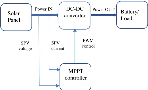
Typically, DC-DC buck converter along with MPPT algorithm is used in SPV power conversion systems to charge the battery during daytime. Most popular dynamic MPPT algorithms measure both SPV current and SPV voltage as parameters to locate MPPT point as outlined in Fig. 2, while the system level block diagram to implement Zero Crossing Point (ZCP-MPPT) method is shown in the Fig. 3. It is to be noted that proposed method measures only Load voltage to locate MPPT point.
Practically the voltage measurements are easy and accurate compared to Current measurements due to magnitudes involved. The need to have amplifiers to boost a typically low magnitude signals from current sensors increases circuit complexity, nonlinearity and standby power consumption.
Fig 2. Block diagram of typical dynamic MPPT system
Fig. 3. Block diagram of ZCP- MPPT system
SPV voltage can optionally be measured and used during power-on conditions to speed up the system response using Constant Voltage Tracking (CVT) algorithm and is not used further in the proposed algorithm.
3.1 Power and Voltage Waveforms at Load Port
Fig. 4 shows the standard power characteristics of the SPV panel and its corresponding output voltages at a specified load.
The output Voltage is given by the equation:
Vload = sqrt(η * Pinput * Rload)
Where η is the efficiency of the DC-DC converter.
Understandably the output voltage reaches the maximum when the input power corresponds to Maximum power point.
Solar Panel
DC-DC converter
Battery / Load
Power IN Power OUT
PWM
control LOAD
voltage
MPPT controller
Battery/ Load Solar
Panel
DC-DC converter
Power IN Power OUT
PWM control SPV
voltage
SPV current
Fig. 4. Relation between MPPT point and Output Voltage
3.2 Identification of MPPT from Output Voltage
The main objective of any MPPT algorithm is to identify the operating point that maximizes the power transfer from the SPV panel. ZCP-MPPT algorithm identifies such a point by introducing small, stepped, periodic but continuous changes in the input conditions. Such variations alter the output voltage that is delivered to the Load. The variation between two consecutive steps is labelled as ΔV. If the instantaneous output voltage is marked as Vout, Then
Incremental Voltage Product (IVP) = Vout * ΔV
It is to be noted IVP can be positive as well as negative quantity depending on the magnitude of ΔV.
Fig 5. Relation between IVP and Output Power
Fig. 5 shows the relation between IVP and Power output from SPV. As can be inferred, at MPPT point the IVP crosses the zero point. Hence the algorithm built using this principle is named as Zero Crossing Point (ZCP) algorithm.
4. ALGORITHM IMPLEMENTATION
Implementation of most popular P&O algorithm has been explained [6], similar approach is used in this paper. ZCP-MPPT algorithm is based on the principle that at ZCP-MPPT point IVP crosses the zero point. This chapter present the practical implementation of the proposed algorithm with relevant flow diagrams.
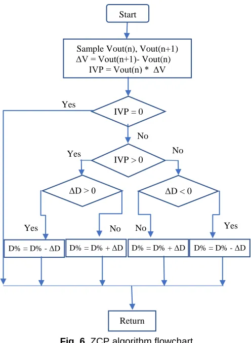
4.1 Flowchart for ZCP-MPPT Algorithm
ZCP-MPPT algorithm operates by periodically introducing small variations(ΔD) in PWM duty cycle (D%) of the DC-DC converter. When the duty cycle is increased, if the IVP point moves close to the Zero Crossing Point, then it is in the right direction, otherwise PWM duty cycle is deceased so as to move close to MPPT point.
Fig. 6. ZCP algorithm flowchart
The operating point of SPV panel is affected due to variations in PWM duty cycle. These variations reflect as small voltage variations in the output (ΔV). If the IVP product is either positive or negative we are away from MPPT point and hence effort is made to move close to that point.
The relation between variation in Duty cycle and magnitude of IVP is shown in the following figures.
Start
Sample Vout(n), Vout(n+1) ΔV = Vout(n+1)- Vout(n)
IVP = Vout(n) * ΔV
IVP = 0
IVP > 0
ΔD > 0
D% = D% - ΔD
Yes
Yes
No
No
Yes
Return
Yes
No No
ΔD < 0
Fig. 7. Zero crossing of IVP when Duty cycle increases
It is important to note that IVP transitions from positive to negative and meets “ZERO” point at MPPT region in both of the following scenarios:
When the duty cycle is reduced from 100% to 0%,
When the duty cycle is increased from 0% to 100%
Fig. 8. Zero crossing of IVP when Duty cycle decreases
After MPPT point is reached, further variation in PWM duty cycle is stopped till the IVP of subsequent sample varies appreciably. This standard method reduces the constant oscillations occurring around Maximum power point.
5 PRACTICAL IMPLEMENTATION
This algorithm is practically implemented and tested in solar based battery charger system. The block diagram of such a system is given below.
.
Fig. 9. Block diagram of Hardware for ZCP implementation
Solar charger system is essentially a DC-DC converter that works in buck mode and can be used to charge the battery and parallelly power the load as well. Microcontroller IC generates the PWM based switching signal, modifies it duty cycle dynamically depending on the output voltage measured and as per ZCP-MPPT algorithm. The Output voltage from battery is measured by simple voltage divider circuit and suitability conditioned by OP-AMP based amplifiers. Current measurements are not required by the algorithm and hence not implemented.
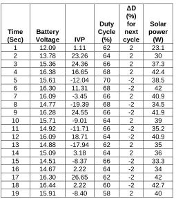
5.1 Test Results for ZCP-MPPT Algorithm
Testing is done with simulated SPV panel with 42WPeak and
the load is constituted by Battery and Resistive load generator. Output logs are collected, analysed and are tabulated as given below. Here ΔD is fixed at 2%.
Table. 1. Performance of ZCP-MPPT algorithm
Time (Sec)
Battery
Voltage IVP
Duty Cycle
(%)
ΔD (%) for next cycle
Solar power (W)
1 12.09 1.11 62 2 23.1 2 13.78 23.26 64 2 30 3 15.36 24.36 66 2 37.3 4 16.38 16.65 68 2 42.4 5 15.61 -12.04 70 -2 38.5 6 16.30 11.31 68 -2 42 7 16.09 -3.45 66 2 40.9 8 14.77 -19.39 68 -2 34.5 9 16.28 24.55 66 -2 41.9 10 15.71 -9.01 64 2 39 11 14.92 -11.71 66 -2 35.2 12 16.09 18.71 64 -2 40.9 13 14.88 -17.94 62 2 35 14 15.09 3.18 64 2 36 15 14.51 -8.37 66 -2 33.3 16 14.67 2.22 64 -2 34 17 16.30 26.65 62 -2 42 18 16.44 2.22 60 -2 42.7 19 15.91 -8.40 58 2 40
Solar Panel
Voltage Measurements PWM
signals
DC-DC Buck Converter
Microcontroller (DSPIC33EP64) with ZCP-MPPT algorithm
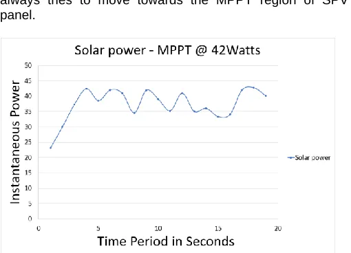
A graphical plot of the Power extracted from SPV panel over a specific time period of 20 Seconds is given in Fig.10. It reflects the satisfactory working of the algorithm as it always tries to move towards the MPPT region of SPV panel.
Fig. 10. Graphical plot of datapoints as per ZCP algorithm
6 CONCLUSION
Industry has accepted that MPPT algorithm is a de-facto standard to be implemented in SPV based power systems. MPPT ensures that the suitable operating conditions are maintained to enable the SPV panel to produce maximum power for the given irradiance level. Depending on the resources available on system, a trade-off is made in choosing the suitable MPPT algorithm between system complexity and power efficiency. Fractional VOC algorithm is
widely used in resource constrained platforms as it is simple to realise in hardware. On the other hand, P&O and INC-CON algorithms are proved to be efficient in dynamic environments. The major issues with these algorithms are the need to measure current, mathematical operators requiring DSP ICs etc., and hence leading to more complex system design. This research work has attempted to improve the efficiency of dynamic MPPT algorithms but keeps the hardware complexity at minimum level. New MPPT algorithm titled as ZCP-MMPT has been proposed and its functionality is also verified through practical implementation and observation. Major advantage of proposed algorithm is the reduced hardware complexity as no current measurements are needed and hence potentially leading to improved power conversion efficiency of SPV system.
REFERENCES
[1] Seok-II Go, Seon-Ju Ahn, Joon-Ho Choi, Won-Wook Jung, Sang-Yun Yun & IIKeun Song (2011) Simulation and Analysis of Existing MPPT Control Methods in a PV Generation System, Journal of International Council on Electrical Engineering, 1:4, 446-451, DOI: 10.5370/JICEE.2011.1.4.446
[2] Eric J. Schiller & Brian G. Latham (1988) Applying Photovoltaic Technology to Pump Water , Canadian Water Resources Journal / Revue anadienne des ressources hydriques, 13:1, 52-61, DOI: 10.4296/cwrj1301052
[3] Denis Dondi, , Alessandro Bertacchini, , Davide Brunelli, Luca Larcher, and Luca Benini: Modeling and Optimization of a Solar Energy Harvester System for Self-Powered Wireless Sensor Networks [4] Dnyaneshwar S. Karanjkar, S. Chatterji, Amod
Kumar & S.L. Shimi (2014) Fuzzy adaptive proportional-integral-derivative controller with dynamic set-point adjustmentfor maximum power point tracking in solar photovoltaic system, Systems Science & ControlEngineering, 2:1, 562-582, DOI: 10.1080/21642583.2014.956267
[5] Hiroo Konishi (2014) Study of MPPT Control Method for Large-scale Power Conditioning System in Hokuto Mega-solar System, Journal of International Council on Electrical Engineering, 4:2, 173-178, DOI: 10.5370/JICEE.2014.4.2.173
[6] Salman, Xin AI & Zhouyang WU, Design of a P & O algorithm based MPPT charge controller for a standalone 200W PV system, Protection and Control of Modern Power Systems, volume 3 Article Number: 25(2018).