ISSN (e): 2250-3021, ISSN (p): 2278-8719
Vol. 06, Issue 04 (April. 2016), ||V3|| PP 27-44
Combustion Characteristics of Inverse Diffusion Flames with Elliptic
Swirlers
A. Fahmy, H.A. Abotaleb, M.M. Kamal
Abstract:An experimental study was carried out to comparatively investigate the combustion performance of inverse diffusion flames with elliptic double swirlers and cross flow. A set of six double swirlers were used to study the effect of the swirl direction mode (co-versus counter-swirl), the primary and secondary swirl angles as well as the elliptic swirl aspect ratio on the combustion characteristics of LPG inverse diffusion flames. Under the same values of air and fuel flow rates, it was found that using the counter-swirl mode enhances the combustion performance in comparison to the co-swirl mode. This was indicated in terms of the flame length reduction by about 10% and the respective decrease by 19, 32 and 3% in the CO, UHC and NOx emissions. It was additionally found that the heat transfer from the flame to the combustor wall is enhanced by the counter-swirl mode. Increasing the secondary counter-swirl angle from 30° to 45°, while reducing the primary angle to 30°, results in decreasing the flame length by 7% and reducing the CO, UHC and NOx emissions respectively by 16, 12 and 11%. This indicates that intensifying the secondary swirl angle in the presence of a cross flow has a favorable impact on inverse diffusion flames. Using elliptic swirlers having aspect ratios of 1.25, 1.4 and 1.5 was proven to enhance the combustion characteristics. It was found that the use of elliptic swirlers leads to a shorter flame length, higher flame temperatures and reduced emissions in the case of the aspect ratio of 1.5. The swirler with the aspect ratio of 1.25 represented an optimum aspect ratio value, with a decrease of 30% in the flame length, and a reduction of the UHC and NOx emissions respectively by 61 and 24%; as compared to the circular swirler. On the other hand, the swirler with the aspect ratio of 1.4 achieved the lowest CO emissions with a decrease by 53% from the circular swirler base case. The swirler with the aspect ratio of 1.5 resulted in the highest flame temperature among the group of swirlers.
I.
NOMENCLATURE
CN : Counter Swirl Co : Co Swirl
CO : Carbon Monoxide IDF : Inverse Diffusion Flame NOx : Nitrous Oxides
UHC : Unburnt Hydrocarbons
II.
INTRODUCTION
Inverse diffusion flames (IDF) are types of flames, where the oxidizing air is introduced to the combustion chamber as the central jet, and surrounded by an outer fuel jet separately. Inverse diffusion flames are typically found in industrial applications in a confined (enclosed flame) arrangement, as well as unconfined (open flame) arrangements. Confined arrangements of IDF are less stable, due to the difficulty to obtain a balance between jet velocity, and burning velocity. The use of cross flow air in this case, is of great importance to stabilize the flame. Being non-premixed in their nature, IDFs combustion performance is highly dependent on the intensity of mixing between air and fuel streams. [1, 2, 3, 4]
Recently, IDFs has gained wide popularity and interest in combustion society, as they exhibit the favorable characteristics of both premixed flames and non-premixed normal diffusion flames. It is well known that premixed flames are more efficient, burn more intensely, but have narrow range of operation, due to flash back and lift – off phenomena. On the other hand, non-premixed normal diffusion flames are favored for their wide stability and range of operation, but they are well known for their high soot loading characteristics; which limit their use as the demand for cleaner and less polluting flames is increasing. In this regard, IDF is well positioned between these two types of flames, combining the advantages of both premixed, and non-premixed diffusion flames. Many researches has showed the advantages of IDFs with respect to decreased exhaust gases emissions, shorter flame lengths that leads to compact combustors designs and enhanced combustion efficiency and performance. [1, 2, 3, 4]
Amin [6] studied the use of vane, double counter swirlers, and reported the enhancement of flame stability, reduced emissions and improved combustion performance of swirled flames. H. S. Zhen et.al. [2, 3], studied the effect of swirl, on thermal, emissions and heat transfer characteristics of IDFs. They reported that the swirled IDF has main recirculation zone closer to the burner exit, resulting in a more stable, and shorter flame length; lower NOx and CO emissions were achieved by the swirled IDF.
Another means of interest in the enhancement of combustion performance, is the use of non-circular jets. Extensive studies of the effect of non-circular jets, as a passive means of flow control in the combustion processes, have been conducted for the last couple of decades. Non-circular jets have been reported and proven to be a low cost, efficient way of enhancing combustion characteristics, as the only change employed in these techniques is the change of nozzles geometry [7, 8]. Elliptical jets in particular, has gained a lot of interest during the last four decades, since the flow turbulence and features induced by their asymmetric nature is of favorable effect [9]. Hakem et.al. [10], proved that elliptic jet with varying large aspect ratio can produce much higher dilution than circular nozzles. Paschereit and Gutmark [11] studied a swirled stabilized burner of elliptic shape at different conditions. They reported that the elliptical profile achieved better mixing of fuel and air, lower NOx emissions by four times, lower CO emissions by a factor of 2 or 3 and lower UHC emissions. Kashkousha et.al. [12, 13] studied IDFs with elliptical swirling jets and cross flow. They reported that varying the relative angle, aspect ratio of elliptic jets and cross flow; a significant enhancement of combustion performance could be obtained. Increasing the aspect ratio of the jets from 1.5 to 3.3, resulted in an increase of 9% in the combustion efficiency, a decrease in CO emissions to a minimum value of 12.3 g/kg and a decrease of the UHC in the level of 25%.
On the light of the above mentioned features, the present study was motivated towards the combination of the elliptical jets and double swirling of the fuel jet, in order to enhance the combustion characteristics of confined IDFs, with cross flow. This is achieved by using double vane swirlers, of elliptic profile with different aspect ratios.
III.
EXPERIMENTAL SETUP
4.1.Test rig:
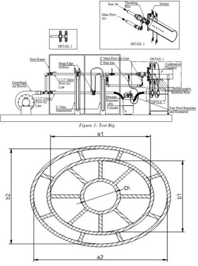
Figure 1 shows the details of the test rig used in the present study. As shown in the figure, the test rig consists of an air blower, main flow air line, cross flow air line, fuel line and the combustion chamber. Combustion air is supplied via an air blower, which is connected to a 1.5 hp, single phase electric motor. Air is then delivered to the combustion chamber via 1.5" main flow line, and 1.5" cross flow line. Main flow air line is reduced at the entry to the combustion chamber, to a size of 7 [mm] internal diameter, in order to increase the main air flow velocity, and enhances the entrainment of air and fuel streams. The main air flow is introduced to the combustion chamber in coaxial direction, at the center of the reacting jets and un-swirled. On the other hand, cross flow air is introduced to the combustion chamber in two stages, by means of four pipes per stage, each pipe is of 0.25" size, and distributed radially around the combustion chamber, spaced 90° on the circumference of the combustion chamber. The flow rate of air through the main air, and cross flow air lines, is controlled by means of 1.5" ball valves. Furthermore, the flow rate of cross flow air, issuing into the combustion chamber by the 0.25" pipes on the circumference of the combustion chamber walls, is controlled by 0.25" valves; in order to balance the amount of cross flow air issuing from each pipe.
Fuel used in the present study is commercial Liquefied Petroleum Gas (LPG), which is stored in a gas cylinder. A flow regulating device, with built in pressure regulator is used to control the flow rate of fuel from the LPG cylinder, and the pressure regulator ensures a constant pressure, steady flow of fuel. The fuel is injected coaxially, surrounding the main flow air (typical arrangement of inverse diffusion flames), and is swirled by the primary and secondary swirler vanes. Fuel is forced through a narrow passage formed by a coaxial throttling disc mounted just before the swirler, in order to increase the fuel jet momentum, before being swirled by swirler vanes, to enhance the mixing and entrainment characteristics of the fuel jet.
The combustion chamber is a steel pipe, of 70 [cm] length, 25 [cm] internal diameter, and a thickness of 1 [cm]. The chamber is equipped with cross flow lines as described before, and six ports for radial temperature measurements, distributed axially along the combustion chamber. The axial distances of these ports are detailed in the results sections, discussed later.
Six swirlers were fabricated, for the purpose of the current study. Five of the swirlers are of elliptic profile and one base swirler of normal circular profile. Figure 2 and table 1 show the main layout of the swirlers and the basic dimensions of each swirler, respectively. Each swirler consists of a central circular ring, for main air flow; and two elliptic rings equipped with straight vanes, that introduce the swirling action to fuel stream.
4.2.Measuring instruments:
[mm]. The two orifice meters were calibrated and the coefficient of discharge of each one is determined before using them in the measurements. Fuel flow rate is measured by a calibrated Rota meter.
A Platinum – Platinum Rhodium 10% (Pt –Pt Rh 10%) [S-type] thermocouple, of 1 mm bead diameter, and 35 [cm] long was used for flame temperature measurements. A digital reader was used in conjunction with the thermocouple for the temperature readings. The thermocouple and the digital reader were calibrated, and a heat balance analysis is conducted for temperature correction due to radiation errors.
A calibrated gas analyzer with digital display, model Lancom III, was used to measure the emissions of unburnt hydrocarbons (UHC), carbon monoxide (CO), and nitrous oxides (NOx). These emissions were measured at the exit plane of the combustion chamber.
Figure 1: Test Rig
IV.
RESULTS AND DISCUSSIONS
All the swirlers in this investigation, were tested under the same conditions of main air flow rate of 57 [l/m], cross flow air of 279 [l/m], fuel flow rate of 10.45 [l/m]. The actual air to fuel ratio correspondingly is 16.97, and the equivalence ratio Φ is 0.91 indicating a lean invers diffusion flame. The following are the experimental results and discussion.
5.1.The effect of swirl direction mode (co versus counter swirl):
In this case, two swirlers are compared. Both of the two swirlers has the same aspect ratios of 1.4, the same primary (inner) swirl angle of 30° and the same secondary (outer) swirl angle of 45°. The only varying parameter is the relative relation between primary and secondary swirl angles, in which one of them is Co swirl (angles in the same direction) and the other is Counter swirl (angles in different directions).
5.1.1. Visual flame structure:
Figure 3 shows the flame images produced in each of the two cases (Co and counter swirls). It is obvious that counter swirl produces blue flame, unlike the Co swirl which produces a remarkably less bluish flame. This indicates better mixing of air and fuel in the case of counter swirl which resulted in lower percentage of UHC. This conclusion is verified by the gas analysis of UHC which indicates lower readings in the case of counter swirl, as discussed in the gas analysis section.
This is also in a good agreement with M.D. Durbin and D. R. Ballal [14], who reported in their investigation in a step swirl combustor, that Co swirl flame show some yellowish streaks downstream, which is an indication of non-uniform mixing; while the counter swirl flame revealed bluish flame. This is an evidence of the enhanced mixing by counter swirling mode.
(b)
Figure 3: Flame image produced by (a) 30-45-CN-1.4 swirler, and (b) 30-45-Co-1.4 swirler
5.1.2. Temperature distribution:
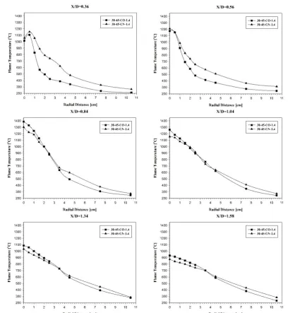
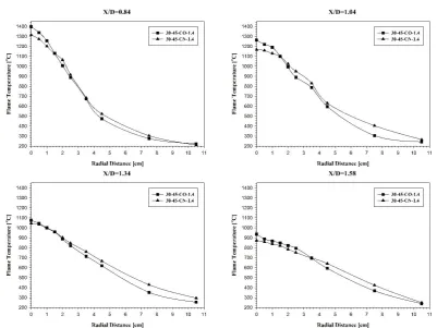
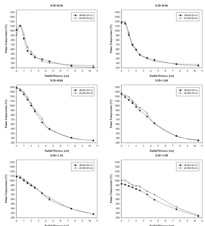
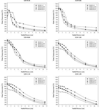
Figures 4 and 5 show the radial temperature distribution, at different axial positions along the combustor for Co and counter swirlers, along the major and minor axis respectively.
The temperature distributions reveal that up till axial distance of X/D=0.56, the counter swirler has higher temperature distribution than that of the Co swirler. This indicates higher turbulence mixing and shear rates in the case of counter swirler flame. As we proceed with the temperature measurements, we can see that the rapid rate of heat transfer from the counter swirler in the first region causes the counter swirler flame distribution to flatten more rapidly than that of the Co swirler flame, in this case we start to observe that the temperature readings of the Co swirler flame becomes higher than the counter swirler flame, as the Co swirler flame is still developing due to the lower rates of mixing and turbulence.
It is also noticed that for both of the two swirlers' flames, the temperature distribution along the major axis and the minor axis are nearly the same. This indicates that the swirl effect combined with the cross flow effect in these swirlers dominated the effect of elliptic profile and the shifting axis theorem, and imposed a uniform temperature field along major and minor axes of both of the swirlers. This observation agrees well with that made in the work of OA Kashkousha et.al. [12]; in which it is reported that swirling seems to destroy the benefits of elliptical jets represented in the axis switch phenomena, which is manifested in the similarity of the temperature distribution along major and minor axes. However, the addition of elliptic profile stretches the circular paths set by double swirling of the flow, and hence improving the flow straining effects.
The average wall temperature in the case of counter swirl (175 °C) is higher than that of the Co swirl flame (154 °C), which indicates better heat transfer to walls in the case of counter swirler.
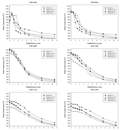
Figure 5: Radial temperature distribution for 30-45-Co-1.4 swirler versus 30-45-CN-1.4 swirler, along minor axis, at different axial positions X/D
5.1.3. Exhaust gases analysis:
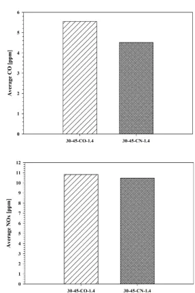
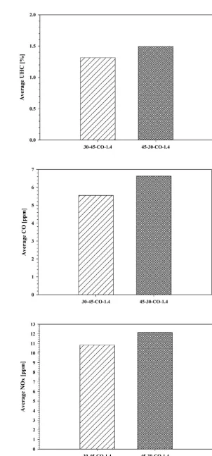
Figures 6 shows the average UHC, CO and NOx emissions respectively; for Co and counter swirlers. As indicated in the figures, the UHC emission in the case of counter swirl flame is reduced in the level of 32%, indicating better mixing and shear rates and combustion efficiency of counter swirler flame. These measurements are verified by the more bluish flame produced by the counter swirler, that was demonstrated previously.
The CO emissions in the case of counter swirl flame is reduced by a 19% compared to the Co swirl flame, indicating lower dissociation rates and improved mixing and turbulence in the case of counter swirler flame. NOx emissions are lower in the case of counter swirl flame, by a decrease of 3%. This is due to the higher temperature levels in the Co swirl flame, in most of the flame regions.
(b)
(c)
Figure 6: Average emissions comparison for 30-45-Co-1.4 swirler versus 30-45-CN-1.4 swirler, (a) Average UHC emissions, (b) average CO emissions and (c) average NOx emissions.
5.1.4. Flame length:
The counter swirler flame is shorter than the Co swirler flame (counter swirler flame length is 30 [cm], while that of the co swirler is 33.5 [cm]), indicating better mixing in the case of counter swirl mode. This result is in good agreement with the temperature profiles shown previously.
5.2.The effect of primary and secondary swirl angles:
In this case, two swirlers are compared to investigate the influence of primary and secondary swirl angles. Both of the two swirlers have the same aspect ratio of 1.4, the same relative relation between the primary and secondary swirlers (both of the two swirlers are Co swirl type). The only varying parameter is the primary and secondary swirl angles, in which one of them has a primary swirl angle of 30° and a secondary swirl angle of 45° (will be referred to as 30-45 in the discussion); and the other one has a primary swirl angle of 45° and a secondary swirl angle of 30° (will be referred to as 45-30 in the discussion).
5.2.1. Visual flame structure:
(a)
(b)
Figure 7: Flame image produced by (a) 45-30-Co-1.4 swirler, and (b) 30-45-Co-1.4 swirler
5.2.2. Temperature distribution:
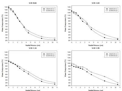
Figures 8 and 9 show the radial temperature distribution, at different axial positions along the combustor for 30-45 and 45-30 swirlers, along the major and minor axis respectively.
The temperature distributions reveal that up till axial distance of X/D=1.34, the two swirlers have approximately the same temperature values and quite the same distribution pattern. However the 45-30 swirler indicated higher temperature values at axial distances beyond axial distance of X/D=1.34, which is a result of poor mixing in 45-30 swirler compared to 45-30-45 one; and hence producing longer flame length. This is verified by the measurement of flame length, which indicated that 45-30 has longer flame than 30-45 swirler as discussed later. Maximum flame temperature is nearly the same in the two swirlers with no significant change (1398°C for 30-45 swirler and 1382°C for 30-45-30). The average wall temperature is slightly higher in the case of 30-45-30 swirler (171°C in case of 45-30 swirler and 154°C in the case of 30-45 swirler), mostly because of the longer flame length in the case of 45-30 swirler.
Figure 9: Radial temperature distribution for 30-45-Co-1.4 swirler versus 45-30-Co-1.4 swirler, along minor axis, at different axial positions X/D
5.2.3. Exhaust gases analysis:
Figures 10 shows the average UHC, CO and NOx emissions respectively; for 30-45 and 45-30 swirlers. As indicated in the figures, the UHC emissions in the case of 30-45 swirler flame is lower than that of the 45-30 swirler flame in the level of 12%, indicating better mixing and shear rates and combustion efficiency of 30-45 swirler flame. These measurements are verified by the more bluish flame produced by the 30-45 swirler, as discussed before.
The CO emissions in the case of 30-45 swirler flame is lower than that of the 45-30 swirler flame in the level of 16%, indicating higher dissociation rates and deteriorated mixing and turbulence in the case of 45-30 swirler flame.
NOx emissions are higher in the case of 45-30 swirl flame. This is due to the higher temperature region in 45-30 swirler due to the longer flame length as indicated above.
(a)
(b)
(c)
5.2.4. Flame length:
The 30-45 swirler flame was shorter than the 45-30 swirler flame (45-30 swirler flame length is 36 [cm], while that of the 30-45 swirler is 33.5 [cm]), indicating better mixing in the case of 30-45 swirler. This agrees well with M.D. Durbin and D. R. Ballal [14], who reported that when outer swirl intensity is high, by means of increasing the outer swirl angle and/or the outer jet velocity, the flame length decreases.
5.3.The effect of aspect ratio:
In this case, four swirlers are to be compared, to investigate the effect of varying the aspect ratio of elliptic swirlers on the combustion performance. One of the swirlers is circular (aspect ratio = 1), and the rest are elliptic with aspect ratios of 1.25, 1.4 and 1.5. All of the four swirlers have the same primary swirl angle of 30° and the same secondary swirl angle of 45°, and all of them are of Co swirl type. The only varying parameter is the aspect ratio of the elliptic swirlers. It should be noticed that the aspect ratio for each individual swirler is the same for the primary swirler as well as in the secondary swirler.
5.3.1. Visual flame structure:
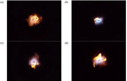
Figure 11 shows the flame images produced by each of the investigated swirlers. As seen from the photos, it is obvious that circular swirler produced the most yellowish flame. For the elliptic swirlers, the swirler with aspect ratio of 1.25 resulted in the most bluish flame, and increasing the aspect ratio furthermore to 1.4 and 1.5, resulted in a flame that is less bluish. This indicates that in general, the elliptic profile of the swirlers enhanced the mixing rate of fuel and air streams more than that obtained by regular circular swirlers. The enhanced mixing resulted in lower percentages of the UHC as well verified by the UHC emissions measurements that will be discussed later. However increasing the aspect ratio to increase turbulence and hence mixing rate doesn't seem to enhance the combustion performance further more. As we can see, increasing the aspect ratio to 1.4 and then to 1.5 resulted in a continuous increase in the UHC percentage and the flame became less bluish and more yellowish in the 1.5 aspect ratio swirler. The UHC measurements are in a very good agreement with the flame appearance and the conclusion stated.
(a) (b)
(c) (d)
Figure 11: Flame images produced by (a) circular swirler, (b) swirler of aspect ratio 1.25, (c) swirler of aspect ratio 1.4 and (d) swirler of aspect ratio 1.5
5.3.2. Temperature distribution:
and the distribution of the temperature gets flattened earlier than the other swirlers. The 1.4 aspect ratio swirler follows the 1.25 aspect ratio swirler and then the 1.5 aspect ratio. Finally the circular swirler develops slowly and the temperature profile tends to flatten in a slower rate. As a result to this observation, the flame length of the circular swirler is the largest. The 1.25 aspect ratio swirler in this manner achieves the minimum flame length, followed by the 1.4 aspect ratio swirler and then the 1.5 aspect ratio swirler, as indicated in the flame length measurement discussed later.
The increased turbulence caused by the 1.5 aspect ratio swirler resulted in the maximum flame temperature compared to the other swirlers, as the mixing and shear rates are faster than the rate of combustion, causing a delay in the development of flame and hence a lower conduction rate across the flame which allows the flame to reach higher temperature levels. The 1.25 aspect ratio swirler achieved the lowest maximum flame temperature among all the swirlers, as the mixing rate is in an optimum value with the combustion rate, which enhances the combustion process and the conduction heat transfer across the flame, causing a drop in the maximum flame temperature.
Again it is noticed here that the temperature distribution along the major and minor axes is similar in the case of 1.25 and 1.4 aspect ratios swirlers. However, the 1.5 aspect ratio swirler deviated from this behavior. Due to the increased aspect ratio of 1.5, the shifting axis theorem effect tends to dominate the swirling and cross flow effects, causing the temperature distribution to be asymmetric, unlike the other swirlers in this work.
Figure 13: Radial temperature distribution for circular swirler, 1.25 aspect ratio swirler, 1.4 aspect ratio swirler and 1.5 aspect ratio swirler along minor axis, at different axial positions X/D
5.3.3. Exhaust gases analysis:
Figures 14 shows the average UHC, CO and NOx emissions respectively; for the circular, 1.25, 1.4 and 1.5 aspect ratio swirlers.
The UHC emissions are the lowest in the case of 1.25 aspect ratio swirler, followed by the 1.4 aspect ratio swirler, then the 1.5 aspect ratio swirler and finally the circular swirler; which achieved the highest rate of UHC emissions. These measurements are in good agreement with the visual flame structure and appearance discussed earlier.
The CO emissions in the case of circular swirler is the highest, due to relatively bad mixing and elevated flame temperature that motivates dissociation reactions. The 1.25 aspect ratio swirler comes in the second place after the circular swirler, although the 1.25 swirler achieves the best mixing rates. This is mostly because of the low flame temperature encountered with the 1.25 swirler, in which the oxidation reaction of CO to CO2 is slower than that in the higher temperature rates [16]. This results in increasing the CO emission in the 1.25 swirler. The 1.4 swirler achieves the lowest CO emission levels, representing an optimization between mixing rates, flame temperature and dissociation rate.
1425°C, then 1.4 with maximum flame temperature of 1398°C and finally the lowest flame temperature of the 1.25 swirler of 1287°C.
(a)
(b)
(c)
5.3.4. Flame length:
The 1.25 aspect ratio swirler acquired the shortest flame of 26 [cm] length, followed by the 1.4 aspect ratio swirler with a flame length of 33.5 [cm], then the 1.5 aspect ratio swirler with 34.5 [cm] and finally the circular swirler with the longest flame of 37 [cm] length.
The previous discussion proves that using elliptic swirlers in general, enhances the combustion performance more than encountered with circular swirlers. This fact is in good agreement with the work of OA Kashkousha et.al. [12], in which it is reported that recirculation zone is more enlarged in the case of elliptical swirled IDF, as the swirling flow path is elongated for the tangential velocity to decay faster; and consequently the adverse pressure gradient increase. This eventually leads to an enhancement in the combustion process stability.
V.
CONCLUSIONS
As discussed in the previous sections, the following can be concluded:
Using counter swirl mode leads to shorter flame length, lower UHC, CO and NOx emissions, and better heat transfer rates to the walls of the combustor. This indicates that counter swirl in the case of IDFs has better combustion performance than Co swirl. The fact that counter swirling results in better combustion characteristics than Co swirling, is justified as at low levels of mixing encountered in IDFs, with large area of the fuel stream, Co swirl doesn’t reach the maximum level of mixing after which the flame quenching occurs. Instead, there is still a continuous enhancement by counter swirl. In other words, counter swirl in IDFs doesn’t cause over turbulence rates, as the nature of IDFs requires higher rates of turbulence than that encountered in normal diffusion flames.
Increasing the secondary swirl angle results in shorter flame length, lower UHC, CO and NOx emissions. This indicates that the secondary swirl angle in the case of IDFs has more influence on enhancing combustion performance than the primary swirl angle. In other words, the effect of intensifying the swirl action in the secondary swirler is more important and has improved combustion characteristics in IDFs. This effect arises due to the nature of combustion in confined IDFs, where cross flow air has a dominating effect on combustion process. In our case the cross flow air represents about 80% of the total air stream, so it is more important to enhance the swirl intensity near the cross flow region, which means the secondary swirl stream. That’s why the 30-45 swirler revealed better combustion performance.
The use of swirlers of elliptic profile leads to a significant enhancement on the combustion performance of inverse diffusion flames. The 1.25 aspect ratio swirler represents an optimum value among the group of elliptic swirlers in this study. The 1.25 swirler achieved the best mixing rates, the least UHC emissions, the shortest flame length and the lowest NOx emissions. Further increase in aspect ratios deteriorates the combustion performance, however, the performance of elliptical swirlers in general is proven to enhance the combustion characteristics of IDFs.
It is noticed in the elliptic swirlers that the temperature distribution along the major axis and the minor axis are nearly the same. This indicates that the swirl effect combined with the cross flow stream in these cases dominates the effect of elliptic profile and the shifting axis theorem effect, and imposed a uniform temperature field. The only swirler that deviated from this behavior is the 30-45-Co-1.5. The high aspect ratio of 1.5 in this particular swirler caused the temperature distribution to vary from major to minor axis, which indicates a change in the behavior such that the shifting axis theorem effect dominated the effect of swirl and cross flow.
Based on the above analysis, the best swirler among this study is the 30-45 Counter swirler, with aspect ratio 1.4. This swirler has optimum values for exhaust gas emissions with significantly low rates of CO and UHC and hence the highest combustion efficiency, a moderate flame temperature with high heat transfer rate to the walls. The counter swirler flame is the second shorter flame just after 1.25 aspect ratio swirler.
REFERENCES
[1] Zhen Hai Sheng, "Thermal and Emission Characteristics of an Inverse Diffusion Flame With Induced Swirl", Ph.D. Thesis, The Hong Kong Polytechnic University, China, September 2009.
[2] H.S. Zhen, C.W. Leung, C.S. Cheung, "Thermal and emission characteristics of a turbulent swirling inverse diffusion flame", International Journal of Heat and Mass Transfer, 2009.
[3] H.S. Zhen, C.S. Cheung, C.W. Leung, H.B. Li, "Thermal and heat transfer behaviors of an inverse diffusion flame with induced swirl", Fuel Journal, 2012.
[4] Andrzej Sobiesiak, Jamie C. Wenzell, "Characteristics and Structure of Inverse Flames of Natural Gas", Proceedings of the Combustion Institute, 2005.
[5] A.K. Gupta, D.G. Lilley, N. Syred, "Swirl Flows", Abacus Press, 1984.
[6] E.M. Amin, "Influence of Counter Rotating Swirl on Combustion and Emissions", Ph.D. Thesis, University of Leeds, England, September 1991.
[8] S.R. Gollahalli, "Jet Flames from Noncircular Burners", Sadhana Journal, vol.22, part 3, June 1997. [9] O.A. Kashkousha, "Investigation of Combustion Utilizing Non-Circular Ports", M. SC. Thesis, Ain
Shams University, Egypt, 2012.
[10] M. Hakem, A. Hazzab, A. Ghenaim, "Experimental Investigation of Elliptical Jet in Coflow", International Journal of Applied Engineering Research, January 2007.
[11] C.O. Paschereit, E.J. Gutmark, "Enhanced Stability and Reduced Emissions in an Elliptic Swirl-Stabilized Burner", AIAA Journal, Vol.46, No.5, May 2008.
[12] O.A. Kashkousha, M.M. Kamal, A.M. Abdulaziz, M.A. Nosier, "Inverse Diffusion and Partially Premixed Flames with Elliptical/Swirling- and Cross-Flows", Proceedings of the Institution of Mechanical Engineers, Part A: Journal of Power and Energy [PIA], 2014.
[13] O.A. Kashkousha, M.M. Kamal, A.M. Abdulaziz, M.A. Nosier, "Concentric Elliptical Jet Diffusion Flames with Co- and Cross-Flows", Experimental Thermal and Fluid Science, 2012.
[14] M.D. Durbin, D.R. Ballal, "Studies of Lean Blowout in a Step Swirl Combustor", ASME Journal, Vol.118, January 1996.
[15] Bach T. Vu, F.C. Gouldin, "Flow Measurements in a Model Swirl Combustor", AIAA Journal, Vol.20, No.5, May 1982.