(www.dvpublication.com) Volume 3, Issue 1, 2018
DESIGN AND ANALYSIS OF A TAPERED COMPOSITE
LEAF SPRING
K. Diwakar*, N. Bhaskar**, A. Surendra***, Y. Uday Kumar****
& C. Srikar Rao*****
Assistant Professor, Department of Mechanical, Annamacharya Institute of Technology & Science, Kadapa, Andhra Pradesh
Cite This Article: K. Diwakar, N. Bhaskar, A. Surendra, Y. Uday Kumar & C. Srikar Rao, “Design and Analysis of a Tapered Composite Leaf Spring”,International Journal of Advanced Trends in Engineering and Technology, Volume 3, Issue 1, Page Number 20-30, 2018.
Abstract:
The rear suspension system of a “Mahindra Commander 650 di” is chosen for the present study. The vehicle rear suspension system has ten number of leafs which is made up of steel and laminated with each other. CATIA P3 V5 R19 is used for the modelling of the suspension system. The designed model is analyzed by using ANSYS Workbench 14.5 software. The stress and deflection results from Finite Element Method (FEM) are compared with the analytical solution. The optimized tapered leaf spring is analyzed using ANSYS workbench. The main objective of this study is to reduction of the bending stress and weight of the leaf spring. In this study, composite material is used and flat plates are replaced with tapered plates with uniform rectangular cross-section. The thickness varies from eye end to centre and width is same along the spring length. The thickness is more at the centre and reduces towards to eye end. As per the numerical analysis, the optimized tapered leaf spring showed better results in bending stress and weight than the conventional leaf spring.
Key Words: ANSYS, CATIA P3 V5 R19, FEM, Stress & Rear Suspension 1. Introduction:
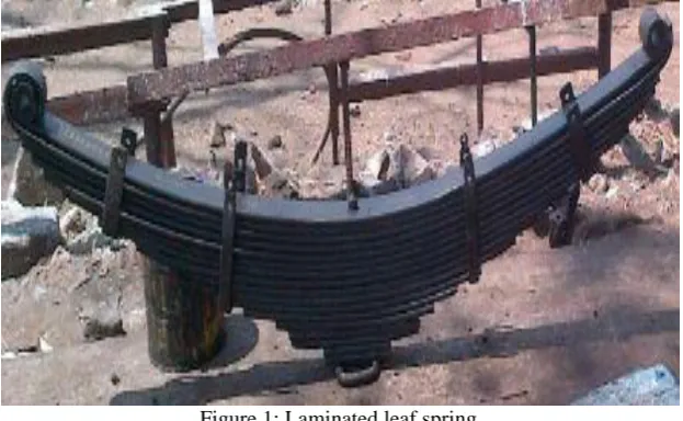
Usually leaf springs are displayed as a package of prismatic bars with progressively reducing lengths with uniform thickness and width. Leaf spring is a humble form of spring, generally used for the suspension system in automobiles like jeep, buses and heavy loaded commercial vehicles, etc.
Figure 1: Laminated leaf spring
Generally the springs are designed to absorb and store energy when load is applied after the load is removal it will regain its original position by releasing the stored energy. So it’s clear that to design a leaf spring the strain energy is the main factor. The specific strain energy can be expressed as Eq. (1).
𝑈 =1
2 𝜎2
ρ𝐸 (1)
Where σ is the ultimate stress, E is the young’s modulus; ρ is the density of the spring material
The materials having low density and low young’s modulus with high strength are preferable to make a leaf spring. The composite materials are especially having these properties, so that from past few years the leaf spring manufacturing industry’s put effort to make the leaf spring by using the composites.
(www.dvpublication.com) Volume 3, Issue 1, 2018 1.2 Characteristics of Leaf Spring:
Supports the weight of the chassis
Controls chassis roll more efficiently
Controls rear end wrap-up
Controls axle damping
Controls braking forces
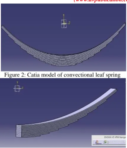
Controls wheelbase lengths under acceleration and braking condition 2. Modelling of Leaf Spring:2.1 Design and Analysis of Convectional Leaf Spring: The 3D model of the” Mahindra Commander 650 di” Convectional leaf spring is designed by using CATIA V5 R19. This release of CATIA, extends the power of leading edge engineering practices to include relation design, which results in
Higher quality design
More opportunities for innovation
Fewer engineering changes later in the design cycle
2.2 Length Calculation of Leaves: In this study the leaf spring consists of 10 leafs out of which two are master leafs and remaining are graduated leafs. The effective length of the master leaf is 1020mm and in-effective length or band length is 100mm.
Length of 10th leaf =𝐸𝑓𝑓𝑒𝑐𝑡𝑖𝑣𝑒 𝑙𝑒𝑛𝑔𝑡
𝑛 −1 + 𝐼𝑛𝑒𝑓𝑓𝑒𝑐𝑡𝑖𝑣𝑒 𝑙𝑒𝑛𝑔𝑡
Where n is number of leafs
= 1020
10−1× 1 + 100 = 213.333mm
Length of 9th leaf = 1020
10−1× 2 + 100 = 326.667mm
In the similar way we have to calculate the length of the remaining leaves as shown in below table. Here we consider the number of full length leafs are 2, so that the length of the 1st leaf is equal to the length of second leaf that is 1020mm. The below table shows the full length and half length of the leaves with respective to the leaf serial number.
Leaf number
Full length of the leaves, mm
Half length of the leaves, mm
1 1120 560
2 1120 560
3 1007 503.5
4 894 447
5 780 390
6 667 333.5
7 554 277
8 440 220
9 327 163.5
10 214 107
Table 2: Length of the leaf spring 2.3 Mass Calculation of the Conventional Leaf Spring:
To calculate the mass of leaf spring, mainly two parameters are known that is first one is density of the material and second one is volume of the model. Usually the density of the material is known and based on the given specifications of the model the volume is easily calculated.
𝐷𝑒𝑛𝑠𝑖𝑡𝑦 𝜌 = 𝑀𝑎𝑠𝑠
𝑉𝑜𝑙𝑢𝑚𝑒 [1]
Density of the “65Si7”= 7860 kg/m3 Width of the leaf spring = 50mm Thickness of the leaf spring = 6 mm
Volume of the 1st leaf(V1) =area×length of the1st leaf = 50 × 6 × 1120 = 336,000 mm3
In the similar way we calculate the volume of remaining leafs and also calculate the total volume of the convectional leaf spring by using the following formulae.
Total volume of the 10 leaves (V) = V1+V2+V3+V4+V5+ V6+V7+V8+V9+V10
=336,000+336,000+302,000+268,200+234,000+200,100+166,200 +132,000+98,100+64,200 = 2,136,800 mm3
= 2.1368 × 10⁻³ m3 Therefore from Eq. [1], it can be written as
Mass (M) = Density × Volume
(www.dvpublication.com) Volume 3, Issue 1, 2018
Figure 2: Catia model of convectional leaf spring
Figure 3: Design model of conventional leaf spring 2.4 Analytical Calculations:
2.4.1 Load Calculation: Here weight of the “Mahindra Commander 650 di” 4-wheeler vehicle was considered. The total weight of the vehicle is 1958 Kg. based on the weight of the vehicle the design load was calculated and its show in below.
Static Load:
Total mass of the vehicle =1958 Kg Acceleration due to gravity = 9.81 m/s2 From Newton’s second law f = ma
Load = 1958×9.81 = 19207.98 N
From the assumption 3, the total load was divided into 4 parts, therefore =19207 .98
4
2W = 4802 N ≈4800 N
W = 2400 N
The calculated load is 2400N for half leaf and it should be 4800 for full leaf. We know that
Stress at static load
σ = 18𝑤𝑙
𝑏𝑡2 (3𝑁 𝑓+2𝑁𝑔)
= 18×2400 ×560
50×62 (3×2+2×8)
= 610.90MPa Deflection at static load
δ = 𝐸𝑏 𝑡3 (3𝑁18𝑤𝑙3 𝑓+2𝑁𝑔)
= 12×2400 ×5603
2.1×105×50×63(3×2+2×8)
= 101.3648mm. Maximum Load:
When the vehicle is in rest condition it is subjected to the static load, if it is running condition it may subjected to shock loads for that it is necessary to do the analysis at maximum load by considering the factor of safety.
From the assumption 4, the factor of safety is 1.4 Maximum load = 1.4×4802
2W = 6722.8 N ≈ 6700 N
W = 3350 N
(www.dvpublication.com) Volume 3, Issue 1, 2018 2.5 Specifications of Suspension System: The specification of the rear suspension system of a “Mahindra Commander 650 di” is chosen for the present study [3] are shown in Table 1. It’s a symmetric about its length. The total length is 1120mm, in that the effective length is 1020mm, the remaining 100mm length is in-effective length or band length.
Parameters Value
Total Length of the spring (Eye to Eye) 1120mm Free Camber (At no load condition) 180mm
No. of full length leaves 2 No. of graduated leaves 8
Thickness of leaf 6mm
Width of leaf spring 50mm
Static load 4800N
Maximum Load given on spring 6700N Young’s Modulus of the steel 210000Mpa
Density 7860Kg/m3
Weight of the leaf spring 17Kg
Poisson’s ratio 0.3
Table 2: Specification of the convectional leaf spring
2.5.1 Design of Tapered Leaf Spring: The specification of the tapered leaf spring was shown in Table.2. The length of the tapered leaf spring is same as conventional leaf spring i.e., 1120mm.
Parameters Value
Total Length of the spring (Eye to Eye) 1120mm Free Camber (At no load condition) 180mm
No. of full length leaves 2 No. of graduated leaves 4
Thickness of leaf at tip 6mm Thickness of leaf at root 9mm
Width of the leaf 50mm
Static load 4800N
Maximum Load given on spring 6700N Table 2: Specification of the tapered leaf spring
Based on the specification of the tapered leaf spring, the model was designed. It having totally 6 number of leafs in that 2 is full length and remaining are graduated leafs. The design was shown in below fig.
Figure 2.3: Design model of Tapered leaf spring
In general the convectional leaf spring is made of steel material due to its wide range of properties, but the density of the steel material is more due to its weight of the component is also more. So it is necessary to reduce the weight of the component by considering high strength to weight ratio materials like composite materials. The materials used for the present study is is shown in below.
Property Steel
Material
E-Glass/ Epoxy
Carbon Epoxy Young’s modulus ,MPa 21000 45000 121000
Shear modulus , MPa 8290 5000 4700
Poisson ratio (µxy) 0.266 0.3 0.27
Tensile strength in , MPa 1158 1100 2231 Compressive strength in , MPa 675 675 1082
Density (ρ), Kg/m3
7860 2000 1490
(www.dvpublication.com) Volume 3, Issue 1, 2018 3. Results & Comparison:
3.1 FEA Results for Conventional Steel Leaf Spring: In this study the analysis is carried out with the help of Ansys 15.0. The convectional leaf spring is developed according to the dimensions and the model is kept under the static load of 2400 new tons and maximum load of 3350newtons.
3.1.1 Boundary Conditions: For simplification of analysis the given design model is taken as a cantilever beam type, so that one end is fixed and another end is free. For that the axle seat of leaf spring was assumed as fixed and the load was applied on the rear eye end. The static load 2400N and maximum load 3350 was applied in downward direction at the eye end of the leaf spring.
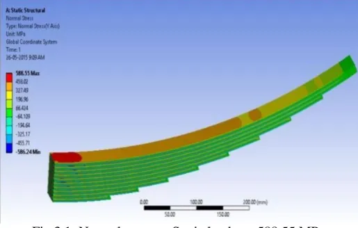
3.1.2 Static Load Results: For steel, At static load 2400N the Finite element results for normal stress, Von-misses stress and total deformation are shown in below figures.
Fig 3.1: Normal stress at Static load σ = 588.55 MPa
As we know that for the given loading conditions the leaf spring behaves like a cantilever beam. For cantilever beam the maximum bending stresses is developed at fixed support. From the Figure3.1, it is clear that the maximum induced stress 588.55 MPa is occurred at fixed end.
Figure 3.2: Von-misses stress at Static load σ= 521.26 MPa
Figure 3.3: Total deformation at Static load is 120 mm.
(www.dvpublication.com) Volume 3, Issue 1, 2018
Figure 3.4: Normal stress at Maximum load σ = 821.5 MPa
Figure 3.5: Von-misses stress at Maximum load σ= 727.59 MPa
Figure 3.6: Total deformation at Maximum load is 167.5mm 3.2 FEA Results for Tapered Steel Leaf Spring:
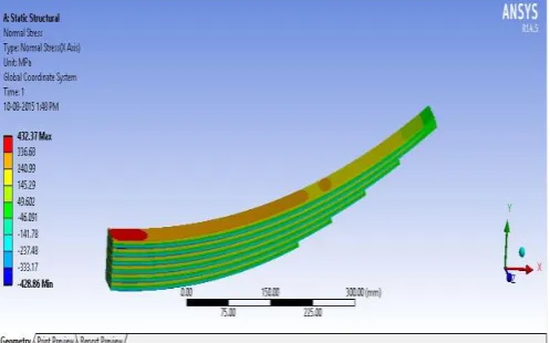
3.2.1 Static Load Results: At static load 2400N the Finite element results for normal stress, Von-misses stress and total deformation are shown in below figures.
(www.dvpublication.com) Volume 3, Issue 1, 2018
Figure 3.8: Von-misses stress at Static load σ= 380.78 Mpa
Figure 3.9: Total deformation at Static load 60.452mm
3.2.2 Maximum Load results: Similarly at maximum load 3350 the Finite element results for normal stress, Von-misses stress and total deformation are shown in below figures.
Figure 3.10: Normal stress at Maximum load σ = 603.52MPa
(www.dvpublication.com) Volume 3, Issue 1, 2018
Figure 3: Total deformation at Maximum load is 84.381mm 3.3 FEA results for Tapered Composite Leaf Spring:
3.3.1 E-Glass/Epoxy:
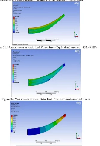
3.3.1.1 Static Load Results: At static load 2400N the Finite element results for normal stress, Von-misses stress and total deformation are shown in below figures. Normal stress σ = 158.05 MPa
Figure 31: Normal stress at static load Von-misses (Equivalent) stress σ= 152.43 MPa
Figure 32: Von-misses stress at static load Total deformation =75.418mm
(www.dvpublication.com) Volume 3, Issue 1, 2018 In the similar way evaluate the stresses and deformation at maximum load, and also find out the FEA results for E-Epoxy and carbon epoxy materials and those values are listed below.
Comparison of FEA and Analytical Method of Conventional Steel Leaf Spring: The results obtained from analytical procedure and finite elemental analysis of the conventional steel leaf spring was compared. The results of both procedures are nearly coincide with each other and are shown in below table.
Comparison FEA and Analytical method
Comparison of Stresses - FEA with Analytical method
Comparison of Deflection - FEA with Analytical method
Comparison of FEA Results Of Conventional and Tapered Leaf Springs: Tapered leaf spring made with steel and composite materials (like E-glass/Epoxy, S-glass/Epoxy and Carbon Epoxy) are analyzed by using ANSYS workbench 14.5. The results of normal stress, equivalent stress, deformation at static load and maximum load are shown in above figs. The FEA results of conventional leaf spring, Tapered leaf spring are compared and shown in below table.
Loading Condition
Stress in Mpa Conventional Tapered
Steel Tapered E-Glass Tapered S-Glass Tapered Carbon Static load 588.55 432.37 158.05 170.44 207.96
Max load 821.52 531.5 220.61 237.9 290.28
Comparison of Stress
Loading Condition
Deflection in mm Conventional Tapered
Steel Tapered E-Glass Tapered S-Glass Tapered Carbon
Static load 120 60.4 75.4 73.6 36.1
Max load 167.5 84.3 105.2 102.7 51.1
Comparison of Deflection 0 200 400 600 800 1000
STATIC LOAD MAXIMUM LOAD
BE N DIN G ST RE SS. MPa LOAD,N
Stress Vs Load
FEA ANALYTICAL METHOD
0 50 100 150 200
STATIC LOAD MAXIMUM LOAD
DE FLE CT ION ,m m LOAD,N
Deflection Vs Load
FEA ANALYTICAL METHOD
(www.dvpublication.com) Volume 3, Issue 1, 2018
Comparison of stress
Comparison of deflection
From table-9 and 10, the deflection and stresses of tapered composite leaf spring was less than that of tapered steel leaf spring and conventional steel leaf spring. The bending stress, total deformation values of all the three composite material are nearly equal. But in practical, based on the cost the E-Glass Epoxy is best suited for this application.
Comparison of Weight of Conventional and Tapered Leaf Springs: The weight of the conventional steel leaf spring is 16.77 kg, tapered steel leaf spring is 18.5 and tapered E-glass/epoxy leaf spring weight is only 4.72 kg.
Weight Comparison of leaf spring
From the above figure it can be clearly observed that the weight of the tapered E-Glass/Epoxy is low compared to the remaining leaf spring. Because E-Glass/Epoxy have less density compared to the steel.
Fatigue Life Calculation of Composite Leaf Spring: The analytical formula calculates the fatigue life of the component with made up of E-Glass/Epoxy composite material. Hwang and Han relation is
N = {B (1-r)} 1/C 0
200 400 600 800 1000
Static Load Maximum Load
S
tre
ss,MP
a
Load, N
Stresses Comparision
Conventional Tapered Steel Tapered E-Glass
Tapered S-Glass Tapered Carbon
0 50 100 150 200
Static Load Maximum Load
De
fle
cti
on,mm
Load, N
Deflection Comparision
Conventional Tapered Steel Tapered E-Glass
Tapered S-Glass Tapered Carbon
18.5 16.7
4.7 0
4 8 12 16 20
Wei
g
ht,
K
g
Weight Comparision
Tapered steel leaf spring
Conventional steel leaf spring
(www.dvpublication.com) Volume 3, Issue 1, 2018 Where,
N = No of cycles to failure B = 10.33
C = 0.140122
Applied stress level (r) = 𝑀𝑎𝑥𝑖𝑚𝑢𝑚 𝑠𝑡𝑟𝑒𝑠𝑠
𝑈𝑙𝑡𝑖𝑚𝑎𝑡𝑒 𝑡𝑒𝑛𝑠𝑖𝑙𝑒 𝑠𝑡𝑟 𝑒𝑛𝑔𝑡
S-N curve for Tapered composite leaf spring
From the S-N curve it is clearly observed that the tapered composite leaf spring, made up of E-Glass/Epoxy is withstand more than 10 lacks under the maximum stress 220.6 MPa and applied stress level of 0.2
Conclusion:
Compared the FEA results of conventional leaf spring and the tapered e-glass/epoxy leaf spring is found to have 73.2% lesser bending stress and 59.8% higher stiffness
The weight of the conventional steel leaf spring is about 16.7kg and the weight of the tapered steel leaf spring is about 18.5 whereas the tapered e-glass/epoxy leaf spring weight is about 4.7kg.
Therefore, it is concluded that the composite tapered leaf spring is an effective replacement for the existing conventional steel leaf spring in “Mahindra Commander 650 di” vehicle.
References:
1. Mahamood M Shokrieh, Davood Rezaei (2003). Analysis and optimization of a composite leaf spring, Composite structures, Vol.60, pp (317-325).
2. H.A. Al Qureshi (2001). Automobile leaf springs from composite material, Journal of Material Processing Technology, Vol.118, pp (58-61).
3. Pankaj Saini, Ashish Goel, Dushyant Kumar (2013), Design and analysis of composite leaf spring for light vehicles, IJIRSET, Vol.2 Issue.5, ISSN 2319-8753
4. ANSYS 14.5, ANSYS Inc.
5. M. Senthil kumar, S. Vijayarangan (2007). Design optimization and experimental analysis of composite leaf spring for light passenger vehicle, Advanced in vibration engineering, Vol.6, No.3, pp (175-183).
6. M. Senthil kumar, Design, manufacturing and testing of polymer composite multi leaf spring for light passenger automobiles – A Review.
7. Ashish V. Amrute , Edward Nikhil karlus, R.K. Rathore (2013), Design and assessment of multi leaf spring, Vol.1 Issue.7, pp (115-124).
8. M.L Aggarwal (2012). Modelling of shot peening parameter for weight reduction of EN45A spring steel leaf springs, AASRI Procedia, Vol.3, pp (642-645).
9. J.J. Fuentes, H.J. Aguilar, J.A. Rodrigue, E.J. Herrera (2009). Premature fracture in automobile leaf spring, Engineering Failure Analysis, Vol.16, pp (648-655).
10. J.P. Hou , J.Y. Cherruault, I. Nairne, G. Jeronimidis, R.M. Mayer (2007), Evolution of the eye- end design of a composite leaf spring of heavy axle loads, Composite structures, Vol.78, pp (351-358). 11. Y.S. Kong, M.Z. Omar, L.B. Chua, S. Abdullah (2104). Fatigue life prediction of parabolic leaf spring
under various road conditions, Engineering Failure Analysis, Vol.46, pp (92-103).
12. Dipendra Kumar Roy, Kashi Nath Saha (2013). Non liner analysis of leaf spring functionally graded materials, Procedia Engineering, Vol.51, pp (538-543).
0 200 400 600 800 1000 1200
-5000000 0 5000000 10000000 15000000 20000000
A p p li ed S tres s, M P a
Number of cycles to failure