RESEARCH
Experimental Study on the Mechanism
of the Combined Action of Cavitation Erosion
and Abrasion at High Speed Flow
X. Wang
1,2*, Y. A. Hu
1,2and Z. H. Li
1,2Abstract
A new experimental method on simulating the combined action of cavitation erosion and abrasion was proposed to investigate the erosion mechanism of overflow structure induced by the said processes. An automatic sand mixing device was invented for high-pressure and high-speed flow based on the characteristics of Venturi cavitation gen-erator and hydraulic Bernoulli principle. The experimental system for the combined action of cavitation erosion and abrasion was designed and constructed, and high-speed sand mixing flow only appeared in the test section. A series of tests on the combined and single action of cavitation erosion and abrasion on hydraulic concrete and cement was carried out by using the invented experimental device. Results show that the wear of concrete surface exhibited the combined characteristics of cavitation erosion and abrasion under their joint action. The damage degree of concrete surface under the combined action was more severe than that under a single action. The mass loss of concrete under the combined action was higher than sum of mass losses of concrete under two single actions. The promotion and enhancement between cavitation erosion and abrasion existed in high-speed sand mixing flow. A power exponen-tial relationship was observed between erosion mass loss and flow speed, and the velocity indexes approximated 4.5. Small and light sand particles easily follow water flow. Thus, the strong coupling effect of cavitation erosion and abrasion resulted from the presence of small sand particles. Given the different mechanisms of cavitation erosion and abrasion, presenting the skeleton structure formed by cavitation erosion was notably difficult under the action of abrasion. Meanwhile, abrasion wear easily occurred under the impact of cavitation erosion, and this result is due to the mechanism of the combined action of both processes.
Keywords: high speed flow, experimental method, cavitation erosion, abrasion, combined action
© The Author(s) 2019. This article is distributed under the terms of the Creative Commons Attribution 4.0 International License (http://creativecommons.org/licenses/by/4.0/), which permits unrestricted use, distribution, and reproduction in any medium, provided you give appropriate credit to the original author(s) and the source, provide a link to the Creative Commons license, and indicate if changes were made.
1 Introduction
Erosion on the overflow surface of discharge structure commonly occurs due to cavitation and abrasion at high speed flow. According to statistical data, 70% of discharge structures of large hydraulic projects in China suffer from cavitation erosion and abrasion damage (Wang et al.
2017). Figure 1 shows the erosions in the discharge hole of Liujiaxia hydropower station and spillway of Wanji-azhai hydropower station in the Yellow River. The figure
also features the coupling effect of cavitation erosion and abrasion. In recent years, the discharge flow speed of the high dam increased up to 50 m/s with increasing hydrau-lic project scale. Thus, the problem of cavitation erosion and abrasion will worsen (Wang et al. 2012). Studies on anti-erosion materials have focused on solving this prob-lem. Moreover, new anti-erosion materials are emerging. Therefore, the reasonable evaluation of erosion resistance performance of these new materials is crucial.
At present, several experimental methods are used to investigate the anti-abrasion or anti-cavitation perfor-mance of hydraulic concrete. For example, underwater steel-ball method and high-speed water sand method are usually used in anti-abrasion test (Wang et al. 2014). The Venturi cavitation generator (Tomov et al. 2016; Baylar
Open Access
*Correspondence: xwang@nhri.cn
et al. 2010) is commonly applied in anti-cavitation test. The relative anti-abrasion or anti-cavitation strength of different materials could be obtained on the basis of a series of comparison tests. Then, an improved mate-rial could be obtained. However, the current experimen-tal methods and test devices are mainly designed under the consideration of single erosion action (Hu et al.
2006; Horszczaruk 2005; Dular and Osterman 2008). The overflow surface of hydraulic engineering struc-ture is impacted by the combined action of abrasion and cavitation erosion at high-speed sand mixing flow. Studies have shown that mutual improvement and influ-ence of abrasion and cavitation erosion feature a com-plicated relationship (Huang and Yuan 2006; Chen et al.
2009; Wu and Gou 2013; Wang et al. 2018). Studies on the related mechanism had been carried out to investi-gate the coupled effect of cavitation erosion and abrasion (Toshima et al. 1991; Zhao et al. 1993; Tian et al. 1999; Sato et al. 1991; Xu et al. 2010; Johnson et al. 1995; Li
2006). Numerous different methods, such as placing solid particles in water inside a circle tunnel cavitation device, electric spark cavitation, and ultrasonic cavitation, were used. However, whether these experimental methods could reflect the real combined erosion behavior of cavi-tation and abrasion at high speed flow in hydraulic engi-neering remains unclear. When cavitation experiments with sand mixing flow are performed in the laboratory, the sand is usually added into the water tank, which pro-vides water for the test. Then, the sand mixing flow will be pumped into the main test section. Cavitation experi-ment with sand mixing flow had been conducted for the sand discharge hole in Xiaolangdi hydraulic engineering in China (Wang and Chai 1997). However, this method includes several problems. The sand mixing flow needs to pass through all the passages of the whole test system,
including pumps, pipe lines, valves, and flow meter. All these devices are subjected to wear under sand mix-ing flow. At the same time, sediment concentration is difficult to control. Thus, the experimental results are dissatisfactory.
Therefore, a new experimental method that could simulate the combined action of abrasion and cavitation erosion at high-speed sand mixing flow is needed to sci-entifically evaluate the erosion-resistant performance of hydraulic concrete under the combined action of these processes and study their mutual effect mechanism. In this study, 1:1 scale high-speed-flow experimental method and test device have been successfully developed to simulate the combined action of cavitation erosion and abrasion.
2 New Experimental Method for the Combined Action of Cavitation Erosion and Abrasion
The typical cavitation test device Venturi cavitation gen-erator was mainly employed for material cavitation ero-sion experiments (Fig. 2). High-pressure flow was formed before the test section of the device. Then, the high-speed negative pressure flow was generated at the location of the narrowest section, that is, the throat. Flow speed can increase up to 60 m/s. Strong cavitation occurred in the throat, and numerous cavitation bubbles were generated and proceeded to the enlarged downstream body with the flow. Under the positive pressure of the downstream, the cavitation bubbles will collapse near the surface of the concrete specimen set in the test section. Then, cavita-tion erosion would occur.
An automatic sand mixing device for high-pressure and high-speed flow without any additional power has been invented on the basis of Venturi cavitation generator. Then, new experimental method and device were formed
(a) Liujiaxia discharge hole (b) Wanjiazhai spillway
by the combined action of cavitation erosion and abra-sion. The core design of the automatic sand mixing device (Fig. 3) is as follows. According to the hydraulic Bernoulli principle, high flow speed corresponds to low pressure. Thus, the top of the sand bucket was connected to the upstream pressure-stabilizing tank. The pressure at the top of the sand bucket is called P2, which is equal to the
pressure of the stabilizing tank called P1, that is, P2= P1.
Thin tubes were used to connect the bottom of the sand bucket with the top of the test section before and near the throat. The pressure of the joint section (P3) is lower
than that of the tank as the flow speed of the joint sec-tion before the throat is higher than that of the stabiliz-ing tank, that is, P3 < P1. Therefore, P3 < P2, indicating that
the pressure at the bottom of the sand bucket is lower than that at the top. Thus, the sand will be automatically added to the main flow under pressure difference. Then, the high-speed sand mixing flow forms before the throat. When the mixing flow arrives at the throat, flow speed reaches the maximum, negative pressure appears, and strong cavitation occurs. As a result, the specimen set
in the enlarged section behind the throat was impacted by the double effect of cavitation erosion and abrasion at high-speed sand mixing flow. Meanwhile, for comparison with the effect of combined action, another specimen was set at the bottom of the test section, and it was impacted by abrasion of the sand mixing flow alone.
The new experimental device for the combined action of cavitation erosion and abrasion was set in the high-pressure and high-speed test system (Fig. 4). Several multi-stage pressurized centrifugal pumps were set to provide high-pressure and high-speed flow as experi-mental conditions. Sand recycling pool is located behind the test section to separate the sand from the mixing flow. The water will return to the water tank, and the sand will be recycled. The sand mixing flow only appeared in the test section to protect important devices, such as pumps, valves, flowmeters, and pipelines, from wear. One control valve was set in the pipe connecting the sand bucket and the test section to control sand content in the flow. Water sample was also obtained from the center of the vertical outlet pipeline to measure the sand content (Fig. 4). Thus,
Cavitation Throat
Upstream pressure stabilizing tank
P
Test section
Specimen
Fig. 2 Test device for cavitation erosion.
P
bucketSandUp specimen Sand
Sand added hole Top pipeline
P1
P3 P2 Valve
Control valve
Cavitation and abrasion Upstream pressure stabilizing tank
Test section
Down specimen
the sand content of sand mixing flow can be easily con-trolled, thereby laying the foundation for conducting dif-ferent condition tests.
3 Test Device and Test Procedure
The test system for the combined action of cavitation erosion and abrasion consists of a power system, stabiliz-ing tank, automatic sand mixstabiliz-ing device, test section, and sand recycling pool. The automatic sand mixing device serves as the core component, consisting of sand bucket, sand hole, top cover plate, exhaust pipe, observation win-dow, sand mixing pipe, and control valve. The top of the sand bucket was connected to the stabilizing tank. The sand mixing pipe was connected to the contraction seg-ment before the throat of the test section. At constant width of inlet contraction section, the pressure differ-ence between the top and bottom of the sand bucket was determined by the connection location of the sand
mixing pipe and test section. The pressure difference will decrease with increasing section height of the connection location. Thus, the sand mixing capacity was affected by the location of sand mixing hole. The width and height of the throat measured 1 and 10 cm, respectively. The sand mixing pipe was connected to the location of section at a height 2–3 cm before the throat.
The new test device has been constructed (Fig. 5). To ensure uniform sand mixing in the width direction, the sand mixing pipe was divided from one thick pipe into three thin ones in the width direction. These thin pipes access the contraction segment before the throat. The test condition was monitored by a flowmeter in the main pipe and pressure gauges set before and behind the test section. Three baffles were set to reduce water flow speed to complete sand sedimentation. According to the power system of the laboratory, the flow speed of the new test device could reach up to 60 m/s, and this value could
Down specimen
Valve
Measuring cup
P Pressure gauge
Outlet control valve
Sand recycling pool Sand bucket
Test section
Up specimen
Sand Sand added
hole
Backwater
Top pipeline
Sand P
Water tank
Pump Release valve
Flow control
valve Flowmeter
Pressure stabilizing tank Pressure gauge
Pump
Pump
Fig. 4 Expanded illustration of the experimental system.
(a) Test section (b) Sand recycling pool
meet the flow speed test requirement of prototype engi-neering conditions.
The new test method involves the following steps. (1) The valve set at the top of the sand bucket was opened, and sand was placed inside the bucket through the sand hole for the test. The valve was closed when the sand bucket contained sufficient amount of sand. (2) Two con-crete specimens were weighed before the test, placed in the test section, and then sealed. (3) The pumps were started to provide the flow for the test system, and the flow speed at the throat was controlled to achieve the test conditions. (4) The sand control valve was opened to mix the sand with at high speed flow. The sand control valve was adjusted to a suitable opening degree according to the measured sand content in the outlet. Then, the up specimen was impacted by the combined action of cavi-tation erosion and abrasion at high speed flow. The down specimen was impacted by abrasion. (5) After the test has reached a specified time, the concrete specimens were reweighed, and erosion rate was calculated according to mass loss, erosion area, and time. Then, the erosion fea-ture of the specimen surface was observed.
4 Test Device Performance and Test Effect
The automatic sand mixing device has been confirmed to possess stable working conditions. The new test device for the combined action of cavitation erosion and abra-sion exhibited the anticipated remarkable sand mixing capacity. Adjustment of sand content was flexible. The sand recycling pool also exerted the positive effect of separating sand from flow. Then, the test conditions of the high-speed sand mixing flow in the test section have been determined.
Concrete specimens were prepared for the erosion test to investigate the test effect of the new device and com-bined action mechanism of cavitation erosion and abra-sion. Table 1 shows the mix proportions of concrete. The flow speed of the test was 35 m/s, and the cavitation number of the throat was 0.216. The sand used for the test was selected from Yangtse River. The mineral com-position was mainly quartz and feldspar. The hardness was mainly Morse hardness 6–7. The morphology of par-ticles was mostly angular. The sand was sieved, and the particle size range of 0.16–0.315 mm was selected for the test. The sand content at high speed flow was controlled at 0.35 g/L, which was consistent with the natural river.
The test was conducted when the concrete specimens were cured for 96 days. Up specimen in the device was impacted by the combined action and the down speci-men was impacted just by abrasion of sands. During the test, the concrete specimens both up and down will be removed for mass weighing, and sand will be recycled and returned to the sand bucket every 30 min. Other erosion parameters could be obtained according to the mass loss of specimens. Surface morphology images can also be obtained for comparison. The erosion feature and wear procedure of concrete under the combined action of cavitation erosion and abrasion could be investigated. The cavitation erosion test of pure water was also con-ducted under the same test conditions to make a compar-ison with he coupled erosion. The test lasted for 3 h for each group. Table 2 and Fig. 6 provide the measured mass changes in the wear process of each specimen.
The test results show that wear appeared on the con-crete surface under the impact of high-speed sand mix-ing flow. The mass loss of concrete specimen gradually increased with the test time and followed a linear trend. Figure 7 shows the wear feature morphology of the sur-face of concrete specimens. Each image features a size of 15 cm length and 9 cm width. Image comparison indi-cated that the wear of concrete surface includes the fea-tures of cavitation erosion and abrasion under combined action. In the impact zone of cavitation erosion, a large erosion pit appeared on the concrete surface as a result of the separation of concrete surface mortar from the coarse aggregate. The cavitation erosion pit continually spread and deepened with prolonged test time. Increasing amount of mortar and coarse aggregate were stripped. On the other hand, the abrasion area was relatively large, and concrete surface erosion was relatively uniform. Abrasion erosion occurred layer-by-layer in the thickness direction. Numerous clear grooves were detected along the flow direction on the concrete surface, but no ero-sion pit with a size that of the cavitation impact area was observed. The images reflect two different mechanisms of cavitation erosion and abrasion. Cavitation erosion is mainly caused by the impact of cavitation bubble col-lapse, leading to continuous exfoliation of mortar aggre-gate and random distribution of erosion pits. Abrasion is mainly caused by friction and cutting of sand, resulting in uniform wear on the concrete surface and a directional corrugated groove.
Table 1 Mix proportions of concrete.
Water binder ratio
Sand
ratio (%) Cementitious materials
(kg/m3)
Content of fly ash (%)
Water
(kg/m3) Cement (kg/m3) Fly ash (kg/m3) Sand (kg/m3) Stone (kg/m3) Water reducer (%)
Compressive strength 60 days (MPa)
The table shows that the mass loss of specimen under combined action is greater than the sum of mass losses of single-abrasion and single-cavitation specimens under the same test conditions; the average increase in mass loss of combined action reached 61.4%. Cavitation ero-sion and abraero-sion at high-speed sand mixing flow pre-sented a certain degree of strengthening. Figure 8 shows the wear situation comparison of concrete surfaces under three action modes, that is, the combined action of cavi-tation erosion and abrasion, cavicavi-tation erosion only, and abrasion only after a 3 h test. The image size is the same as Fig. 7. Image comparison showed that the wear fea-tures of the combined action include those of the single actions of cavitation erosion and abrasion. Thus, devel-oped device could be satisfactorily used to carry out the research on erosion characteristics of high-speed sand mixing flow. In the corresponding area of cavitation ero-sion and abraero-sion, the degree of cavitation eroero-sion and abrasion damage under mixing action is notably greater than that of a single action, thus also reflecting the cou-pled effect between abrasion and cavitation. The erosion damage capability was enhanced under the combined action of these processes.
Another concrete material of different strength was tested with the new device for comparison. The compres-sive strength of 60 days was about 50 MPa. Under the same test condition, the concrete specimen was impacted for 3 h by the combined action. The surface feature of the specimen before and after the test were shown in Fig. 9. The same erosion characteristics can be found as above. The cavitation erosion area and abrasion area were dis-tinguished. So the effect of the combined action was proved again. As the lower strength of the concrete, the erosion was more serious. Especially the cavitation ero-sion made a obvious enhancement. The mass loss of the specimen was 31.0 g, which was 2.67 times of the mass loss of the concrete with 64 MPa strength.
5 Influencing Factor of Erosion
The P. I 42.5 cement was used to prepare cement speci-mens for testing to avoid the influence of complicated concrete components. The water-to-cement ratio was 0.4. Tests were conducted after curing the cement specimens for 96 days. Then, the combined action and abrasion-alone tests were performed to investigate the mechanism of coupling effect between cavitation and abrasion. The influences of flow speed and sand diameter were also investigated. The sand content of flow was controlled at 0.35 g/L. Three flow speeds, namely, 26, 34, and 43 m/s and three sand diameters, namely, 0.08–0.16, 0.16–0.315, and 0.315–0.63 mm (0.12, 0.24, and 0.48 for medium diameters, respectively) were selected for the test. Two specimens were tested for each time points. The top specimen was impacted by the coupled action of cavita-tion and abrasion. The bottom specimen was impacted by abrasion alone in the horizontal direction. Figure 10
displays the morphology images of the specimens before the test, under abrasion alone, and under the combined action of the two processes. The characteristics under abrasion alone and combined action were similar to the aforementioned results on concrete. The erosion process Table 2 Wear parameters.
Test time/h Specimen mass/g Mass loss/g
Cavitation
and abrasion Abrasion Cavitation Cavitation and abrasion Abrasion Cavitation
0.0 4785.1 4731.2 4794.0 0 0 0
0.5 4783.5 4731.6 4793.5 2.6 1.1 0.5
1.0 4781.5 4730.5 4793.3 4.6 2.2 0.7
1.5 4779.8 4729.6 4793.1 6.3 3.1 0.9
2.0 4777.7 4728.9 4792.9 8.4 3.8 1.1
2.5 4776.2 4728.0 4792.4 9.9 4.7 1.6
3.0 4774.5 4727.4 4792.1 11.6 5.3 1.9
0 2 4 6 8 10 12 14
0.0 0.5 1.0 1.5 2.0 2.5 3.0 3.5
Erosio
nm
as
sl
os
s/
g
Test time / h
Combined action of cavitation erosion and abrasion abrasion action only
Cavitation erosion action only
was stable, and the results are reliable as the specimens were prepared by pure cement.
The relationship between erosion mass loss and flow speed was obtained (Fig. 11). The sand size of 0.16– 0.315 mm diameter was selected for the test. The erosion mass losses caused by abrasion alone and the combined action of cavitation erosion and abrasion increased the flow speed. A power exponential relationship was
observed between the erosion mass loss and flow speed, and the velocity indexes all approximated 4.5.
Figure 12 shows the relationship between the erosion mass loss and sand size; this relationship was obtained based on a 2 h experiment using abrasion alone and com-bined action of cavitation erosion and abrasion under three kinds of sand particles with different sizes. The flow speed was fixed at 43 m/s. Results show that erosion capacity increased with sand particle size, whereas erosion mass
(a) 0 h (b) 0.5 h (c) 1.0 h
(d) 1.5 h (e) 2.0 h (f) 2.5 h
(g) 3.0 h
Cavitation erosion area
Abrasion area
Fig. 7 Concrete wear process under the combined action of cavitation erosion and abrasion.
(a) Combined action (b) Abrasion only (c) Cavitation erosion only
(a) Specimens before the test (b) Specimens after the test
Abrasion area Cavitation erosion area
Fig. 9 Surface feature comparison before and after test (test time: 3 h).
(a) Specimens before the test
(b) Specimens under abrasion alone (2 h)
(c) Specimens under combined action (2 h)
loss decreased with increasing sand particle size under the coupled action. This phenomenon is closely related to the flow pattern of sand particles in the flow. If sand particles are large and heavy, then following the water flow pre-sents difficulty, whereas sinking and impacting the bottom specimen are easy. If sand particles are small and light, then following the water flow is easy. Sand particles are more susceptible to the accelerated impact of cavitation flow. Thus, the strong coupled effect of cavitation erosion and abrasion resulted from the presence of small sand particles.
6 Mechanism of Coupling Effect of Cavitation Erosion and Abrasion
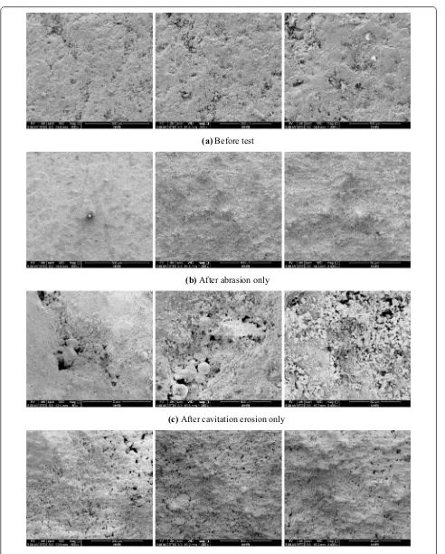
Advanced environmental scanning electron microscopy was used to observe the surface morphology of speci-mens before the test, after abrasion alone, after cavita-tion erosion alone, and after the combined accavita-tion the two processes to present the micro-features of erosion damage under different effects. Figure 13a shows the ini-tial surface morphology of the specimen before the test. Although the specimen possessed a flat surface, the mag-nification unexpectedly showed natural defects, includ-ing numerous sunken areas and occasional relatively deep holes. A small number of irregular particles were
attached to the surface, which is one of the reasons for cavitation and cavitation erosion on the surface of dis-charging concrete structure.
Figure 13b shows the micro-morphology of the speci-men surface after abrasion alone. Wavy or fish scales were observed on the abrasion surface from the large field of view, and the surface was smoother than the ini-tial state before the test. Moreover, no small particles were attached to the surface. After amplification, the specimen featured a clear and uneven surface micro-morphology and a continuous sheet structure. Occa-sionally, small erosion pits, which may be carried by the specimen itself, were detected.
Figure 13c shows the micro-morphology of the speci-men surface after cavitation erosion alone. The micro-morphology of cavitation erosion differed from that of abrasion. Cavitation erosion cannot only be observed macroscopically, but numerous small erosion pits can be found at the micro-level after magnifying the local ero-sion pit. After surface eroero-sion, a skeleton structure was formed by the accumulation of granular particles, and the relatively independent bulk structure of the surface dif-fered from the flake structure formed after abrasion. The results show the different mechanisms of cavitation ero-sion and abraero-sion.
Figure 13d displays the micro-morphology images of the specimens subjected to combined action of cavita-tion erosion and abrasion for comparison. The erosion under the coupled action presented dual characteristics of cavitation erosion and abrasion. The specimen surface exhibited a flake structure formed by the impact of abra-sion, whereas a large number of small holes were formed by cavitation erosion. Several independent bulk particles were found on the surface, showing not only the double effect of cavitation erosion and abrasion but also their promotion. The skeleton structure formed by cavitation erosion was difficult to present under the action of abra-sion. Cavitation erosion of the specimen was accelerated by abrasion. Meanwhile, abrasion wear easily occurred under the effect of cavitation. The coupled effect mecha-nism involves the combined action of vertical cavitation impact and horizontal cutting of sand mixing flow on the surface. Specimen erosion was generally accelerated by the interaction of cavitation erosion and abrasion. Figure 14 shows the schematic of the mechanism of the combined action of both processes.
7 Conclusions
1. The automatic sand mixing device was invented for high-pressure and high-speed flow based on the characteristics of Venturi cavitation generator and hydraulic Bernoulli principle. The experimental Mc= 1.91h10-6v4.37
Ma= 7.51h10-7v4.47
0 5 10 15 20 25 30
20 25 30 35 40 45
Erosio nm as sl os s/ g
Flow speed / m.s-1
Combined action Abrasion alone
Fig. 11 Relationship between erosion and flow speed.
0 10 20 30 40 50 60 70 80 90
0.0 0.1 0.2 0.3 0.4 0.5 0.6
Erosio nm as sl os s/ g
Average diameter of sand / mm
Combined action Abrasion alone
(a) Before test
(b) After abrasion only
(c) After cavitation erosion only
(d) After the combined action of cavitation erosion and abrasion
system for the combined action of cavitation ero-sion and abraero-sion was designed and constructed, and high-speed sand mixing flow only appeared in the test section. The developed experimental device could reasonably simulate the combined action of cavitation erosion and abrasion, thereby providing a valid way to investigate the mechanism of their com-bined action.
2. A series of tests on the combined action of cavita-tion erosion and abrasion and their single accavita-tion on hydraulic concrete was carried out with the invented experimental device. The results show that the wear of concrete surface featured the characteristics of both cavitation erosion and abrasion under their combined action. The damage degree of the concrete surface under the combined action was more severe than that under a single action. The mass loss of con-crete under the combined action was higher than sum of mass losses of the concrete under two single actions. The promotion and enhancement between cavitation erosion and abrasion existed in high-speed sand mixing flow.
3. The erosion mass loss caused by abrasion alone and the combined action of cavitation erosion and abra-sion increased with flow speed. A power exponential relationship existed between erosion mass loss and flow speed, and the velocity indexes all approximated 4.5. Small and light sand particles easily followed the water flow and were susceptible to accelerated impact of cavitation flow. Thus, the strong coupled effect of cavitation erosion and abrasion resulted from the presence of small sand particles.
4. As a result of the different mechanisms of cavitation erosion and abrasion, the skeleton structure formed by cavitation erosion was difficult to present under the action of abrasion. Cavitation erosion was accel-erated by abrasion. Furthermore, abrasion wear eas-ily occurred under the impact of cavitation, that is, through the mechanism of the combined action of cavitation erosion and abrasion.
Acknowledgements
Thanks to Materials & Structural Engineering Department of NHRI (China) for SEM analysis.
Authors’ contributions
All authors contribute equally. All authors read and approved the final manuscript.
Funding
The financial support from the National Natural Science Foundation of China (Grant Nos. 51479124, 51779151).
Availability of data and materials
The data sets supporting the results of this article are included within the article and its additional files.
Competing interests
The authors declare that they have no competing interests.
Author details
1 State Key Laboratory of Hydrology-Water Resources and Hydraulic Engi-neering, Nanjing Hydraulic Research Institute, Nanjing 210029, China. 2 Key Laboratory of Navigation Structures, Nanjing Hydraulic Research Institute, Nanjing 210029, China.
Received: 21 June 2019 Accepted: 21 September 2019
References
Baylar, A., Ozkan, F., & Unsal, M. (2010). Effect of air inlet hole diameter of venturi tube on air injection rate. KSCE Journal of Civil Engineering,14(4), 489–492.
Chen, H. S., Wang, J. D., & Chen, D. R. (2009). Cavitation damages on solid surfaces in suspensions containing spherical and irregular microparti-cles. Wear,266(1–2), 345–348.
Dular, M., & Osterman, A. (2008). Pit clustering in cavitation erosion. Wear, 265(5–6), 811–820.
Horszczaruk, E. (2005). Abrasion resistance of high-strength concrete in hydraulic structures. Wear,259(1–6), 62–69.
Hu, X. G., Momber, A. W., & Yin, Y. (2006). Erosion wear of hydraulic concrete with low steel fiber content. Journal of Hydraulic Engineering,132, 1331–1340.
Huang, X. B., & Yuan, Y. Z. (2006). Mechanism and prediction of material abrasion in high-velocity sediment-laden flow. Journal of Hydrodynam-ics,18(6), 760–764.
Johnson, M. L., Mikkola, D. E., & Wright, R. N. (1995). Cavitation erosion and abrasive wear of Ni3Al alloys. Intermetallics,3, 389–396.
Li, S. C. (2006). Cavitation enhancement of silt erosion-an envisaged micro model. Wear,260(9), 1145–1150.
Sato, J., Usami, K., Okamura, T., & Tanaba, S. (1991). Basic study of coupled damage caused by silt abrasion and cavitation erosion. JSME Interna-tional Journal,57(539), 20–25.
Tian, L. Y., Ding, T., Chen, J. F., & Huang, J. T. (1999). The experimental study about bubble collapse in sediment-laden flow. Journal of Hydroelectric Engineering,1, 68–73.
Tomov, P., Khelladi, S., Ravelet, F., Sarraf, C., Bakir, F., & Vertenoeuil, P. (2016). Experimental study of aerated cavitation in a horizontal venturi nozzle. Experimental Thermal and Fluid Science,70, 85–95.
&DYLWDWLRQ
$EUDVLRQ
6XUIDFH $EUDVLRQ
&DYLWDWLRQ
6WUXFWXUH 6WUXFWXUH 6WUXFWXUH 6WUXFWXUH 6DQG
%XEEOH FROODSVH
Toshima, M., Okamura, T., Satoh, J., Usami, K., & Tanabe, S. (1991). Basic study of coupled damage caused by silt abrasion and cavitation erosion. Transactions of the Japan Society of Mechanical Engineers,57(539), 2186–2191.
Wang, H. S., & Chai, G. C. (1997). Cavitation and cavitation erosion of eccentric-hinge radial gate under silting water. Hydro-science and Engineering,3, 237–241. (in Chinese).
Wang, X., Hu, Y. A., & Luo, S. Z. (2017). Prototype observation and influencing factors of environmental vibration induced by flood discharge. Water Science and Engineering,10(1), 78–85.
Wang, X., Hu, Y. A., & Yan, X. J. (2018). Test on abrasion resistance and deforma-tion characteristics of top seal of high head valve. Engineering Mechanics, 35, 349–354. (in Chinese).
Wang, X., Luo, S. Z., & Hu, Y. A. (2012). High-speed flow erosion on a new roller compacted concrete dam during construction. Journal of Hydrodynamics, 24(1), 32–38.
Wang, X., Luo, S. Z., Liu, G. S., et al. (2014). Abrasion test of flexible protective materials on hydraulic structures. Water Science and Engineering,7(1), 106–116.
Wu, J. H., & Gou, W. J. (2013). Critical size effect of sand particles on cavitation damage. Journal of Hydrodynamics,25(1), 165–166.
Xu, W. L., Li, Q., Chen, H. S., & Chen, D. R. (2010). Erosion and abrasion on mild carbon steel surface by steam containing SiC microparticles. Wear, 268(11–12), 1547–1550.
Zhao, K., Gu, C. Q., Shen, F. S., & Lou, B. Z. (1993). Study on mechanism of com-bined action of abrasion and cavitation erosion on some engineering steels. Wear,162–164, 811–819.
Publisher’s Note