Vol. 2 Issue 8, August - 2016
Sensitivity analyses of parameters that affect
the lightning performance of distribution
networks with distributed generation
Vasiliki Vita
Department of Electrical and Electronic Engineering City University London
London EC1V 0HB, United Kingdom [email protected]
Theodoros I. Maris
Department of Electrical Engineering
Technological Educational Institute of Central Greece 334 40 Psachna Evias, Greece
Abstract—The paper presents sensitivity
analyses that have been conducted on modern distribution networks (with DG) in an effort to contribute to the more efficient lightning protection of them. Several parameters that play an important role in the lightning performance of distribution networks such as the lightning current peak magnitude, the surge arrester model, the size of distributed generation units and the grounding resistance have taken into account. Simulations have been conducted using the NEPLAN Electricity software tool. The obtained results could be very useful to the electric utilities’ design engineers in their efforts to develop new lightning protection schemes for the modern distribution networks (with DG).
Keywords—distributed generation; distribution lines; grounding resistance; lightning; lightning performance; NEPLAN software; surge arresters
I. INTRODUCTION
The last two decades are observed many developments in electric power systems with distributed generation (DG) to be one of the most important. DG is small scale generation units that mainly use renewable sources. They are interconnected with the electric power system near load centres, thus, directly to the distribution network. DG units are larger in number than the more massive conventional power stations (typically located closer to an energy source) and are linked to the introduction of bidirectional power flow, mainly in distribution network, but in transmission network as well. As a result, the overall perspective, the configuration of the traditional electric power systems and the networks’ operation, have been considerably reformed over the last years once DG was introduced into the electric network construction. All the above have resulted to many challenges that must be addressed such as control and protection of electric power systems and more specifically of distribution networks [1].
Lightning strikes and switching surges are the main factors of power supply interruptions and equipment damages and malfunctions. Shield wires, surge
arresters and increased insulation levels are the most used protective means, in order to secure the reliability of the system and reduce the overvoltage faults [2].
Several studies have conducted all over world in an effort to contribute in the more efficient lightning protection of distribution lines. In [3] the effectiveness of shield wires in lines lightning protection has been proved through numerous simulations altering the location of overhead ground wires. In [4] computer simulations and test results obtained from scale model experiments have been used in order to evaluate the effectiveness of shield wires in reducing the magnitudes of the surges induced by nearby strikes on distribution lines. An external ground design applied on a distribution system for lightning performance improvement has been proposed in [5]. Simulations were conducted for the evaluation of lightning in terms of pole top voltage, critical current and backflashover rate. The study results revealed that the proposed external grounding system design can reduce significantly the effects of lightning and in turn improves the reliability, an extremely useful inference, especially for areas with high lightning outage rates.
The protection of wood pole distribution lines using different surge arrester configurations and spacing was investigated in [6]. Surge arresters and shield wires were also considered in [7] in an effort to observe the impact on distribution lines’ lightning performance of the induced voltages and grounding resistance. Similarly, the influence of grounding resistance and pole topology in the distribution lines’ lightning performance was examined in [8], where two different distribution network types with and without shield wires were studied. The main observation was the great impact of soil resistivity variation on the backflashover of shielded lines, in contrast to unshielded one. Statistical approaches for distribution lines lightning performance studies have presented in [9] and [10]. The obtained results were in close consistency with filed data and several mitigation steps for lightning performance enhancement were suggested.
Vol. 2 Issue 8, August - 2016 influenced by the connected distributed generation
units. Similar conclusions were obtained in [12], where was presented that the connected distributed generation units modify the lightning performance of distribution lines equipped with surge arresters and that grounding resistance is an important factor that must be taken under serious consideration.
In the current paper are presented lightning performance studies on distribution networks connected with DG. Several parameters such as the lightning current peak magnitude, the surge arrester model, the size of distributed generation units and the grounding resistance have taken into account. The NEPLAN Electricity software tool has been used for the simulations. The obtained results aim to contribute in the more effective lightning protection and the reduction of the lightning failure rate of modern distribution networks connected with distributed generation units.
II. MODELLING DISTRIBUTION NETWORKS WITH DISTRIBUTED GENERATION
A. Distribution Lines
In general, distribution lines cannot be modelled as lumped elements, since some of the line parameters depend on frequency. For electromagnetic transient studies the equations used for the estimation of the parameters of the line for steady state analysis are not appropriate, so the line parameters must be computed using auxiliary subroutines available in different electromagnetic transients programs. The majority of the simulation tools use basic types of line models, i.e., constant parameter models and frequency-dependent parameter models. The first category includes positive and zero sequence lumped parameter representation, PI-section representation and distributed parameter (Bergeron model) line representation. In the frequency-dependent model category, the most used models are frequency dependent line models for transposed and untransposed lines using constant modal, frequency dependent modal or no modal transformation matrix.
Distributed and frequency dependent parameter models are best for transient studies. They use traveling wave solutions, which are valid over a much wider frequency range than PI-circuit models. JMarti frequency-dependent model is more appropriate for the study of lightning performance of distribution lines, since it improves the reliability and the accuracy of the obtained results by approximating the characteristic admittance and the propagation constant by rational functions, in order to convert from mode domain to phase domain [13].
The grounding resistance of the line is modeled as a lumped resistor, the wooden poles are modeled by a parallel combination of a resistor and a capacitor, while the insulators were modeled as voltage-dependent flashover switches [8].
B. Shield Wires
Overhead shield wires constitute the most common method, in order to improve the lightning performance and reduce the number of faults in distribution lines.
Their role is to intercept lightning strikes, that otherwise would terminate on the phase conductors. Shield wires offer effective protection, when low values of ground resistance are achieved. When lightning strikes the pole structure or overhead shield wire, the lightning discharge current, flowing through the pole and pole ground resistance, produces potential differences across the line insulation. If the line insulation strength is exceeded, flashover occurs, i.e., a backflashover. Since the pole voltage is highly dependent on the pole resistance, consequently grounding resistance is an extremely important factor in determining lightning performance [2].
C. Surge Arresters
The lightning performance of a distribution network can be improved by installing surge arresters. Surge arresters present high resistance for normal operating voltage and low resistance in case of overvoltage, in order to pass the lightning or switching current to the ground. Fig. 1 shows the cutaway of a typical surge arrester, which consists of the electrodes, the varistor column, an internal fiber glass and the external insulation.
Fig. 1. Surge arrester cut (1: electrodes, 2: fiber glass, 3: varistor column, 4: external insulator) [20].
The most used frequency dependent surge arresters models are the IEEE model [14], the Pinceti-Gianettoni model [15] and the Fernadez-Diaz model [16]. The last two models are simpler forms of the IEEE model.
The IEEE Working Group 3.4.11 [14] proposed the model of Fig. 2, including the non-linear resistances A0
and A1, separated by a R-L filter. For slow front surges
the filter impedance is low and the non-linear resistances are in parallel. For fast front surges filter impedance becomes high, and the current flows through the non-linear resistance Ao. L0 is associated
with magnetic fields in the vicinity of the arrester. R0
stabilizes the numerical integration and C represents the terminal-to-terminal capacitance. The equations for the above parameters are given as follows [14, 17, 18]:
L1 = (15 d) / n μΗ (1)
R1 = (65 d) / n Ω (2)
Vol. 2 Issue 8, August - 2016
R0 = (100 d) / n Ω (4)
C = (100 n) / d pF (5)
where:
d is the length of arrester column in meters, and
n is the number of parallel columns of disks.
Lo L1
C
Ro R1
Ao A1
Fig. 2. The IEEE model [14, 17, 18].
The Pinceti-Gianettoni model has no capacitance and the resistances R0 and R1 are replaced by one
resistance (approximately 1 MΩ) at the input terminals, as shown in Fig. 3 [15, 17, 18]. The non-linear resistors are based on the curves of [14]. The inductances L0
and L1 are calculated using the equations [15, 17, 18]:
n r r T r V V V V
L
) 20 / 8 ( ) 20 / 8 ( ) / 1 ( 0 2 4
1 μH (6)
n r r T r V V V V
L
) 20 / 8 ( ) 20 / 8 ( ) / 1 ( 1 2 12
1 μH (7)
where:
Vn is the arrester’s rated voltage,
Vr(8/20) is the residual voltage for a 8/20 10 kA lightning
current, and
Vr(1/T2) is the residual voltage for a 1/T2 10 kA lightning
current.
Ro
Lo
L1
Ao A1
Fig. 3. The Pinceti-Gianettoni model [15, 17, 18].
The advantage of this model in comparison to the IEEE model is that there is no need for arresters’ physical characteristics, but there is only need for electrical data, given by the manufacturer.
The Fernandez–Diaz Model is also based on the IEEE model, A0 and A1 are separated by L1, while L0 is
neglected (Fig. 4). C is added in arrester terminals and represents terminal-to-terminal capacitance of the arrester. This model does not require iterative calculations since the required data are obtained from the manufacturer’s datasheet. The procedure for the computation of the parameters is given in [16-18]. The V-I characteristics for A0 and A1 are calculated using
manufacturers’ data, considering the ratio I0 to I1 equal
to 0.02. The inductance L1 is given as:
1
1 nL
L (8)
where:
n is a scale factor, and
1
L
is given in [16], computing the percentage increase of the residual voltage as:100
20 8
20 8 1 2 ) / ( r ) / ( r ) T / ( r res V V V (%) V (9) where:
Vr(8/20) is the residual voltage for a 8/20 lightning current,
and
Vr(1/T2) is the residual voltage for a 1/T2 lightning current
with the nominal amplitude.
Ro
Ao A1
C
Lo
Fig. 4. The Fernandez-Diaz model [16-18].
D. Distributed Generation Units
The implementation of distributed generation (DG) in the modern distribution networks is uninterrupted and is expected to increase in the coming years due to the many advantages they present. Distributed generation that is mainly based on renewable energy sources, such as photovoltaics and wind generators, are mainly located near to consumer centres and provide a bidirectional flow [1]. In this paper, and for the simulations that have been conducted, DG units where modeled as synchronous generators that inject into the network only real power (PV type).
III. SIMULATION RESULTS
The simulation model of the under study distribution network, designed in NEPLAN is shown in Fig. 5. Data from a real distribution line of nominal voltage of 20 kV (phase-phase, rms) has been used. The examined distribution line of total length 8 km, has been considered as unshielded and has been divided in four different segments with length of 2 km each, in order different points to be defined (A, B, C, D, E) along its length. At these points surge arresters were installed and the developed overvoltages for each point were calculated. Each one of the three DG units connected at points A, C and E were generated real power of 500 kW [19].The distribution line uses porcelain insulators of basic insulation level (BIL) 125 kV.
Vol. 2 Issue 8, August - 2016
Fig. 5. Simulation model of unshielded distribution network with DGs.
A. Sensitivity Analysis for Lightning Current Peak Magnitude
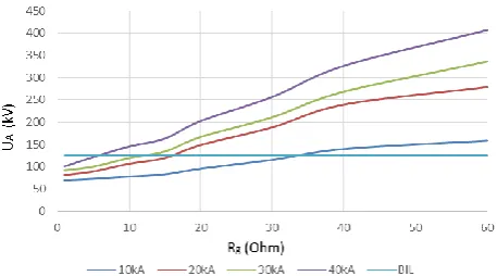
A sensitivity analysis has been conducted to the distribution network for four different lightning current peak magnitudes, i.e., 10 kA, 20 kA, 30 kA and 40 kA. The lightning discharges were applied at point A. In this analysis the distribution line’s grounding resistance was varying from 1 to 60 Ohms. Surge arresters were installed at points A, B, C, D, E.
Two case studies were considered. In the first one, none DG unit was connected to the network, while in the second one all three DG units were connected to the network. The obtained overvoltages at points A, C, E, for the first case study are shown in Figs 6-8 and for the second case study are shown in Figs 9-11.
Fig. 6. Developed overvoltages at point A for different peak lightning current magnitudes in relation to grounding resistance (no DG).
Fig. 7. Developed overvoltages at point C for different peak lightning current magnitudes in relation to grounding resistance (no DG).
Fig. 8. Developed overvoltages at point E for different peak lightning current magnitudes in relation to grounding resistance (no DG).
Fig. 9. Developed overvoltages at point A for different peak lightning current magnitudes in relation to grounding resistance (with DG).
Fig. 10. Developed overvoltages at point C for different peak lightning current magnitudes in relation to grounding resistance (with DG).
Network
Point A 20 kV
Point B 20 kV
Point C 20 kV
Point D 20 kV
Point E 20 kV
Line 1 Line 2
Load1 Load 2
Line 3
DG 1
Line 4
Vol. 2 Issue 8, August - 2016
Fig. 11. Developed overvoltages at point E for different peak lightning current magnitudes in relation to grounding resistance (with DG).
Based on the obtained results it can be observed that the variation of the grounding resistance had a proportional effect in the developed overvoltages. The overvoltages were attenuated as the distance from the lightning hit point was increased. The installation of the DG units to the network has shown that the developed overvoltages were significantly increased. In cases were the lightning hit point is close to the point that overvoltages are obtained it has been shown that the presence of DGs could result in a lightning fault for grounding resistance values of even a few Ohms, i.e., 10-20 Ohms. The overvoltages are much lower as the distance from the lightning hit point is increased but still they can result in lightning faults, since the obtained values are greater than the basic insulation level.
B. Sensitivity Analysis for Surge Arresters Models
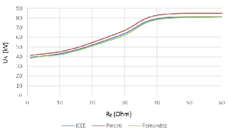
A sensitivity analysis has been conducted to the distribution network for the three different surge arresters models, i.e., the IEEE, the Pinceti-Gianettoni, and the Fernandez-Diaz model. Surge arresters were installed at points A, C, E. The lightning discharges with lightning current magnitude of 15 kA were applied at point C.In this analysis the distribution line’s grounding resistance was varying from 1 to 60 Ohms.
Two case studies were considered. In the first case study none DG unit was connected to the network, while in the second case study all three DG units were connected to the network. The obtained overvoltages at each one of the three different points (A, B, C) for the first case study (no DG) are shown in Figs 12-14, while for the second case study (with DG) are shown in Figs 15-17. It must be mentioned that although the overvoltages at points D and E have been calculated, these are not presented, since are symmetrical and identical with these in points A and B.
The obtained results have shown that all three surge arresters models have similar performance and the calculated overvoltages values are very close to each other. As the distance from the hit point increases the overvoltages are reduced. The presence of DGs results in higher overvoltages. Finally it has been shown that the effectiveness of each surge arrester model is different depending on the presence, or not, of DGs to the network, therefore a careful selection of surge arrester model to be used in the lighting studies of
electric utilities design engineers must be done, in an effort to obtain accurate results.
Fig. 12. Developed overvoltages at point A for different surge arresters models in relation to grounding resistance (no DG).
Fig. 13. Developed overvoltages at point B for different surge arresters models in relation to grounding resistance (no DG).
Fig. 14. Developed overvoltages at point C for different surge arresters models in relation to grounding resistance (no DG).
Vol. 2 Issue 8, August - 2016
Fig. 16. Developed overvoltages at point B for different surge arresters models in relation to grounding resistance (with DG).
Fig. 17. Developed overvoltages at point C for different surge arresters models in relation to grounding resistance (with DG).
C. Sensitivity Analysis for Surge Arresters Models
A sensitivity analysis has been conducted to the distribution network for three different combinations of distributed generation sizes, i.e., a) DGA=500 kW -
DGB=1 MW - DGC=500 kW, b) DGA=1 MW - DGB=500
kW - DGC=1 MW and c) DGA=1 MW - DGB=1 MW -
DGC=1 MW. The lightning discharges with lightning
current magnitude of 15 kA were applied at point A. In this analysis the distribution line’s grounding resistance was varying from 1 to 60 Ohms.
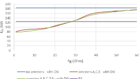
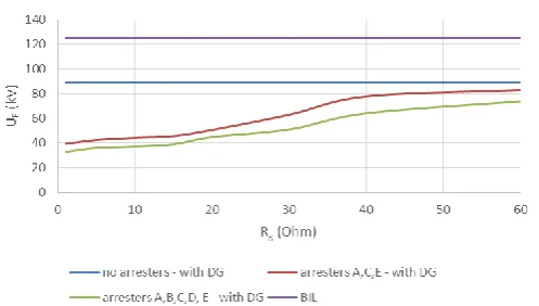
Three case studies were considered. In the first case study, arresters were installed at points A, B, C, D, E. In the second case study, arresters were installed at points A, C, E and in the third case study no arresters have been installed. The obtained overvoltages for point A and for all three different distributed generation size combinations are shown in Figs 18-20, the obtained overvoltages for point C and for all three different distributed generation size combinations are shown in Figs 21-23, while the obtained overvoltages for point E and for all three different distributed generation size combinations are shown in Figs 24-26
The obtained results have shown that the different sizes of the DG units connected with the distribution network produce different overvoltages at different points of the network that are proportional related to the size of the DG units. The higher the size of the DG, results in higher overvoltages that are abridged as the distance from the lightning hit increases. Moreover, it has been proven that low ground resistance quantities can result in the limitation of produced overvoltages, therefore special attention must be paid while designing
a grounding system, since it is the most effective measure for modern distribution networks’ lightning protection. Furthermore, it has been presented, that the presence of DGs in distribution networks demonstrates a significant impact in existing lightning protection systems. Thus, novel lightning protection schemes have to be applied, taking into consideration the constant and rising installation of DGs, in the effort to minimize or even eliminate the produced overvoltages caused by lightning strikes which in turn lead to unexpected faults and undesired power supply interruptions.
Fig. 18. Developed overvoltage at point A in relation to grounding resistance for DG sizes 500 kW - 1 MW - 500 kW.
Fig. 19. Developed overvoltage at point A in relation to grounding resistance for DG sizes 1 MW - 500 kW - 1 MW.
Vol. 2 Issue 8, August - 2016
Fig. 21. Developed overvoltage at point C in relation to grounding resistance for DG sizes 500 kW - 1 MW - 500 kW.
Fig. 22. Developed overvoltage at point C in relation to grounding resistance for DG sizes 1 MW - 500 kW - 1 MW.
Fig. 23. Developed overvoltage at point C in relation to grounding resistance for DG sizes 1 MW - 1 MW - 1 MW.
Fig. 24. Developed overvoltage at point E in relation to grounding resistance for DG sizes 500 kW - 1 MW - 500 kW.
Fig. 25. Developed overvoltage at point E in relation to grounding resistance for DG sizes 1 MW - 500 kW - 1 MW.
Fig. 26. Developed overvoltage at point E in relation to grounding resistance for DG sizes 1 MW - 1 MW - 1 MW.
IV. CONCLUSIONS
The paper presents the sensitivity analyses that have been conducted in a distribution network connected with distributed generation (DG) units in an effort to contribute to the more efficient lightning protection of them. Several parameters that influence significantly the efficiency of the protection systems and the developed overvoltages such as the lightning current peak magnitude, the surge arrester model, the size of distributed generation units and the grounding resistance were considered in the simulations that have been done using the NEPLAN Electricity software tool. The obtained results can be very useful to electric utilities and researchers in an effort to upgrade/modify the existing distribution networks’ lightning protection methods including the presence of distributed generation units.
REFERENCES
[1] V. Vita, T. Alimardan, and L. Ekonomou, “The impact of distributed generation in the distribution networks’ voltage profile and energy losses,” 9th IEEE European Modelling Symposium on Mathematical Modelling and Computer Simulation, Madrid, Spain, pp. 260-265, 2015.
Vol. 2 Issue 8, August - 2016 [3] J. Han, H.C. Seo, and C.H. Kim, “Analysis of
lightning overvoltage according to the location of overhead ground wire in Korea distribution system,” 2012 IEEE Vehicle Power and Propulsion Conference (VPPC), Seoul, Korea, pp. 1274-1276, 2012.
[4] A. Piantini, and J.M. Janiszewski, “The effectiveness of shield wires in reducing induced voltages from lightning electromagnetic fields,” 7th Asia-Pacific International Conference on Lightning (APL), Chengdu, China, pp. 666-672, 2011.
[5] K. Supanus, W. Thansiphraserth, N. Rugthaicharoencheep, and A. Phayomhom, “External grounding design to reduce effects of lightning damage in distribution system,” 7th IET International Conference on Power Electronics, Machines and Drives (PEMD 2014), Manchester, United Kingdom, 2014.
[6] R. Bhattarai, N. Harid, H. Griffiths, and A. Haddad, “Application of surge arresters for lightning protection of 33kV wood pole distribution lines,” 20th International Conference and Exhibition on Electricity Distribution, Prague, Czech Republic, Paper 0947, 2009.
[7] T. Thanasaksiri, “Improving the lightning performance of overhead distribution lines,” IEEE Region 10 Conference TENCON 2004, vol. 3, pp. 369-372, 2004.
[8] R.J. Cabral, D.S. Gazzana, R.C. Leborgne, A.S. Bretas, G.A.D. Dias, and M. Tello, “Analysis of distribution lines performance against lightning using ATP-EMTP,” 2012 International Symposium on Electromagnetic Compatibility (EMC EUROPE), Rome, Italy, 2012.
[9] P.N. Mikropoulos, and T.E. Tsovilis, “Statistical method for the evaluation of the lightning performance of overhead distribution lines,” IEEE Trans on Dielectrics and Electrical Insulation, vol. 20, no. 1, pp. 202-211, 2013.
[10] A.M. Busrah, and M. Mohamad, “The studies of the line-lightning performance of unshielded distribution lines”, International Conference on Electrical, Control and Computer Engineering (INECCE), Pahang, Malaysia, pp. 55-59, 2011.
[11] M.A. Araujo, R.A. Flauzino, O.E. Batista, L.A. Moraes, and C.H.R. Martins, “Protection of the distribution lines with distributed generation against lightning overvoltages in the context of smart grids,” 2013 World Congress on Sustainable Technologies (WCST), London, United Kingdom, pp. 36-41, 2013.
[12] V. Vita, L. Ekonomou, and C.A. Christodoulou, “The impact of distributed generation to the lightning protection of modern distribution lines,” Energy Systems, vol. 7, no. 2, pp. 357-364, 2016.
[13] J.R. Marti, “Accurate modeling of frequency-dependent transmission lines in electromagnetic transient simulation,” IEEE Trans on Power Apparatus and Systems, vol. PAS-101, no. 1, pp.147-155, 1982.
[14] IEEE Working Group 3.4.11, “Modeling of metal oxide surge arresters,” IEEE Trans on Power Delivery, vol. 7, no. 1, pp. 302-309, 1992.
[15] P. Pinceti, and M. Giannettoni, “A simplified model for zinc oxide surge arresters,” IEEE Trans on Power Delivery, vol. 14, no. 2, pp. 393-398, 1999.
[16] F. Fernandez, R. Diaz, “Metal oxide surge arrester model for fast transient simulations,” International Conference on Power System Transients (IPAT'01), Rio De Janeiro, Brazil, Paper 14, 2001.
[17] V. Vita, A.D. Mitropoulou, L. Ekonomou, S. Panetsos, and I.A. Stathopulos, “Comparison of metal oxide surge arresters circuit models and implementation on high voltage transmission lines of the Hellenic network,” IET Generation, Transmission and Distribution, vol. 4, no. 7, pp. 846-853, 2010.
[18] C.A. Christodoulou, L. Ekonomou, A.D. Mitropoulou, V. Vita, and I.A. Stathopulos, “Surge arresters' circuit models review and their application to a Hellenic 150 kV transmission line,” Simulation Modelling Practice and Theory, vol. 18, no. 6, pp. 836-849, 2010.
![Fig. 1. Surge arrester cut (1: electrodes, 2: fiber glass, 3: varistor column, 4: external insulator) [20]](https://thumb-us.123doks.com/thumbv2/123dok_us/8357933.1669812/2.595.349.525.350.493/surge-arrester-electrodes-fiber-varistor-column-external-insulator.webp)
![Fig. 2. The IEEE model [14, 17, 18].](https://thumb-us.123doks.com/thumbv2/123dok_us/8357933.1669812/3.595.42.278.124.254/fig-the-ieee-model.webp)