International Journal of Engineering Trends and Technology (IJETT) – Volume 67 Issue 6- June 2019
ISSN: 2231-5381
http://www.ijettjournal.org
Page 39
Design and Fabrication of a Palm Kernel Oil
Expeller Machine
Patrick Ejebheare Amiolemhen1, JoshuaAhuromeEseigbe2
1,2
Faculty of Engineering, Production Engineering Department, University of Benin, P.M.B 1154, Benin City, Nigeria.
Abstract
The aim of this work is to design and fabricate an effective palm kernel oil expeller machine.
A high torque and low rotational speed palm kernel oil expeller machine was developed by introducing an adjustable choke mechanism that permits adjustment of the back pressure to regulate the thickness and dryness of the pressed cake passing through the clearance between the barrel and the screw shaft. The machine components such as hopper, the expelling chamber; shaft; adjustable choke mechanism; pulleys; belts etc were designed and then fabricated using techniques such as cutting, welding, drilling, bending, and casting, etc.
The machine design enables cold palm kernel seeds to be processed without pre-treatment, the breaking and cooking operation being performed by the action of the screw shaft within the barrel of the unit. The machine has a nominal input capacity of approximately 280kg/hr when driven by a 10hp Electric motor.
Keywords: Screw shaft, adjustable choke, barrel, hopper, expeller chamber, press cake
I. INTRODUCTION
There is a universal demand for vegetable oil due to its increasing domestic and industrial uses. The rate of vegetable oil consumption is increasing compared to both animal fats due to its health implication (Akinoso, 2006).
Many methods of oil extraction exist, but in general these are based on one of four principles; which are: traditional wet rendering process; cage-type press; screw press and solvent extraction (Bredeson, 1983). He also considered two methods of pressure modulation; such as rotational velocity (ω) of the screw modulated to alter the pressure and movable press head to permits adjustment of the back pressure. Considerable efforts have been made in the past to improve the oil extraction efficiency of screw presses.Most of them have an optimization of process
variables such as applied pressure, pressing
temperature and moisture conditioning of the fed samples (Ohlson, 1992).
Small expellers that are power driven requiring about 8hp can process between 8 and 45 kg per hour of raw materials depending on the type of expeller (Kit, 1985).
According to Oyinlala et al (2004),a screw press usually requires a high torque and low rotational velocity to operate.
Hence, in this work, a high torque and low rotational speed palm kernel oil expeller machine is developed by introducing an adjustable choke mechanismthat permits adjustment of the back pressure. This in turn regulates the thickness and dryness of the pressed cake passing through the clearance between the barrel and the screw shaft.
II.MATERIALS AND METHOD
A. Materials
The materials used include: mild steel plate; medium carbon steel shaft; mild steel U- channel; angle bar; electric motor; speed reducer; etc.
Factors considered when selecting materials for fabrication of the machine include: durability of the materials; availability of the materials; ability to withstand corrosion; cost; ease of use; mechanical strength and rigidity; etc.
B. Methods
1) Design of machine components
Drive Power: The machine drive torque, T and power, P were computed as 1392.75Nm and 9.90Hp respectively using eqns. (1) and (2) as:
T = F × L × n
(1)
P =Fω𝜂 (2)
International Journal of Engineering Trends and Technology (IJETT) – Volume 67 Issue 6- June 2019
ISSN: 2231-5381
http://www.ijettjournal.org
Page 40
velocity of screw shaft=2πN60, N = screw shaft speed =40rpm and 𝜂 = electric motor efficiency = 0.79. 10hp electric motor with speed of 1440rpm is thus selected for this machine.
Electric motor/gearbox speed ratio: The input speed of the gearbox pulley, N2 was determined as 600rpm from eqn. (3):
N2= d1
d2× N1 (3)
where: N1 = electric motor speed = 1440rpm; d1 = electric motor pulley diameter = 125mm and
d2 = gearbox pulley diameter = 300mm.
Gearbox/screw shaft speed ratio: The screw press shaft speed, N3, was computed as 40rpm from eqn. (4) as:
N3 = g1
𝑟 × N2
(4)
where: N2= gearbox pulley speed = 600rpmand gr = gearbox speed ratio = 15
Tensions in the belt: The tension T1acting on the tight side of the belt and tension T2acting on the slack side of the belt were computed as 989.41N and 197.88N using eqns. (5) and (6). Olunlade el at (2018)as:
T1− T2=𝜋𝑑60𝑃
1𝑁1 (5)
T1+ T2=πd60Pfs
1N1 (6)
where: P = motor power = 7460W; d1 = motor pulley diameter = 0.125m; N1= speed of the motor = 1440rpm and
fs = service factor = 1.5 (heavy duty machine).
Power transmitted per belt: Power transmitted per belt was computed as 7459.99W using eqn. (7) as:
P = T1− T2 Vb (7)
where: T1 = tension acting on the tight side of the belt = 989.41N; T2= tension acting on the slack side of the belt = 197.88N;d1 = motor pulley diameter = 0.125mN1= speed of the motor = 1440rpm and
Vb= Velocity of belt = πd1N1
60 = 9.42m/s
Number of belt required for the drive: The number of belts required for the drive was computed as 2 using eqn. (8) as:
No of belt = Power transmitted per belt Designed power
(8)
where: Designed power = 7460W and power transmitted per belt =7459.99W.
Centre distance, C: The centre distance between motor and gearbox shafts was computed as 337.5mm using eqn. (9), Olunlade el at (2018) as:
C = 3r1 + r2 (9)
where: r1 = radius of motor pulley = 62.5mm and r2 = radius of gearbox pulley = 150mm.
Length of belt, Lb: Length of belt, Lbwas computed as
1365.27mm using eqn. (10) as:
L𝑏= 2C + π r2+ r1 + + r2−r1
2
C (10)
where: r1 = radius of motor pulley = 62.5mm, r2 = radius of gearbox pulley = 150mm and C = centre distance between motor and gearbox shafts = 337.5mm.
Belt specifications: The power transmitted per belt is 7459.99W, and hence we select the B series V-belts (power range of B V-belt range: 2 – 15kW per belt). The length of V-belt selected was 1415mm, which is nearer to Lb = 1365.27mm calculated (Khurmi and Gupta, 2009).
Pulley specifications: The pulley face width was calculated as 44mm using eqn. (11), Khurmi and Gupta (2009) as:
B = n − 1 e + 2f (11) Where: n = number of V-belt grooves on pulley, e =
19mm and f = 12.5mm, Khurmi and Gupta (2009).
Calculation of bearing pressure σbear on electric motor pulley hub: The torque being transmitted from the 125mm diameter electric motor pulley to the gearbox input shaft via the 300mm diameter pulley is vibratory and heavy. Moreover, the diameters of the electric motor and the gearbox input shafts are both greater than 22mm, hence the rectangular taper keys were selected for design, in accordance with BS 4235: part 1:1972. And, since the rectangular taper key is wider than it is deep, the key will fail in compression, before it will fail in shear (Melku et al (2018).
Hence, the bearing pressure on the key between the motor shaft and pulley was computed as 4.12N/mm2 using eqn. (12) as:
δbear =
2Mt
h−t1 ld dsm (12)
where: Mt = torque transmitted = 49470 Nmm, b = 16mm,
1d = length of key =6b = 96mm, h = 10mm, dsm = motor shaft diameter = 50mm and t1 = 5mm.
Since, δbear ≤ δbear all = 70N/mm2, the design is satisfactory from the standpoint of bearing pressure.
International Journal of Engineering Trends and Technology (IJETT) – Volume 67 Issue 6- June 2019
ISSN: 2231-5381
http://www.ijettjournal.org
Page 41
δbear = h−t2Mt
1 ld dsg
(13)
where: Mt = torque transmitted = 118730 Nmm, b = 16mm, 1d = length of key =6b = 96mm, h = 10mm, dsg = motor shaft diameter = 50mm and t1 = 5mm.
Since, δbear ≤ δbear all = 70N/mm2, the design is satisfactory from the standpoint of bearing pressure.
Calculation of Shaft Diameter: The shaft was designed from ductile materials. And the design of shaft of ductile materials based on strength is governed by maximum shear theory of failure.
Hence, applying ASME: code equation for the design of transmitting solid shaft under torsion and bending, the shaft diameter was computed as 53.29mm using eqn. (14) as:
d3= 16
πτall KbMb 2+ (KtMt)2
(14) Where:τall=
0.5ςy
sf = 60MN/m
2; σy = yield strength
for shaft material = 60MN/m2;sf= factor of safety 4; Kt = combined shock and fatigue factor applied to torsional moment = 1.0; Kb = combined shock and fatigue factor applied to bending moment = 1.5;Mt = Torque on shaft = 1780.94Nm and Mb = bending moment on shaft = 52.5Nm.
Calculation of Angular Deflection of Shaft: The design of shaft for rigidity was based on the permissible angle of twist α. The permissible angle of twist, α varies between 0.30/m ≤ α < 30/m, line shafting. And the permissible angle of twist was computed as 1.0o/m using eqn. (15) as:
α =584Mtl
Gd4
(15)
where: Mt = Torque on shaft = 1780.94Nm; l = length of shaft =1000mm; G = modulus of rigidity = 80 x 109N/mm2and d = shaft diameter = 60mm.
Calculation of lateral deflection of shaft: The deflection at the mid-point the simply supported shaft of length l = 1000mm in which W = 300N is at distance 350mm from each bearing support was computed as 2.33 x 10⁻⁵mm/m using eqn. (16) as:
δ = 48EIW l3 (16)
where: w = load on screw shaft = 300N; l = length of shaft between bearings 7000mm; E = Modulus of elasticity = 207 x 109N/m2 and I = π.d644=
6.36 x 10⁻⁷m4
Since δmax< δall, then the design is satisfactory on the basis of lateral deflection for machining shafting.
Calculation of critical speed of shaft: Using Rayleigh – Ritz equation the critical speed of the shaft was computed as 6196.24rpm using eqn. (17) as:
Wc= 60
2π g δ
(17)
where: δ = deflection at the mid-point the simply supported shaft = 2.33 x 10⁻⁵mm/m and g = acceleration due to gravity = 9.81m/s2.
Since, Wc = 6186.24rpm is far greater than 40rpm, then the design is satisfactory based on critical speed analysis.
Design of Screw on Shaft: The shaft is required to carry screw on its surface to enable it perform the crushing and conveying operations of the kernel seeds. The screw adopted for this design was the square thread made from 12.5 x 12.5mm mild steel rod. This was chosen as against having the screw machine on high carbon steel because of the availability of the rod and cost of machining. The major drawback is that the screw has to be replaced from time to time on the shaft because of wear. Tests show that the screw can last for 12-18 months.
Determination of the Pitch of the Screw: Since the screw size, h= 12.5mm square and shaft diameter, ds=60mm, then we have the following specifications: screw diameter, dm = ds + 2h = 85mm;internal diameter of barrel, di = ds + 2h +5 = 90mm; and pitch of the screw, p = 85mm
Reaction on the Screw Shaft: The reaction on the screw thread, R mainly due the torque being transmitted to the screw shaft and was computed as 41904.47N from eqn. (8) as:
R = 2Mt
dm 18)
where: dm = screw diameter = 85mm and Mt = torque transmitted = 1392.47Nm.
Maximum pressure in the Barrel: The maximum pressure in the press barrel σmax, was computed as
12.55N/mm2 from eqn. (19) as:
ςmax = πnd2R
mh (19)
where: dm = screw diameter = 85mm; h = the screw height= 12.5mm; n = number of screw pitches and R = reaction on the screw thread = 41904.47N.
Design of hopper: The volume of the hopper through which palm kernels are fed into the press barrel for palm kernel oil extraction was computed as 0.017m3 from eqn. (20) as:
International Journal of Engineering Trends and Technology (IJETT) – Volume 67 Issue 6- June 2019
ISSN: 2231-5381
http://www.ijettjournal.org
Page 42
where: a = top length of hopper = 300mm, b =baselength of hopper = 100mm, andH= height of hopper = 400mm.
Design of Barrel: The barrel interior was designed in such a way as to increase the friction between the palm kernel seeds and the barrel walls as the shaft rotates. This is done in order to reduce the degree of slippage and rotation of pressed cake with the shaft. The barrel is divided into two halves for easy regular
maintenance.
Design of Barrel Thickness: The thickness of the barrel was computed as 6.81mm by using the modified thin wall formula (Khurmi and Gupta, 2009), as:
t =P×dm
2×ςall + C
(21)
where: σmax =12.55N/mm2, σall =140N/mm2 and C= 3 (steel pipe).
Hence, we have: barrel thickness = 10mm and external barrel diameter, do = di + 2t = 90 + 2(10) = 110mm.
Design of Barrel arms thickness and width: Since the barrel is split into two halves, bolts are then needed to lock them together. Fig.1 shows a cross section of the barrel, barrel arms the formwork.
The barrel arm specifications are upper barrel arm width = 80mm; lower barrel arm width = 130mm; barrel arms thickness = 10mm; bolts sizes – M10 x 1.5 x 45 and number of bolts = 8
Fig. 1: Design of barrel
Design of the adjustable cone (Chock mechanism) and Screw Shaft: Fig.2 shows the cross section of the screw shaft, barrel and the adjustable cone.The choke mechanism, consist of an adjustable cone internally threaded and a hand wheel to turn the cone on the threaded section of the worm-shaft. The adjustable cone is located on the screw shaft at the end of the barrel to constrict the discharge of the pressed cake. The thread of the screw used for this design was the square thread, cut on the cone internally and on the shaft externally, respectively.The design of the choke mechanism for geometry and strength was done by
assuming that the pressed cake exerts pressure on the cone surface at half its full length and that this pressure is equal to the maximumbarrel pressure.
Fig. 2: The choke mechanism
Machine Capacity: The theoretical capacity of the expeller was determined as 280.6kg/hr using a modified form of the equation given by (Adetola et al (2014) as:
Qc= 60π4. dm2 − ds2 . p. N. φ. ρ (22)
where, dm = diameter of the screw thread = 85mm, ds = base diameter of the screw shaft = 60mm, p = screw pitch = 85mm, N = rotational speed of the screw shaft = 40rpm, φ = filling factor = 0.8, and ρ = bulk density of palm kernel seed = 604kg/m3.
Design of Flange Coupling: Fig.3 shows a cross section of the rigid flange coupling, flange hub and the screw shaft. The shaft speed is low and there is an accurate rigid axial alignment, hence the rigid flange coupling was adopted. The flange coupling is welded to a hub which is then held to the screw shaft by mean of bolts and nuts to allow for maintenance. The design of the flange diameter and the web thickness for geometry and strength was done by assuming that: bolts are finger tight and the load is transferred from one-half of the coupling to the other by a uniform shear stress in the shank of the bolt; the shaft is subjected to shock and fatigue and the bolts are uniformly arranged in the flange on bolt circle diameter. The results obtained are: pitch circle diameter = 125mm;flange diameter = 200mm; number of bolts = 6; web thickness = 15mm and bolt specification is: M12 x 1.5 x 60.
International Journal of Engineering Trends and Technology (IJETT) – Volume 67 Issue 6- June 2019
ISSN: 2231-5381
http://www.ijettjournal.org
Page 43
Fig.3: Coupling Design
Selection of Bearings: Bearings are selected based on load type and size. Due to the nature of load on the machine, tapered-roller bearing were selected in accordance with SKF General Bearings Catalogue (1987).
From the reference catalogue; series 32310 tampered-roller bearing of bore 50mm were selected. Overall radial load; due to the loads on shaft and the cantilever load imposed on the shaft by the coupling were determined. Also, the rated life of the more heavily loaded bearing at the support near the choke mechanism was determined. The rated life for the series 32310 tapered-roller bearing at this support was found to be:
Lh = 15,129.33hours
Since the basic rating life for a crushing machine working for 10hours or less is between 10,000 and 25,000 hours, then the bearing selected for use is very adequate.
Design of Foundation Bolts: The diameter of the foundation bolts used to hold the machine to the foundation platform was calculated by assuming that the bolts will fail in shear under the action of the axial force in the barrel, which tends to move the machine formed along the foundation platform and frictional force exists between the machine framework and the foundation platform.
Equating the resistance offered by n bolts (n = 4) with the axial forces less the frictional force between the machine framework and the foundation platform; we have; foundation bolt diameter to be 10mm.
Design of Foundation Block: When the machine is vibrating, the mass of the foundation should be three to five times the mass of the machine (Serinivasulu and Vaidyanathan, (1990). Hence, the weight of the foundation block is taken as equal to 4 times the weight of the machine.
Given: weight of the machine = 276kg and assuming the density of concrete to be 1500kg/m3, length of foundation block = 1800mm and width of foundation
block = 1200mm; then we have: depth of foundation = 426mm
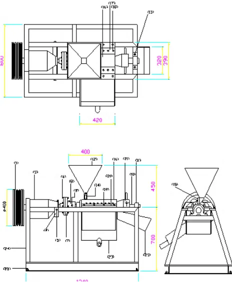
Description of the Machine: The detailed drawings of the palm kernel oil expeller machine are shown in and 5.The machine consists of different parts such as: the hopper; the frame; the barrel, the electric motor, the pulleys, the gearbox or speed reducer, the screw shaft, the adjustable cone, the bearings, the oil and press cake receptacles. The Palm kernel oil expeller machine consists of: the hopper shaped as a truncated frustum of a pyramid, with top and bottom having rectangular forms, is mounted on the barrel with shut off slide; the framework of outline dimension 1320mm long x 800mm high x 800mm wide; bolted to the foundation platform; two pulleys (125mm diameter at the electric motor shaft and 300mm diameter at the gearbox of input shaft); a gearbox of speed ratio 15:1; a rigid flange coupling between the gearbox and the screwshaft; a screwshaft of length 1000mm and diameter 60mm, coupling to the gearbox; a barrel with two arms (80mm and 130mm wide respectively) and length 450mm and diameter (90mm internal and 110mm external); the choke mechanism screwed to the screw-shaft at the end of the barrel; two, 32310 series tapered roller bearings, located at the two ends of the shaft; a hopper with shut off slides, mounted on the barrel at its beginning; and two trays underneath the barrel, one to collect palm kernel oil and the other to collect the pressed cake.
Working principles of the Machine: The kernels are fed to the screw press via a hopper mounted on the barrel with shut off slide. As the screw shaft rotates inside the cylindrical barrel, kernels are crushed against the barrel walls as well as conveyed toward the far end of the screw-shaft, where a steel adjustable choke mechanism presses the crushed kernels against the wall of the barrel to squeeze out the kernel oil. The kernel oil then flows out of the barrel through small drainage slots at its bottom into an oil tray, while the “pressed cake” discharges from the cone section into another tray. By regulating the clearance between the barrel and the adjustable cone (i.e. choke mechanism), the thickness and dryness of the pressed cake is regulated with this choke mechanism.
III. RESULTS AND DISCUSSION
International Journal of Engineering Trends and Technology (IJETT) – Volume 67 Issue 6- June 2019
ISSN: 2231-5381
http://www.ijettjournal.org
Page 44
using the various fabrication techniques such ascutting, welding, drilling, bending, and casting.
IV. CONCLUSION
The design and fabrication of a palm kernel oil expelling machine includes the construction of the hopper, the expelling chamber, the determination and selection of the appropriate belt and electric motor among other components.
The assembly of the various components is easy and unique allowing for efficient expelling of the palm kernel seeds by the worm carried on the rotating shaft enclosed by the barrel and at the same time ensuring the ease of maintenance of the whole machine. The kernel oil expeller machine designed and fabricated is effective and efficient and is capable of expelling 280.6kg of palm kernel seeds per hour when operated with a 10hp electric motor.
ACKNOWLEGDEMENT
This study was carried out in the Department of Production engineering, Faculty of Engineering, university of Benin, P.M.B. 1154, Benin City, Nigeria. We therefore, wish to thank all members of the Departmental workshop staff for their support and contributions.
REFERENCES
[1] Adetola, O. A., Olajide, J. O. and Olalusi, A. P. (2014). Development of a Screw Press for PalmOil Extraction. International Journal of Scientific & Engineering Research, Vol. 5, Issue 7, pp. 1416 – 1422.
[2] Akinoso R., Igbeka J., Olajanju T. and Bankole L., 2006. Modeling of Oil Expression from Palm Kernel (Elaeis guineesis Jacq.). Agricultural Engineering International: the CIGR Ejournal Manuscript FP 05 016. Vol. 8.
[3] Bredeson D.K., 1983. Mechanical Oil Extraction. Journal ofthe American Oil Chemists’Society. 60(2). 211-213. [4] Ezeoha, S.L., Akubuo, C.O. and Ani, A.O. (2012). Proposed
average values of some engineering properties of palm kernels. Nigerian Journal of Technology (NIJOTECH). Vol. 31, No. 2, pp. 167- 173.
[5] Khurmi R S, Gupta J K. (2008). A Textbook of Machine Design (Ed.). EurasiaPublishing House (PVT) Ltd. New Delhi. 1230 p.
[6] Kit, A. (1985). “Make Your Own Oil”. Royal Tropical Institute Magazine. Vol. 63. Amsterdam, Netherlands. [7] Melku A., Kirubel A., Melaku S., Meron B., Teshome D. M.
(2018). Design of Tire Changer. International Journal of Engineering Trends and Technology (IJETT). Vol. 64. No. 1.pp.1 – 23.
[8] Ohlson, I.S.R., 1992. Modern Processing of Rapeseed. Journal of the American Oil Chemists’ Society. Vol. 69. Pp. 195 – 198.
[9] Olunlade, B. A., Ogundola, J., Odiba, O. and Obaje, O. (2018). Development of a motorized sheet metal rolling machine. Advances in Research. Vol. 17(1), pp.1-9.
[10] Oyinlala A., Ojo A. and Adekoya L.O., 2004. Development of a laboratory model screw press for peanut oil expression. Journal of Food Engineering. 64(2). 217-227.
[11] Serinivasulu, P. and Vaidyanathan C.V, (1990). Handbook of Machine Foundation,2nd edition. [12] SKF General Bearings Catalogue (1987).
[13] TATA McGraw‐Hill Publishing Company ltd., New‐Delhi. [14] UNIFEM, (1987). Oil Extraction for Cycle Technology.
Handbook of United Nations Development Fund for Women. New York.
Table 1: Palm Kernel Oil Expelling Machine Parts List
N/S Parts Description No. Off
1 400mm diameter pulley 1
2 Taper (rectangular key) 1
3 Speed reducer 1
4 Speed reducer hanger 1
5 Speed reducer hanger bolts/ nuts (M12 x 1.75 x 50)
2
6 Flange coupling bolts/nuts (M12 x 1.75 x 60)
6
7 200mm diameter rigid flange
coupling
2
8 Flange hub 1
9 Flange hub bolts/nuts (M12 x 1.75
x 120)
2
10 Screw – shaft (1000mm) 1
11 Tapered roller bearings (Series 32310)
2
12 Hopper (3mm mild steel plate) 1
13 Bearings bolts/nuts (Ma2 x 1.75 x 60)
4
14 Hopper connector 1
15 Shut-off slide 1
16 Split barrel (two-halves) 1
17 Upper barrel arms 2
18 Barrel bolts/nuts (M16 x 2.0 x 60) 16
19 Framework bolts/nuts (M10 x 1.5 x
45)
8
20 Lower barrel arms 2
21 Adjustable cone (choke
mechanism)
1
22 Pressed cake discharge tray 1
23 Oil discharge tray 1
24 Framework 1
25 Foundation bolts/nuts (M12 x 1.75
x 400)
International Journal of Engineering Trends and Technology (IJETT) – Volume 67 Issue 6- June 2019
ISSN: 2231-5381
http://www.ijettjournal.org
Page 45
International Journal of Engineering Trends and Technology (IJETT) – Volume 67 Issue 6- June 2019