Published online November 27, 2014 (http://www.sciencepublishinggroup.com/j/com) doi: 10.11648/j.com.20140202.11
ISSN: 2328-5966 (Print); ISSN: 2328-5923 (Online)
Experimental performance analysis and improvement
techniques for RSSI based Indoor localization: RF
fingerprinting and RF multilateration
Md. Al Shayokh, Ugur Alkasi
Department of ECE, Yildiz Technical University, Esenler, Istanbul, Turkey
Email address:
[email protected] (M. A. Shayokh), [email protected](U. Alkasi)
To cite this article:
Md. Al Shayokh, Ugur Alkasi. Experimental Performance Analysis and Improvement Techniques for RSSI Based Indoor Localization: RF Fingerprinting and RF Multilateration. Communications. Vol. 2, No. 2, 2014, pp. 15-21. doi: 10.11648/j.com.20140202.11
Abstract:
In this paper, Performance improvement techniques for two popular RSSI based indoor localization methods have been studied experimentally by using Wi-Fi modems. The improvement of RF Fingerprinting and RSSI Multi-lateration methods have been suggested from different aspects for both line-of-sight (LoS) and non-line-of-sight (nLoS) medium in an indoor environment. Various testing scenarios have been examined for comparison of the two methods, as the performance level in RF Fingerprinting is mainly depend on the number of modems, as well as the density of training data and, the multilateration method is mainly depend on correctly modeling of the path loss exponent. Optimizing and defining a unique path loss exponent for each of the wireless transmitter modems, testing in a LoS and a nLoS medium, changing the number of transmitters, etc, have been tried and performance plots have been shown for comparison purposes.Keywords:
Indoor Localization, RSS (Receive Signal Strength), Lateration Technique, Wi-Fi Based Localization, LBS, RF Fingerprinting, Signal Strength to Distance Conversion1. Introduction
As computing and communications equipment becomes ever more powerful and cheaply available they are starting to pervade all areas of life. In order to make applications more useable products are being developed that have the ability to detect and respond to the context in which they are being used, for example the location of the user. Localization using radio signals was first introduced in the World War II to locate soldiers in emergency situation. During the war in Vietnam the Global Positioning System (GPS) was introduced and became available for commercial applications in the 90s of the last century. [1] Although it is the most popular positioning system for open outdoor environments, there is an unmet need for a reliable positioning system that can work indoors, where the microwave radio signals used by the GPS are greatly attenuated. [2] The need for LBS has been increasing everyday with several applications such as monitoring services for customers and helping them find their desired products, discounts and promotional offers in shopping malls, airports and other indoor environments.[3] Applications also include information services in museums, navigation services
Wi-Fi RSS based localization techniques offer no additional hardware, since usual Wi-Fi modems are usually available for most indoor shopping malls.[5] Comparing to techniques like TDOA or TOA the performance rate in RSS based methods remain insufficient which makes researcher to develop new techniques and improve the performance. [6] Previous study in literature has been proved that these techniques could be improved by various research techniques. Some experimental comparison study has been performed to find out the better solution. [7] In this work, the RSS measurements are used for improving the performance of two different techniques which are RF fingerprinting and multilateration techniques. The purpose of this paper is to present some techniques for the improvement of these two methods for finding a better accuracy rate and low error rate from a cost effective aspects in an indoor environment.
2. Literature Review
The proliferation of mobile devices and the growing demand for location aware systems that filter information based on current device location have led to an increase in research and product development in this field. In this section, we are highlighted the related techniques and products in which their main features, strength, and limitations are discussed. [8]
2.1. Navigation Radio Technologies
2.1.1. Satellite Global Coverage
It is been using on a Global Positioning System (GPS) providing a combination of territory-spatial positioning and navigation system that requires line of sight (LOS) in order to be functioning. Presently there are several global navigation satellite systems dedicated to civil positioning including the US NAVSTAR Global Positioning System, the Russian GLONASS, and the European Union’s Galileo.[9] The usefulness of satellite systems is that receivers can estimate latitude, longitude, and altitude to a high degree of accuracy. Due to the GPS characteristic of LOS, it is inoperable for the indoor environments where the LOS is invisible by ceilings and roofs.
2.1.2. Cellular Networks
A Cellular Communication Network is a system that allows mobile phones within a particular cellular range to wirelessly communicate with each other through large cell towers. This type of communication is based on the capability of the network to determine the position of a cell phone by identifying the cell tower that the device is connected at a given time.[10] The advantage of this technique is its ubiquitous distribution, easy implementation and the fact that all mobile cell phones support it. On the other side accuracy of this technique is very low due to the fact that cell towers can support ranges of 35 kilometers or more. In urban environments cell towers are distributed more densely.[11]
2.1.3. Wi-Fi
Wi-Fi stands for Wireless Fidelity that complies with the IEEE 802.11 standard. Nowadays, wireless connectivity is more prevalent than ever in our everyday lives. Each wireless Access point (AP) broadcasts a signal that can be heard by all devices within its range.[12] Wireless devices have the capability to measure the strength of this signal. This strength is converted to a number, known as Received Signal Strength Indicator (RSSI).[13]
2.1.4. Bluetooth
Bluetooth is a wireless communication that complies with IEEE 802.15 standard, similar to Wi-Fi except it is over short distances.[14] The devices can send a maximum of 3Mb/s. Implementation can be highly expensive.
2.1.5. Infrared
Infrared (IR) is a wireless networking specialized for the indoor positioning for limited range. IR has several technical limitations such as requires line of sight, the receiver affectivity by sunlight of a window room, in addition to its pricey installation and maintenance.[15]
2.1.6. Ultra Wide Band
Ultra Wide Band (UWB) has been pioneered for the use of a very low energy level for short range and high bandwidth communications using a large portion of the radio frequencies. [16]The natural strength of the UWB lies in its use of highly wide transmission bandwidths, which results in preferable capabilities which include accurate position location and ranging, lack of distinguished fading, high multiple accessibility, and easier material penetration.[17]
2.2. Positioning Techniques
Different techniques of signal based metrics are being in use for localization (device position determination) and have categorized the localization methods generally into five main methods:
With Cell Identification (Cell-ID):
In this method, transmitters or access points are partitioning a particular area into cells within these cells the receiver can be detected and positioned based on cell ID. However, this method is inaccurate, because it is hardly to determine where in the cell the receiver is located. [17]
The Angle of Arrival (AoA):
It determines the position of the device by calculating the angle towards the receiver from the transmitter using a directional antenna. This method requires a line of sight to spot the receiver, which is unreasonable to be implemented on indoor environments. [17]
Time of Arrival (ToA):
It determines the position of a device by calculating the distance from the transmitter to the receiver using the following formula: D = time x speed, where speed is a constant. [18] However, this method requires synchronization between the two imitated devices for a better accuracy.
Time Difference of Arrival (TDoA):
based on trilateration technique meaning it determines the receiver’s position based on calculating the intersection of the radii of the transmitters. [18]
Received Signal Strength (RSS):
The Received Signal Strength (RSS) which is also known as fingerprinting, where a radio map is being created. It composes of two phases, the offline (training) and online (tracking) phase. [18]The offline phase of fingerprinting is determining the signal characteristics at a given point and storing it in a database, following up the online phase by picking up the signal characteristics and compares it with the database to examine the place. Ordinarily, a filter is needed from the reflections, distortion and absorbance of the signals to increase the positional accuracy. [19]
RF based indoor localization. In this Paper, two popular methods of indoor localization have been experimentally analyzed in a real test bed. This paper presents the necessity of path loss modeling in an indoor environment and suggests necessary techniques to finding a better accuracy rate and low error rate from a cost effective aspects in an indoor environment.
3. Relationship between Received Signal
Strength and Distance
In a precisely given instant and place, the RSS values obtained by a device in a wireless network depend on a large number of unpredictable factors. Specifically, in a WLAN 802.11 network, small changes in position or direction may result in dramatic differences in RSS. Moreover, similar effects can happen even if the wireless devices remain static, due to the presence of moving objects that may interfere in the station-to-station propagation. It is clear that one of the factors influencing RSS values obtained by a wireless device is the distance between emitter and receiver, as this distance causes attenuation in RSS values.[20] It is mandatory to determine beforehand the sort of dependence present among those RSS values and the distance between the emitter and the receiver. This attenuation, caused by the distance between the emitter and the receiver, is known as path loss, and it is modeled to be inversely proportional to the distance between the emitter and the receiver raised to a certain exponent. This exponent is known as path loss exponent, path loss factor or path loss gradient. Other factors that affect RSS values are the multipath or fast fading and the shadowing or slow fading. These two factors can be modeled with Rayleigh or Rician and log-normal distributions.
4. Test Bed and Equipments
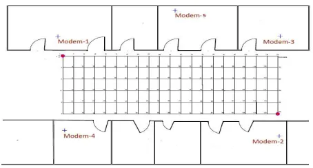
In this study, test bed has been selected at the School of Electrical and Electronics Engineering hallways in Yildiz Technical University. The test area has a dimension of about 6m by 24 m area of a ground floor. Normally, 5 modems can be detected in this area. During the experiment, Wi-Fi scanner tool on a Macintosh Computer with a high sensitivity Wi-Fi
receiver antenna is used for data collection.
Figure 1. The test location layout with positions of 5 modems
5. Experimental Analysis and
Performance Evaluation
5.1. RF Fingerprinting Method
measurements from one or more mobile devices. In other words, real time RSS values were measured and these data were compared against the previously collected offline RF fingerprints. Then, the mobile user’s location is estimated by using some classification algorithms in Matlab. The History based K-NN algorithm is used which provides low estimation error with the help of the nearest neighboring location data. K- NN algorithm is a non parametric learning method for classifying objects based on closest training data.
Figure 2. RSS value of 4 Wi-Fi Modems at different points
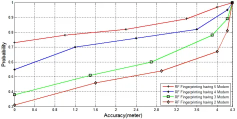
In this experiment, firstly collected real time data from the mobile user are compared against the offline database. With the help of a tracking system based on K-NN algorithms, RF Fingerprinting shows a result of 1.5 meter accuracy with a 55% a probability and 4.8 meter accuracy with 96% probability which is relatively fair. Later, another modem has been added to justify the performance in same condition. This time it shows a better accuracy rate with a 75% probability in 1.4 meter accuracy and 98% probability in 4.6 meter accuracy. Same experiment has been performed with the presence of 3 and 2 modems respectively. This time it has been noticed that the accuracy rate becomes relatively low than previous which led the importance of modem number for finding better accuracy. A Matlab graph shows the results of RF Fingerprinting methods in Figure 3.In second stage, the step interval considered as 1 meter to increase the density of training data in test bed. This time the density of collected database increased significantly. Later, having 4 modems real time data compared with the collected database data. This time a noticeable accuracy rate has been found. The accuracy rates go higher having 1.2 meter accuracy with 70% probability and 4.2 meter accuracy with 95% probability. Having 5 modems in test beds the result shows better result than the previous one with 1 meter accuracy with 78% probability and 4 meter accuracy with 97% probability. Same experiments have been done with the presence of 3 and 2 modems respectively. A Matlab graph in Figure 4 illustrates the results. This graph led to a new solution for improving the performance of RF Fingerprinting in an environment. It illustrates that having a maximum number of modes and a great density of data in a database which refers a relatively small step interval in RF Fingerprinting methods could give a preferably better solution than past.
Figure 3. Accuracy rate graph for different modems in test bed having a step interval of 1.2 meter
Figure 4. Accuracy rate graph for different modems in test bed having a step interval of 1 meter
5.2. RF Multilateration Method
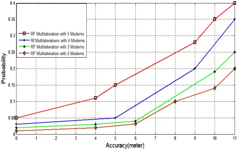
accuracy in 9 meter with a 25% has obtained. After modeling the path loss exponent for a LoS environment, RF multilateration methods have been performed in the same test bed with 4 modems in a LoS environment. Performance rate in accuracy shows poor result by using this technique. Using this method in a fairly longer test bed accuracy in 5 meter with a 5% probability and accuracy in 9 meter with a 25% has obtained. Later, same techniques have been performed using 5 modems. This time result in accuracy shows better but not satisfactory result. Using 5 modems accuracy of 4 meters with a 11% probability has been obtained. Same techniques have been performed using 3 and 2 modems respectively. This time the performance rate shows very poor result than previous one. This led us to a decision of using more modems for getting a better solution in an indoor environment to perform this method. Results have been shown by a graph in Figure 6. This graph illustrates and points out that the improvement of RF Multilateration could be improvised by increasing the modem numbers. Later, a smaller area of test bed has been selected to perform the same methods. This time the test bed dimensions considered 5.2 meter by 10.4 meter in a classroom of Electrical Electronics Faculty at Yildiz Technical University. In this stage, better accuracy results have been obtained than previous test by using 5 modems. This time the interval of distance has taken smaller than previous test.
Figure 5. Path Loss exponent modeling for LoS environment
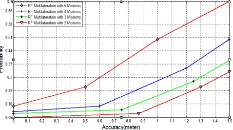
Accuracy performance shows a better result with an accuracy of 0.5 meter with an accuracy of 25%. By decreasing the modem in the experiment it has been found that the performance is relatively lower in this method. Results have been shown in Figure 7. This graph indicates that a better performance could be obtained in RF Multilateration by confining the test bed and step interval relatively small. Later to justify the performance in a nLoS system, same techniques has been performed with a nLoS environment considering different obstacles like walls, windows, human body reflection etc. At some specific or marked place which is especially behind the obstacles has been chosen and data has been measured. In this experiment most of the obstacles are considered as thick walls. Later, same techniques have been performed using 5 modems. This time result in accuracy shows better but not satisfactory result. Using 5 modems accuracy of 4 meters with a 11% probability has been obtained.
Same techniques have been performed using 3 and 2 modems respectively. This time the performance rate shows very poor result than previous one. This led us to a decision of using more modems for getting a better solution in an indoor environment to perform this method. Results have been shown by a graph in Figure 6. This graph illustrates and points out that the improvement of RF Multilateration could be improvised by increasing the modem numbers. Later, a smaller area of test bed has been selected to perform the same methods. This time the test bed dimensions considered 5.2 meter by 10.4 meter in a classroom of Electrical Electronics Faculty at Yildiz Technical University. In this stage, better accuracy results have been obtained than previous test by using 5 modems. This time the interval of distance has taken smaller than previous test. Accuracy performance shows a better result with an accuracy of 0.5 meter with an accuracy of 25%. By decreasing the modem in the experiment it has been found that the performance is relatively lower in this method. Results have been shown in Figure 7. This graph indicates that a better performance could be obtained in RF Multilateration by confining the test bed and step interval relatively small. Later to justify the performance in a nLoS system, same techniques has been performed with a nLoS environment considering different obstacles like walls, windows, human body reflection etc. At some specific or marked place which is especially behind the obstacles has been chosen and data has been measured. In this experiment most of the obstacles are considered as thick walls. Considering this condition, it has been noticed that the collected RSS value in a LoS medium and an nLoS medium varies significantly. Previously, in literature same path loss exponent has been used to find out accurate position using RF Multilateration method in an nLoS system. It has been found that to model path loss exponent for every modem is quite difficult work. To model path loss exponent, measurements has been taken for each modem separately in a LoS and an nLoS system.
Figure 6. Performance test of RF Multilateration in test bed
Figure 7. Performance test of RF Multilateration in test bed with a small area and small step interval
-Pr (d) = PL (d0) + 10n Log (d/d0) (1)
Where,
Pr (d): receive signal strength at distance d PL(d0): offset loss at reference point n:pathloss exponential
d0: distance from transmitter to the receiver reference
d:distance between transmitter to receiver
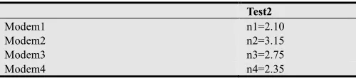
In this stage, using this formula different path loss exponent for different modems has been found. As an example, to find out the path loss exponent using this formula, the value obtained as 2.10 which is shown in Figure 9.By using the same techniques path loss exponent for other modes are obtained which is shown in Table-1.To justify the performance, at first path loss exponent is modeled in general for all modems in an nLoS medium. The path loss exponent n
is considered in an nLoS medium with a value of 3.4 (n=3.4). Figure 10 shows Matlab graph of the obtained path loss exponent in an nLoS medium. Later, performance test has been done by using this obtained value. It has been found that the obtained result was not satisfactory. By using same path loss exponent, an accuracy of 2 meter with a 3% probability has been obtained.
Figure 8. RSS value in Los and nLoS medium
Figure 9. Path loss exponent modeling for Modem 1 in nLoS environment
Figure 10. Path loss exponent modeling in nLoS environment (distance [m] vs. RSS[-dBm])
On other hand, using different path loss exponent in RF Multilateration the performance improves significantly with an accuracy of 2 meter having a 25% probability rate. Results have been shown in Figure.11. Figure 11 indicates the improvement of performance in RF Multilateration by using different value of n in an nLoS system. It should be mentioned that high error rate in RF Multilateration could be occurred because of multipath propagation, scattering, reflection and diffraction of substance. Moreover, it has been found that RF multilateration is suitable for small test bed area.
Table 1. Values of n for different modems
Test2
Modem1 n1=2.10
Modem2 n2=3.15
Modem3 n3=2.75
Modem4 n4=2.35
6. Conclusion
RF fingerprinting and multilateration use received wireless signal strength to determine the exact location of a mobile user in an indoor environment in different ways. In this paper, two popular methods of indoor based localization systems have been studied and performance improvement aspects have been suggested.
To improve RF Fingerprinting methods performance Offline measurements intervals must be smaller. The number of modem or Aps should be increased in
number.
The number of offline (training) data must be increase. To improve RF Multilateration methods performance
For a LoS system test bed area should be smaller. Number of modems must be increased in a LoS medium. For an nLoS system, path loss exponent for each modem
must be modeled.
Number of obstacles such as walls, windows etc. should be reduced in an nLoS system.
Acknowledgements
This work is funded by the Turkish R & D company named as RADARCOMM, Telecom & Energy to support the ongoing project of AVEA which is based on indoor localization. Authors of this paper want to thank Dr. Hakan Pasa Partal for his great and enthusiastic support.
References
[1] J. Schiller and A.Voisard, “Location Based Services”, Morgan Kaufmann Puv,2004.
[2] NICULESCU, D., BADRI, N. Ad hoc positioning system (APS) using AOA. In Twenty-Second Annual Joint Conference of the IEEE Computer and Communications Societies, INFOCOM 2003. San Francisco (USA), 2003, p. 1734 – 1743.
[3] B. Lee, String field theory,Hasan Buyruk, A.Kenan Keskin,Şeyma Şendil,Hasari Çelebi,Hakan P.Partal,Salih Ergut,Engin Zeydan,and omer Ileri, “RF Fingerprinting Based GSM Indoor Localization”, Signal Processing and Communications Applications Conference,SIU,2013.
[4] A Ward, A Jones, A Hopper, “A New Location Technique for Active Office”, IEEE Personal Communications, Vol 4, No 5, Oct 1997.
[5] SAYED, A. H., TARIGHAT, A., KHAJEHNOURI, N. Network based wireless location: challenges faced in developing techniques for accurate wireless location information. IEEE Signal Processing Magazine, 2005, vol. 22, no. 4, p. 24 – 40. [6] Ugur Alkasi, Md Al Shayokh , Hakan P. Partal, “An
experimental comparison study on indoor localization: RF fingerprinting and multilateration methods,” 10th international Conference on electronics, Computer and Computation, Ankara, Turkey, Nov. 7-9, 2013.
[7] Li,B.,Kam,J.,Lui,I.,& Dempstar,A.(2007). Use of Directional Information in Wireless LAN based indoor positioning.
Proceedings of IGNSS (International Global Navigation Satellite Systems Society) Symposium.Taipei:IEEE.
[8] Paramvir Bahl and Venkata N. Padmanabhan, "RADAR: an In-building RF-based User Location and Tracking System," in Joint Conference of the IEEE Computer and Communications Societies, vol. 2, 2000, pp. 775-784.
[9] Jeff Thurston, "GALILEO, GLONASS And NAVSTAR A Report on GPS for GIS People," GISCafe.com, 2002. [10] Vasileios Zeimpekis, George M. Giaglis, and George Lek, "A
taxonomy of indoor and outdoor positioning techniques for mobile location services," SIGecom Exchange, 2003.
[11] Bill R, Cap C, Kofahl M, and Mundt T, "Indoor and Outdoor Positioning in Mobile Environments," Geographical Information Sciences, pp. 91-98, 2004.
[12] Chiou, Y., C. Wang, S. Yeh & M. Su, “Design of an adaptive positioning system based on WiFi radio signals”. Computer Communications 32, pp. 1245-1254, 2009.
[13] http://www.bluetooth.com/Bluetooth/Technology/Works/ [14] Sinan Gezici et al., "Localization via ultra-wideband radios: a
look at positioning aspects for future sensor networks," IEEE in Signal Processing Magazine, vol. 22, no. 4, pp. 70-84, 2005. [15] Jeffrey R. Foerster et al. “A Channel Model for Ultrawideband
Indoor Communication”, 2003.
[16] Woo et al. (2011), Application of Wi-Fi-based indoor positioning system for labor tracking at construction sites: A case study in Guangzhou MTR. Automation in construction 20, pp. 3-13.
[17] Kolodziej, K. & J. Hjelm (2006), Local Positioning Systems. LBS Applications and Services. Boca Raton, FL, USA: CRC Press – Taylor & Francis Group.
[18] Zhang, D. et al., “Localization Technologies for Indoor Human Tracking”. Paper submitted to the 5th International Conference on Future Information Technology (FutureTech), May 2010, Busan, Korea.
[19] http://www.convep.com/malls.html