http://www.sciencepublishinggroup.com/j/se doi: 10.11648/j.se.20180602.13
ISSN: 2376-8029 (Print); ISSN: 2376-8037 (Online)
Analysis on High Data Rate Filter Design for Satellite
Communication
Su Mon Aye
1, Aye Than Mon
1, Hla Myo Tun
2, Zaw Min Naing
2, Win Khaing Moe
21
Department of Electronic Engineering, Technological University (Pathein), Pathein, Myanmar 2Department of Electronic Engineering, Yangon Technological University, Yangon, Myanmar
Email address:
To cite this article:
Su Mon Aye, Aye Than Mon, Hla Myo Tun, Zaw Min Naing, Win Khaing Moe. Analysis on High Data Rate Filter Design for Satellite Communication. Software Engineering. Vol. 6, No. 2, 2018, pp. 47-55. doi: 10.11648/j.se.20180602.13
Received: June 23, 2018; Accepted: July 5, 2018; Published: August 6, 2018
Abstract:
The paper presents the high date rate filter design for satellite communication using MATLAB. In this work, we considered only the numerical analysis for digital filter design based on the mathematical modeling of the filter design implementation. Result shows that operating frequency of IFIR filter is more than 5 times of that of IIR filter and when it is used in demodulator then the system operating frequency increase by 3 times to that of corresponding IIR filter based demodulator.Keywords:
High Date Rate Filter, DSP, Satellite Communication, Filter Design, Analysis1. Introduction
As a general design rule any module having feedback in its structure, limits the operating frequency of complete system. In high data rate applications it is very important to choose the suitable structure for each module in a system. Digital filters play an important role in communication system. They utilize maximum hardware resources and in turn decide the operating frequency of a DSP based communication system. A DSP based BPSK demodulator using FIR filter is an ideal choice for carrier/sub carrier demodulation in satellite. Because of huge hardware requirement for FIR filter, option of using upon the behavior of N-tap non recursive linear phase FIR when IIR or Interpolated FIR (IFIR) filters is explored. IIR filter has a advantage of programmability, but the operating frequency of the system is limited by its feedback loops. On the other hand IFIR is equivalent of FIR with reduced hardware and no feedback loop in structure. An IIR based BPSK demodulator that can go up to a data rate of 16Kbps for PCMIPSK/PM scheme has been realized. For some payload operations in satellite & also for ground application higher data rate demodulators are required. Using IFIR filter, the same demodulator can be used for those applications. The paper describes one of the applications of
IFIR filter in realizing the 500Kbps BPSK demodulator. In first section general design of an IFIR filter is discussed followed by description of an IR filter. There are many reasons why IFIR filters are very attractive for digital filter design. Some of them are:
1. Simple robust way of obtaining digital filters
2. Inherently stable when implemented non recursively
3. Free of limit cycles when implemented non recursively
4. Easy to attain linear phase
5. Simple extensions to multi-rate and adaptive filters 6. Relatively straight-forward to obtain designs to match
custom magnitude responses
7. Some vendors and specialized hardware only support FIR
8. Low sensitivity to quantization effects compared with many IIR filters
reduced if they are implemented using fast numerical algorithms such as the fast Fourier transform.
The IFIR filter can implement narrowband low pass filter design with significantly reduced computational workload relative to traditional FIR filters. The structure of an IFIR
filter design is illustrated in Figure 1. The input or excitation x (n) is bounded input signal. When the bounded input signal is processed according to the output or response by using IFIR filter system HIFIR (f) [1-11].
Figure 1. The Structure of an IFIR Filter.
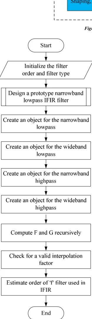
Figure 2. System Flowchart for IFIR Filter Analysis.
2. Flowchart of FIR Digital Filter Design
Analysis
According to the literature survey on the IFIR lowpass filter design analysis, the high data rate filter for satellite communication system can be developed with the appropriate design step. The system flowchart for IFIR lowpass filter analysis is illustrated in Figure 2. In this flowchart, there are a lot of processes to accomplish the IFIR low pass filter design. Firstly, the filter order and type are initialized and the subroutine from MATLAB is applied to design a propotype narrowband lowpass IFIR filter. And then the object for narrowband lowpass and high pass filter. The F and G values are recursively analyzed to estimate the “f” filter used in IFIR lowwpas filter analysis.
3. Development of IFIRMAIN.m Script
The main funtion for IFIR lowwpass filter design analysis are combined with the following instructions. The maximum filter order must be 6 and type of digital filter is “low”. The filter analysis can be accomplished to IFIR high data rate filter by applying the filter design tool in MATLAB [12-15].
[bup,bimg]=IFIRDESIGN(6,'low', [.12 .14], [.01 .001]); H = dfilt.dffir(bup); G = dfilt.dffir(bimg);
hfv = fvtool(H,G);
legend(hfv,'Unsmaples Filter','Image Suppressor Filter'); Hcas = cascade(H,G);
hfv2 = fvtool(Hcas);
legend(hfv2,'IFIR Filter Design');
4. Development of IFIRDESIGN.m
Script
maximum deviations or ripples (in linear units) specified in vector DEV. TYPE must be a string with either 'low' for lowpass designs or 'high' for highpass designs. F must be a two-element vector with passband and stopband edge frequency values. For narrowband lowpass filters and wideband highpass filters, L*F(2) should be less than 1. For wideband lowpass filters and narrowband highpass filters, L*(1-F(1)) should be less than 1.
DEV must contain the peak ripple or deviation (in linear units) allowed for both the passband and the stopband, i.e., it also must be a two-element vector. IFIDDESIGN returns a delay D that must be connected in parallel with the cascade of H (z^L) and G(z) in the case of wideband lowpass and highpass filters. This is necessary in order to obtain the desired response.
To design a prototype narrowband lowpass IFIR filter the instruction may have been modified as needed
[f,g] = narrowBandLp(L,F,DEV,optlevel,forceEven); switch designType,
case 'narrowBandLp',
% Create an object for the narrowband lowpass [f,g,d] = designnl(f,g,L);
case 'wideBandLp',
% Create an object for the wideband lowpass [f,g,d] = designwl(f,g,L);
case 'narrowBandHp',
% Create an object for the narrowband highpass [f,g,d] = designnh(f,g,L);
case 'wideBandHp',
% Create an object for the wideband highpass [f,g,d] = designwh(f,g,L);
end
To develop the designnl function, the creation of an object for the narrowband lowpass are needed to modify as follows:
% Upsample f, create F(z^L) f = upsample(f,L);
% Remove trailing zeros f = f(1:end - (L-1));
d = []; % Not used for narrowband lowpass
To create an object for the wideband lowpass and create two parallel branches, one with a narrowband highpass and one with a delay the -f is needed because of the negative sign of this branch entering the adder
d = [zeros(1,(length(f)+length(g)-2)./2),1]; % Delay To create an object for the narrowband highpass, the below instructions are as follows:
if rem(L,2), % Find F(-z) first f(2:2:end) = -f(2:2:end); end
% Now upsample f = upsample(f,L); % Remove trailing zeros f = f(1:end - (L-1)); % Find G(-z)
g(2:2:end) = -g(2:2:end); M = length(f) + length(g) - 2;
if rem(M/2,2) == 1,
% Must add a negative 1 factor to branch1 f = -f;
end
d = []; % Not used for narrowband highpass
To create an object for the wideband highpass and create two parallel branches, one with a narrowband lowpass (entering with a minus sign to the adder) and one with a delay the -f is needed because of the negative sign of this branch entering the adder.
d((length(f)+length(g)-2)./2+1) = 1; % Delay
To design a prototype narrowband lowpass IFIR filter, the lowpass response appropriate for firpm can be defined as
A = [1 1 0 0]; switch optlevel,
case {'simple','intermediate'}, if forceEven,
minStr = 'mineven'; else
minStr = 'minorder'; end
case 'advanced',
% Estimate required orders for F and G N1 = estimateifirford(L,F,A,DEV); N2 = estimateifirgord(L,F,DEV);
To test the min stopband attenuation, the system function H(z) can be got from the following instructions.
[H,w] = freqz(upsample(f,L)); H = H.*freqz(g);
To compute the gain value g for IFIR lowpass filter, there are two case for switch condition.
switch lower(optlevel), case 'simple',
s = warning('off', 'filterdesign:firgr:finalFilterOrder'); g = firgr(minStr, [0 F(2) 2./L-F(3) 1],A, [DEV(1)./2 DEV(2)]);
case 'intermediate',
To improve the order of G in some cases by including don't care regions, the following instruction can be used.
g = computeintermediateg(L,F,DEV,minStr);
To compute do care and don't care regions for g, the following instructions are needed.
Fg = gFreqIntervals(F,L); Ag = [1 1 zeros(1,length(Fg)-2)];
DEVg = [DEV(1)./2 DEV(2)*ones(1,(length(Ag)-2)./2)]; To analyze the recursive design for iterations, the old values of f and g are first initialize.
fold = [1,zeros(1,N1)]; gold = zeros(1,N2+1);
And the first iteration can be started as follows: gnew = iterateg(N2,L,fold,F);
fnew = iteratef(N1,L,gnew,F,DEV);
The limitation and range of maximum iteration are specified by 100 as shown in the following instructions.
And the old baselines are updated according to the new value of g based on the new values of f.
gold = gnew; % Compute new G
gnew = iterateg(N2,L,fnew,F); % Update old baselines fold = fnew;
% Compute new F
fnew = iteratef(N1,L,gnew,F,DEV); iter = iter + 1;
To check for increasing frequencies, the following instructions are applied to determine the design type and convert specification to narrow lowpass frequency range.
if any(diff(F) <= 0),
msg = 'Frequencies must be specified in increasing order.';
return; end
% Determine design type and convert spec to narrow lowpass
[Fout,forceEven,designType,DEV,msg] =
determineTypeNSpecs(L,designType,F,DEV); if ~isempty(msg),
return;
In the step of determine, appropriate algorithm to use for IFIR lowpass filter can be analyze by using the following instructions.
msg = '';
stropts = {'simple','intermediate','advanced'};
indx = find(strncmpi(optlevel,stropts,length(optlevel))); if isempty(indx),
msg = 'Unrecognized optimization level specified.'; return;
end
optlevel = stropts{indx};
To determine if lowpass or highpass, the following codes are applied.
designOpts = {'low','high'}; designIndx =
find(strncmpi(designType,designOpts,length(designType))); if isempty(designIndx),
msg = 'Design type must be ''LOW'' or ''HIGH''.'; return;
To determine if narrow-band or wide-band design, the switch case is very efficient method for IFIR lowpass filter analysis.
switch designType, case 'low', if F(2) < 1/2,
designType = 'narrowBandLp'; else
designType = 'wideBandLp'; Fout = [0,1-F(2),1-F(1),1]; DEV = fliplr(DEV); forceEven = 1; end
case 'high', if F(2) < 1/2,
designType = 'wideBandHp'; forceEven = 1;
else
designType = 'narrowBandHp'; Fout = [0,1-F(2),1-F(1),1]; DEV = fliplr(DEV); forceEven = 1; end
Finally, to check for a valid interpolation factor, the interperr instruction for switch case should be utilized as follows:
interperr = 'The interpolation factor L is too large for the frequency specs.';
switch designType,
case {'narrowBandLp','wideBandHp'}, if L*F(2) >= 1,
msg = interperr; return;
end
case {'narrowBandHp','wideBandLp'}, if L*(1-F(1)) >= 1,
msg = interperr; return;
end
5. Simulation Results for Comparison of
Unsampled and Sampled Filter
The simulation results for high data rate filter design are separated by two portions. They are response of unsampled and image suppressor filter analysis and response of IFIR filter. The first one is comparison of unsampled and sampled filter.
5.1. Magnitude Response for Unsampled and Image Suppressor Filter
Figure 3. Screenshot of Magnitude Response for Unsampled and Image Suppressor Filter.
The screenshot of magnitude response for unsampled and image suppressor filter is illustrated in Figure 3. This figure gives the very low transition width after sampling the unsampled filter condition. The normalized frequency for passband condition is approximately 0.3×π rad/sample. It is the acceptable range for IFIR filter design analysis.
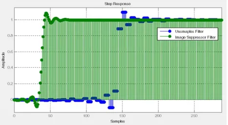
5.2. Step Response for Unsampled and Image Suppressor Filter
Similarly, the screenshot of step response for unsampled and image suppressor filter is shown in Figure 4. The steady state condition is around 75 samples after analyzing the IFIR lowwpass filter design. It is very close to good performance of filter evaluation.
5.3. Simulation Result of Magnitude and Phase Response Comparison
The screenshot of magnitude and phase responses for unsampled and image suppressor filter is mentioned in Figure 5. The phase response for unsampled filer is approximately -326.6314 radians and image suppressor filter is -4.658 radians respectively due to the increment of samples in filter analysis. These responses give the satisfactory results for IFIR lowpass filter design analysis for high data rate situation in satellite communication system.
Figure 5. Screenshot of Magnitude and Phase Responses for Unsampled and Image Suppressor Filter.
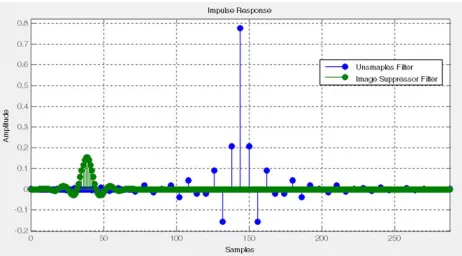
5.4. Simulation Result of Impulse Response
The screenshot of impulse response for unsampled and image suppressor filter is shown in Figure 6. It is very convenient response for high data rate filter analysis.
5.5. Simulation Results for IFIR Filter Design
The second one is the analysis of IFIR filter design for high data rate condition.
5.6. Magnitude Response for IFIR Filter
The screenshot of magnitude response for IFIR lowpass filter is illustrated in Figure 7. This figure also provides the very stumpy transition width for lowwpass filter condition. The normalized frequency for passband condition is approximately 0.03×π rad/sample. It is the acceptable range for IFIR filter design analysis.
Figure 7. Screenshot of Magnitude Response for IFIR Filter.
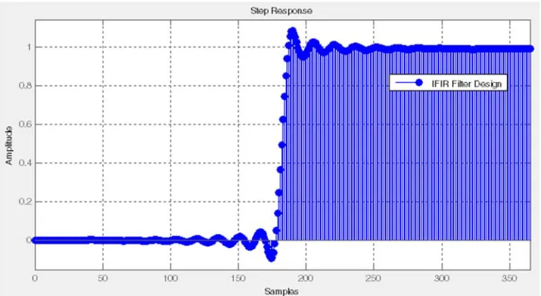
5.7. Step Response for IFIR Filter
Likewise, the screenshot of step response for IFIR lowpass filter is shown in Figure 8. The steady state condition is around 300 samples after analyzing the IFIR low pass filter design. It is very secure to superior performance of IFIR lowpass filter evaluation.
5.8. Magnitude and Phase Responses for IFIR Filter
The screenshot of magnitude and phase responses for IFIR lowpass filter is mentioned in Figure 9. The phase response for IFIR lowpass filter is -370.5396 radians respectively due to the increment of samples in filter analysis. These responses offer the reasonable results for IFIR lowpass filter design analysis for high data rate situation in satellite communication system.
Figure 9. Screenshot of Magnitude and Phase Responses for IFIR Filter.
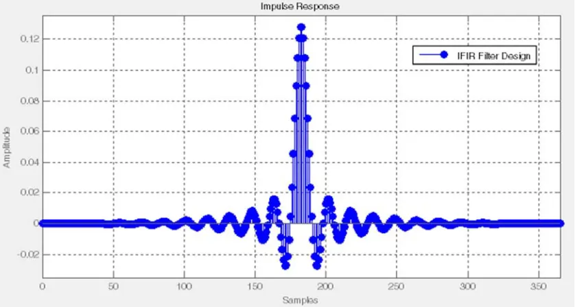
5.9. Impulse Response for IFIR Filter
The screenshot of impulse response for IFIR lowpass filter is shown in Figure 10. It is very expedient response for high data rate filter analysis.
Figure 10. Screenshot of Impulse Response for IFIR Filter.
6. Conclusion
A Digital IFIR filter is designed, simulated & implemented in MATLAB. The designed filter can be used in DSP based Costas loop demodulator for enhancing its frequency of operation & stability. Result shows that operating frequency of IFIR filter is more than 5 times of that of IIR filter and when it is used in demodulator then the system operating frequency increase by 3 times to that of corresponding IIR filter based demodulator. Hardware side also IFIR filter uses less multiplier. The designed IFIR filter is free from limit
cycle problem, hence highly stable in noisy input signal. The number of taps is less than conventional FIR filter and by using the symmetric property the hardware is reduced further. As the entire design is written in VHDL language, therefore can be targeted to hardware developments.
Acknowledgements
References
[1] Elbert, Bruce R., Introduction to Satellite Communication, 2d ed., Norwood, MA: Artech House, 1999.
[2] Elbert, Bruce R., the Satellite Communication Applications Handbook, Norwood, MA: Artech House, 1997.
[3] Freeman, Roger L., Telecommunications Transmission Handbook, 4th ed., New York: Wiley, 1998.
[4] Jasik, Harry, “Fundamentals of Antennas,” Antenna Engineering Handbook, 3d ed., ed. Richard C. Johnson, New York: McGraw-Hill, 1993, pp. 2–39.
[5] Flock, Warren L., Propagation Effects on Satellite Systems at Frequencies Below 10 GHz: A Handbook for Satellite Systems Design, NASA Reference Publication 1108(02), Washington, D. C.: National Aeronautics and Space Administration, 1987, pp. 3–12.
[6] Schmidt, W. G., “The Application of TDMA to the Intelsat IV Satellite Series,
[7] COMSAT Technical Review, Vol. 3, No. 2, Fall 1973, p. 257.
[8] Suyderhoud, H. G., Jankowski, J. A., and Ridings, R. P., “Results and Analysis of the Speech Predictive Encoding Communications System Field Trial,” COMSAT Technical Review, Vol. 4, No. 2, Fall 1974, p. 371.
[9] Larson, Lawrence E., ed., RF and Microwave Circuit Design for Wireless Communications, Norwood, MA: Artech House, 1997.
[10] Glisic, Savo, and Branka Vucetic, Spread Spectrum CDMA Systems for Wireless Communications, Norwood, MA Artech House, 1997.
[11] Balston, D. M., and R. C. V. Macario, eds., Cellular Radio Systems, Norwood, MA: Artech House, 1993.
[12] Juan Sebastián Galaz, “High Order RF Filters for Communications”, IWMF 2015 – 6th CNES/ESA International Workshop on Microwave Filters.
[13] Manning, R. M., “Real-Time Identification and Control of Satellite Signal Impairments – Solution and Application of the Stratonovich Equation: Part 1. Theoretical Development,” NASA TM- 2016-219114, 2016.
[14] Ashish Kumar Sahoo, Kaushik Basu, Ned Mohan,”Systematic Input Filter Design of Matrix Converter by Analytical Estimation of RMS Current Ripple”IEEE Transactions on Industrial Electronics, vol.62, issue.1, pp.132-143,2015.