Microprocessor-Based Protective Relays Applications in
Nigeria Power System Protections
J.O. Aibangbee
#1, S.O. Onohaebi
*2.
#Department of Electrical &Computer Engineering, Bells University of Technology, Ota, Nigeria *Department of Electrical / Electronic Engineering, University of Benin, Nigeria
Abstract-- Electric Utilities Company of Nigeria (EUCN) have traditionally used electromechanical (EMR) distance relays for the protection of transmission lines in the past, and many such relays are still in use in power systems today. In this paper, microprocessor-based protective relays (MPBRs) applications in the Nigeria power systems protection were investigated.
This paper evaluates the performance of a transmission line protection scheme using
Microprocessor-based protective and
Electromechanical relays using discrete components, for comparison in terms of engineering design, installations, maintenances costs, and applications flexibility.
Results shown that maintenance and design of protection schemes using EMR is expensive and time-consuming. MPBRs offer many advantages and benefits over EMR includes compactness, reliability, flexibility, number of installations components, maintenances costs, applications flexibility, are greatly reduced and improved monitoring and control functions. It reduces maintenance costs by providing self-test functions and high reliability, remote targets; metering data memory capabilities, fault location and status information to assist operations in restoration of electrical service. Fault location and event reports provide valuable information leading to improvement in the overall protection schemes. The overall scheme takes up less panel space, the design and wiring is simpler and less costly to implement. Installation and maintenance testing are greatly reduced.
Keywords: Power system, Microprocessor-based relays, electromechanical relays, engineering design, maintenances costs, protection schemes.
I. INTRODUCTION
Protective relays play a critical role in the operation of the electrical power system. Protective relays are designed to take action when abnormal conditions occur on the power system. These abnormal conditions may be short circuits, overload conditions, and loss of system synchronism. Protection schemes have typically been made up of discrete components such as overcurrent relays, distance relays, auxiliary relays, and reclosing relays. All of the devices must be wired together to have a complete, functional scheme, which means time and money in the design, development, and installation process.
Due to the number of components that make up these protection schemes, detailed installation tests, and routine maintenance programs can be performed to ensure that the schemes are functioning correctly. This requires a significant investment in time, money, and manpower. Increased growth in power systems both in size and complexity has brought about the need for fast, accurate and reliable protective schemes-to protect major equipment and to maintain
system stability. Microprocessor-based relays
(MPBRs) offer many advantages over schemes using discrete components. The overall scheme takes up less panel space. The number of components is greatly reduced. The design and wiring is simpler and less costly to implement. Installation and maintenance testing can be greatly reduced. MPBRs offer many advanced features and functions in addition to their basic protection functions, for instance, fault locating, event reporting, and self-checking. The added benefits of simple scheme design and improved reliability make them a very attractive option [1]. The relay implement more flexible protection schemes, reduce maintenance, and obtain more information to increase understanding of the power system, and improve the reliability of the protection system as a whole at a cost less than conventional electromechanical relays [2].
II. GENERALDESCRIPTIONS
A. Electromechanical Relays
Electric power utilities in Nigeria have traditionally used electromechanical (EMR) distance relays for the protection of transmission lines in the past, and many such relays are still in use in power systems today. These relays worked based on creating a mechanical force to operate the relay contacts in response to a fault situation. The mechanical force is established by the flow of a current that reflected the fault current through windings mounted in magnetic cores. Due to
the nature of its principle of operation,
impracticable. These relays have the following limitations;
Low speed of operation, single function
characteristic curve, and component failure leading to relay failure.
Excessive power consumption, Imposes high
burden on instrument transformers,
No fault data available except phase
indication.
Electromechanical relay is a hard wired relay. Its wiring is fixed, and the setting is manually performed. A calibrated adjustment called the time dial sets the spacing between the moving and stationary contacts; this varies the operating time of the relay from fast to slow.
B) Microprocessor-Based Relays
Microprocessor-based relays incorporated analog-to-digital converter (ADC) to sample the analog signals incoming from instrument transformers, and used microprocessor to define the logic of the relay. These relays feature advanced programmable functions
which maximize flexibility and monitoring
capabilities, and offer a wide choice of characteristics curves. It replaces most of the electronic circuitry;
thereby maximizing integration of advanced
protection functions, fault location, event recording, control and monitoring, alarm and annunciation, metering and communication into a single device. The main advantages of microprocessor relays over
electromechanical relays are their reliability,
functional flexibility, self-checking and
self-adaptability. Microprocessor relays are able to implement more complex functions, be more accurate and be immune from physical environment effects [3]. It reduces maintenance costs by providing self-test functions and high reliability, provides remote targets, metering data memory capabilities, fault location and status information to assist operations in restoration of electrical service, in addition to protection functions.
Additional features commonly available on
microprocessor-based relays are sequence of Event recorders (SER), Disturbance Recorders (DR), measurement functions and power quality monitoring
(PQM). The relay also uses sophisticated
communication for signaling other remote relays [4].
III SYSTEM EVALUATION
A) Space Requirements of Hardware
A typical three-zone step time distance scheme
consists of instantaneous tripping elements, two levels of time-delayed tripping elements for phase faults andan instantaneous tripping element, and time
overcurrent element for ground faults. For
this example, we shall assume that the step time distance scheme uses phase distance and directional ground overcurrent elements. Phase faults are detected using three zones of phase distance relays. Ground faults are detected using a directional ground overcurrent relay which includes a time-overcurrent element and an instantaneous overcurrent element.
The protection scheme also includes a single-shot recloser for automatic line restoration after a fault has been cleared.
The electromechanical relay scheme uses three-phase distance relays. These relays may cover all fault types on a per-zone basis or all three zones on a faulted phase pair basis. This depends upon the manufacturer of the distance relays. However, in either case, three distance relays are required. A timer is also required for the time-delayed backup elements. Typically, the time delay is provided from separate timers, so if one timer fails, the entire step time distance scheme is not lost. A single directional ground overcurrent relay shall be used for ground fault detection. A single-shot reclosing relay shall also be provided for restoring the line. A non-directional overcurrent relay shall be used to supervise the distance relays.
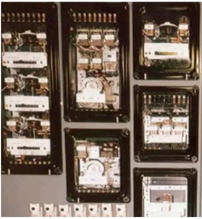
A Combination of electromechanical and
microprocessor-based relays scheme panel is shown in Figure 1(a) and (b). The electromechanical scheme requires nearly all of the space contained in a 213cm by 48cm panel [3]. The microprocessor-based scheme consist of a multifunction relay that provides three zones of step time distance protection, three levels of instantaneous or definite time directional ground overcurrent protection, a directional ground time-overcurrent function, and three-shot recloser [9]. The microprocessor-based scheme also includes a single-zone microprocessor-based relay as a backup in case of failure of the primary multi-zone relay. The space requirement for the microprocessor-based relay scheme is much less than the electromechanical relay scheme [5, 6].
Figure 1 (a): Typical Electromechanical Relay Scheme Panel
Figure 1 (b): Typical Microprocessor-Based Relay Scheme Panel
Layout
Given that the cost of all the relays for the electromechanical scheme is 1 per unit (p.u.), the cost of the microprocessor-based relay scheme is 0.35 P.u.
(B) Circuits Design
The ac and dc circuits for the electromechanical scheme are more complex than the microprocessor-based relay scheme.
Figure 2(a) shows a typical ac schematic, and Figure 2(b) shows a typical dc schematic for the electromechanical relays scheme. Each discrete relay must be wired to other discrete relays to develop the
required protection scheme. The design and
installation costs can be quite high due to the number of connection points and the relative complexity of the overall scheme.
Figure 2: (a) Typical Electromechanical Relay AC Circuit
Figure 2: (b) Typical Electromechanical Relay DC Circuit Table 1 shows IEEE device numbers and their functions used in the text,
Table 1: IEEE Standard Device Numbers Device
Numbers
RELAYS FUNCTIONS
11 Multifunction Device
21 Distance Relays
50 Instantaneous Overcurrent
Relays
51 AC Time Overcurrent Relays
52 AC Circuit Breaker
62 Time Delay stopping or opening
Relays
67 AC Directional Relays
79 AC Reclosing Relays
TC Trip Coil
Z Zone(s)
Figures 3(a) and (b); shows the AC and DC circuits for a MPBR schemes. With the redundant relay used for backup protection, the number of connections and complexity is very low. Therefore, the design and installation costs are reduced significantly.
Figure 3: a) Typical microprocessor-based relay AC Circuit
Figure 3: b) Typical microprocessor-based relay DC Circuit
Given that the cost of design and installation of the electromechanical relay scheme is 1 p.u., the cost of design and installation of the microprocessor-based relay scheme is approximately 0.5p.u.
are performed to ensure that the relays are functioning within established specifications. A scheme designed with electromechanical relays requires a large number of tests during installation to ensure that the overall scheme is functioning properly. Each discrete relay must be tested and calibrated.
For the step time distance scheme example, at least seven discrete relays must be tested. The testing of each relay requires that the relay be connected to the test equipment, the various setting adjustments are made, and the relay is tested per an established test routine. If the relay test results are outside established guidelines, the relay must be calibrated. The calibration routine can be very time-consuming. After each relay has been tested, the scheme must be "trip-checked" to ensure that all of the wiring and trip circuits are correct. Many times, trip-checking an electromechanical scheme is a simple matter of manually closing an output contact. Therefore, the trip-checks can be very simple. However, due to the many discrete devices used in the scheme, the trip-checks can be very time-consuming and, in case of an incorrect design or wiring error, require many hours of trouble shooting when searching for problems.
A microprocessor-based relay scheme is very simple to test and verify .A microprocessor-based relay operates using software programming. Once the relay has been fully tested, the software that defines the operating characteristics of the relay has been verified. Therefore, it is not required to fully test each relay given that the relays are of the same type and software version.
The installation tests for a microprocessor-based relay should be designed to verify that the relay settings have been entered correctly. The test series should be designed to check the relay pick-up at critical points. For example, the distance element should be tested at the angle of maximum torque and: t30 degrees off the angle of maximum torque. These test points verify the distance element settings. Overcurrent elements should also be tested using a very simple test routine. Trip checks using a microprocessor-based relay are very simple due to the fact that there are fewer contacts to check and less wiring to verify .In many cases, a software command may be used to close specific output contacts. Using a software command to close relay outputs is simpler than connecting voltage and current test sources to the relay to perform fault simulations.
(D) Periodic Testing
Periodic tests are performed on
electromechanical relays to verify that they are operating within specified guidelines. These tests may be at one to three year intervals for distance relays based upon the specific utility's practice. The periodic tests performed on an electromechanical relay are very similar to those done during the installation process. The relays must be thoroughly tested to verify that all
of the internal components are operating within specified tolerances. Periodic tests also confirm that all contacts and external circuits are functioning properly. Periodic testing of electromechanically relays is performed to assure that the calibration of the relays remains within allowable limits and to verify that the capability of the protection system to trip the breaker remains intact. Electromechanical relays are subject to a variety of environmental factors that can affect their operational characteristics over time. Electromechanical relays are prone to failures due to environmental factors. That may not affect digital relays. Factors, such as aging, that change a component’s characteristic or value, wear and binding of bearings due to temperature variations, dirt on discs and cups that affects their operating time, oxides that form on contacts to increase their resistance and prevent circuit continuity, are all potential defects that will alter a relay’s performance. As a result of these failure possibilities, and since most of these defects cannot be detected with the relay in service, many test procedures call for removing the relay from its case for inspection, and possibly dismantling part of the device for cleaning and adjustment [7]. Microprocessor-based relays perform routine self-checks to ensure that the critical circuitry in the relay is functioning properly. Microprocessor-based relays continuously run the same software routines. Therefore, if the relay is functioning properly, the relay algorithms shall operate correctly. Periodic maintenance in a microprocessor-based relay consists of verifying that the inputs, outputs, and data acquisition system are functioning properly. If the relay is properly measuring the analog currents and voltages and the self-check status show that the relay is healthy, the relay shall function correctly. The only other checks necessary are to verify that the output contacts and logic inputs are operating correctly [8]. Microprocessor-based relay includes sufficient self-checking and a common data acquisition system is used for relaying as well as metering, periodic maintenance can be significantly reduced. Many utilities have extended the periodic maintenance cycle of microprocessor-based relays from one and one-half to three times that used on electromechanical relays.
(E) Microprocessor-Based Protective Relays Features
Microprocessor-based relays offer many other features that electromechanical relays do not offer such as fault locating, event reporting, advanced metering functions and control capability.
i. Fault Location
every breaker where a microprocessor-based relay is installed. The event data is an invaluable tool in evaluating relay and system performance. The microprocessor-based relay also provides analog metering quantities such as three-phase currents, voltages, megawatts, and megavars. The data can also be directly interfaced digitally to the SCADA RTU. The fault locator can be send to the system control center for dispatching a patrol crew.
Fault locating has become a standard feature in all microprocessor-based relays. The fault locating information reduces patrol time on permanently faulted lines. The fault locating information can also be used to evaluate problem areas on transmission lines.
Identifying the location of fault is an important process for promoting higher reliability of electric power systems. Such knowledge is especially important for faults on lines because lines extend over large geographical area. Knowledge of the location of a permanent fault allows the utilities to promptly dispatch personnel to the scene to make necessary repairs [8]. The sooner the personnel arrive at the scene the faster the service can be restored. Experience has shown that a significant portion of outage times are caused because of the time required in locating the failure. In addition finding the location of a transient fault can result in the identification and replacement of damaged power system facilities. Damaged such as cracked insulators and conductors with burnt stands have often been found at the scene of a transient faults. Identification of such damage allows for the development of a replacement plan that minimized the impact on customer service and acts to prevent a likely permanent failure and customer outages in the future [9, 12].
Modern microprocessor-based relays include the capability for calculating and displaying the distance to the fault. The calculated fault location is displayed in terms of kilometers to the fault from the associated relay location. To derive this value some additional data must be provided to the relay with regard to the line impedance and the line length. The distance to the fault information in usually displayed on the relay and is sent to the communication port of the relay, from which it can be transmitted to interested personnel such as system operators and protection engineers. In existing installation using electromechanical relays, EUCN relied to a large extent on calls from the public or manual patrols of the line to find the location of a fault. In cases for which fault recorder data were available, off-line comparisons of fault data and fault study results were been conducted to develop an estimate of the fault location. On account of the limited availability of fault recorder data, such analysis could only be conducted for a relatively small number of faults. It often took considerable time to retrieve information from older types of fault
recorders and time is also required to perform the related analysis.
ii. Event Reports:
The event record provides data on the internal relay element operation and the currents and voltage waveforms at the time of operation. This is similar to having a fault recorder on every breaker where a microprocessor-based relay is installed. The event data is an invaluable tool in evaluating relay and system performance. The ability of microprocessor – based relays to record and display event reports has provided protection engineers powerful tools for analyzing the nature of power system disturbance and the related performance of protection and interrupting devices. For electromechanical relays, engineers had to rely on information received from fault and sequence of event recorders to analyze system disturbances. On the account of the relatively high cost of such devices they are usually installed only at the vital high-voltage stations. With the application of microprocessor- based relays the same types of information is available at every location where such device are applied. Event reports are stored record of what the relay saw and how it responded during a system fault or other type of event. The event reports contain date, time, current, relay elements, optoisolated input, and output contact information.
Microprocessor-based relays also provide analog metering quantities such as three-phase currents, voltages, megawatts, and mega-vars. In many cases, analog transducers are not required. The data can also be directly interfaced digitally to the SCADA remote terminal unit (RTU). You can also send the fault locator information to the system control center for dispatching a patrol crew [10, 11].
IV. RELAYS APPLICATIONS
Microprocessor-based relays are used in virtually
any application in which electromechanical relays are used. This section presents many of those applications.a) Replacement of Electromechanical Relay
As electromechanical relays fail or become
maintenance intensive, it can be cost justified to replace them. Microprocessor-based relays are perfect for replacing existing protection systems. The microprocessor-based relay uses much less panel space than the existing electromechanical relays. The schemes and operating principles are nearly identical. The wiring is simplified and can be easily modified to accommodate the new relay. The replacement cost is also very low with respect to replacing all or, in some cases, even one electromechanical relay.
at one end are failing, but the other terminal relays are still good.
b) New Installations
When building new substations or transmission lines, it is very easy to justify microprocessor-based relays. They are very cost-effective. They can be integrated into virtually any protection scheme or philosophy. Reducing the panel wiring and space requirement can also result is significant cost savings when building new substations. In many cases, when new transmission lines are built into existing substations, the panel board space is very limited. Again, since microprocessor-based relays provide full scheme protection using very little space, they are perfect for this application.
c) Communications-Aided Schemes
Many microprocessor-based relays include
communications scheme logic. In most cases, the relays include all of the required logic to operate in a particular communications-aided scheme. This saves design and materials cost since external auxiliary relays are not required for the scheme operation. The microprocessor-based relay also includes much of the logic that would be provided in the communications equipment. Using the relay's internal logic can reduce the cost of the communications equipment since extra modules may not be required.
The relay also offers selection of the different communications-aided tripping schemes. This means that you can standardize on one relay for all applications.
d) System Wide Application
Microprocessor-based relays offer programmable logic. The programmable logic allows the user to define the operation of the relay and invent unique protection schemes. The relays also offer a large variety of protection elements and schemes. The flexibility offered in these relays allows application at many voltage levels. In many cases, utilities have standardized on a single relay for all voltage applications from 33kV to 330kV.
e) Power System Analysis
Most microprocessor-based relays record the system conditions when protective elements operate or when user-defined conditions occur. The event recording tool is invaluable in power system and relay performance analysis. The event data can be used to evaluate the relay performance. Reviewing the event data is a valuable maintenance tool. The event report shows the ac and dc signals the relay measures during the disturbance and also shows when the relay closes the circuit breaker trip contact. Analyzing the event data is more useful and accurate than simulated tests because the relay is responding to an actual system fault. Therefore, the true relay performance can be
better evaluated. The event report can also show problems in control inputs and outputs. Analyzing the event reports can also provide valuable information leading to improvement in the overall protection scheme.
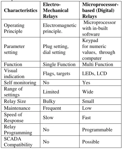
Table 2: Comparison of Electromechanical and Microprocessor-based Protection Schemes
Characteristics
Electro- Mechanical Relays
Microprocessor-based (Digital) Relays
Operating Principle
Electromagnetic principle.
Microprocessor with in-built software
Parameter setting
Plug setting, dial setting
Keypad for numeric values, through computer
Function Single Function Multi Function
Visual
indication Flags, targets LEDs, LCD
Self monitoring No Yes
Range of
settings Limited Wide
Relay Size Bulky Small
Maintenance Frequent Low
Speed of
Response Slow Fast
Relay
Programming No Programmable
SCADA
Compatibility No Possible
V CONCLUSION
version Microprocessor-based relays offer
many
advantages
and
benefits
over
electromechanical relays, these includes:
Microprocessor
relays
have
Communications
capabilities,
sequence-of-events recording, fault
reporting, rate-of-change frequency,
and metering functions, all in an
integrated system.
Have settings that are software-based
and do not drift with time, ambient
temperature, supply voltage changes,
or aging.
Reduction
in
installations
and
maintenances costs
Application flexibility
Improved
monitoring
and
control
functions.
It offers advanced features such as fault
locating, event reporting, self-checking,
etc.
The use of microprocessor-based relays is
therefore recommended. many utilities are
taking advantage of the new features and
innovations offered in these relays. new
developments in microprocessor-based relays
offer added benefits by further reducing costs
by improving the relay functions and features.
REFERENCES
[1] John J. Kumm, Mark S. Weber, E.O. Schweitzer, III, Daqing Hou,
"Philosophies for Testing Protective Relays," 48th Annual Georgia Tech Protective Relaying Conference, Atlanta, Georgia, May 4-6, 1994.
[2] Lewis J. Blackburn and Thomas J.Domin “Protective Relaying Principles and Applications”, third edition, 2007. [3] Sachdev, M. S. “Advanced microprocessor Based Protection
and communication”, IEEE Tutorial course. 1997. [4] Brad. Hendenson, “Protection Relay setting management in
the modern
world; cigre conference 2008
[5] John J. Kumm, Edmund 0. Schweitzer, III, Daqing Hou, "Assessing the Effectiveness of Self-Tests and Other Monitoring Means in Protective Relays," PEA Relay Committee Spring Meeting, Matamoras, Pennsylvania, May 25-26, 1995.
[6] Stanley H. Horowitz and A. G. Phadke “Power System Relaying” Third edition, England RSP Ltd, 2008.
[7] Sachdev, M. S. “Advanced microprocessor BasedProtection and communication”, IEEE Tutorial course.1997.
[8] Mohindar S.and Sachdev V. “Understanding Microprocessor-based Technology applied to relaying,” Power System Relaying Committee 2004.
[9] Jeff Roberts, Edmund 0. Schweitzer, III, "Analysis of Event Reports," 16th Annual Western Protective Relay Conference, Spokane, Washington, October 24-26, 1999.
[10] Zejlan Chan “Advanced Microprocessor-Based Intelligent Relay for Multifunctional Protection system” November 1995
[11] Stanley E. Zocholl, Armando Guzman, Daqing Hou. “Transformer modeling as applied to differential protection”, Schweitzer Engineering Laboratories, Inc. Pullman, Washington, USA. 2007.
[12] Guzman A., S. Zocholl, G. Benmouyal, and H. J Altuve,