Modeling of PV Interconnected Distribution System using
Simulink
Pooja A. Bhonge*1, Kawita D. Thakur2
*1PG Scholar, Department of Electrical Engineering, GCOE, Amravati, Maharashtra, India 2Assistant Professor Department of electrical engineering, GCOE, Amravati, Maharashtra, India
ABSTRACT
Distribution system is a final link between power system and consumer. The distribution system are of three types: ring main, radial, interconnected. In Radial distribution system power is received at the utility bus at supply voltage level by a single distribution substation. In this paper, modeling of benchmarked example of unbalanced radial distribution system is presented. The distribution system fed from single phase photovoltaic in phase a as well as Three phase source to supply the load demand. The simulink model is built in MATLAB software using simpower system toolbox.
Keywords : Single Phase Photovoltaic, Induction Machine, Distribution System, Maximum Power Point Tracking.
I.
INTRODUCTION
In today’s era solar energy is one of the most important available resources of energy. It is available in abundant amount and it is distributed all over the world. Photovoltaic (PV) has shared a maximum amount of renewable energy penetration in microgrids where the PV power supplies electrical loads for local communities. Also induction machine loads are more dominant in distribution systems. The unbalanced radial distribution system consists of single phase PV, Power Factor correction Capacitor (PFC), load and induction machine. Since PV system is single phase it is connected to phase a and all other lines are three phase. Thus, the PV array supplies the single phase ac power into the grid. The electric power generated using PV changes continuously with weather conditions such as temperature and irradiance. This connection of PV system to grid introduces the unbalance in the distribution system.
irradiation and temperature changes. The output power of a PV cell becomes a function of maximum power point corresponding to the particular value of operating voltage indeed a non linear function of the operating voltage. In order to operate at the MPP, an energy power converter must be connected at the output of a PV array, such converter forces the output voltage of the PV array is equal to the optimal value.
The main objective of this paper is to model, analyze and simulate an unbalanced distribution system with both complex loads such as induction machine (IM) and renewable such as inverter interfaced PVs. This model can be used in micro grid studies such as power quality, harmonic mitigation or resonance issues. The detailed PV model consists of a single phase synchronizing phase locked loop (PLL), proportional resonance (PR) controller, and maximum power point tracking unit.
The remaining part of the paper is described as follows. In Section 2 the system description is described. PV control composed of PR controller and MPPT and PLL are described in Section 3. In section 4 MATLAB simulink model and results are given. Section 5 is the conclusion.
II.
SYSTEM DESCRIPTION
The study system which is used in this paper is an unbalanced radial distribution system. It consists of a three phase induction machine, a power factor correction (PFC) capacitor, a single phase PV and load. The single line diagram of the study system is as shown in figure 1.
Figure 1. Single phase PV connected to distribution grid
The single phase PV is installed in phase a of three phase system. All the elements of the system are connected at point of common coupling. The PV system generates DC Power which cannot be fed directly to the distribution grid. It necessitates converting it into AC power which is then fed to distribution grid. The converter converts the DC power to AC power. The conversion of DC to AC is as shown in fig. 2 which shows the basic configuration of single phase PV system.
Figure 2. PV energy conversion system
Figure 2 shows that the DC power generated by PV array is converted into AC using single phase IGBT inverter. The AC side of the inverter bridge is connected to the filter circuit. Here the combination of series inductor with shunt capacitor is used as filter circuit. The LCL filter removes the harmonics on AC side of converter. This AC power is boosted to the grid voltage Vg by using step up transformer [1].
III.
CONTROL STRATEGY
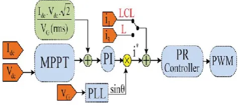
Figure 3. Control structure.
The output of the PR controller is sent to the pulse width modulation generator block to generate the pulses for the PV inverter. A phase locked loop is used to synchronize the PV reference current with the AC grid. The detailed PV control structure is explained with MPPT control algorithm, PR controller, and PLL [10].
MAXIMUM POWER POINT TRACKER
Maximum power point tracking technique increases the efficiency of the solar panel. A typical solar panel converts only 30 to 40 percent of the incident solar irradiation into electrical energy. According to maximum power transfer theorem, the power output of a circuit is maximum when the source impedance is equal to the load impedance. In the source side a buck-boost converter is connected to a solar panel in order to increase the output voltage. By changing the duty cycle of the boost converter appropriately the source impedance is become equal to that of the load impedance. Different techniques have been used for tracking the maximum power point of PV curve. Among these methods, the Perturb & Observe (P&O) and Incremental Conductance methods (INC) are widely used methods.
In this paper incremental conductance algorithm has been chosen. This algorithm has advantages compared to perturb & observe as it can determine MPP more efficiently and accurately. When the MPPT has reached the MPP, where perturb and observe
condition can track rapidly by incremental conductance algorithm with higher accuracy than perturb & observe. One disadvantage of this algorithm is the increased complexities as compared with perturb & observe. This will increases the computational time and slows down the sampling frequency of the array voltage and current.
In incremental conductance algorithm, the output current and voltage of the photovoltaic panel are used to calculate the conductance and incremental conductance. Then the conductance ( Idc/Vdc) are compared with the incremental conductance (dIdc/dVdc) to decide whether to increase or decrease the PV current in order to reach the maximum power point. The flowchart of incremental conductance algorithm is as shown in figure 4.
Let us consider,
P=V.I
At the maximum power point, the derivative of P with respect to V should be zero.
( )
Figure 4. Incremental conductance MPPT Flowchart.
PHASE LOCK LOOP
The PLL is used to provide a unity power factor operation. The PLL synchronizes the inverter output current with the grid voltage and results in a clean sinusoidal current reference. The PI controller parameters of the PLL structure are calculated in such a way that the settling time and the damping operation. The PI controller parameters of the PLL structure are calculated in such a way that the settling time and the damping factor of this PLL structure can be set directly. The PLL structure is also used for grid voltage monitoring in order to get the amplitude and the frequency values of the grid voltage.
PROPORTIONAL RESONANCE (PR) CONTROLLER The PR controller is used to track a sinusoidal signal reference. The dynamics of PR controller is expressed as
( ( ) ) ( )
The PR controller provides an infinite gain in a very narrow band width that is at the resonance frequency. Thus, steady-state error is eliminated at the resonance frequency resulting PR has reached to very high gain around the resonance frequency. When the gain is maximum at the resonance frequency, the steady state error reaches zero. Therefore PR controller is used to track designed frequency signals. So that the PR controller for single phase PV has been designed to reduce the higher order frequencies like 3rd, 5th, 7th and 9th. The Proportional resonance controller controls the grid side AC current. To achieve this objective, the error of the reference PV current and measured PV current will be used as the input for the PR controller. The magnitude of the reference current generated from the output of the MPPT block will be synchronized with the grid voltage before sending to the PR controller. The synchronization steps will be conducted in a single phase PLL block. The output generated from the PR controller is the voltage reference which will be directly given to the pulse width modulation (PWM) generation unit [8].
IV.
MATLAB SIMULATION AND RESULTS
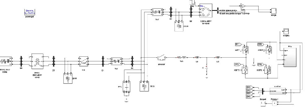
coupling. A three phase induction machine is connected as load.
In this model response for induction machine are obtained for dynamic event of step change in load torque of induction machine. The simulation results
are as shown in fig. 6. At t=4 s, a step change of torque from 28 N.M. to 23 N.M. are applied to induction machine and results are obtained for electromagnetic torque and rotor speed as shown in figure 6.
Figure 5. Simulation model
Figure 6. Simulation results
V.
CONCLUSION
This paper presents a simulation based model of an unbalanced radial distribution system with single
array is presented. The effect of the dynamic event such as step change in load torque of induction machine are investigated. It shows that by changing torque rotor speed of machine gets change. Reduction in torque increases the rotor speed of induction machine.
VI.
REFERENCES
[1]. Zhixin Miao, Lakshan Piyasinghe, Javad Khazaei, and Lingling Fan," Dynamic Phasor-Based Modeling of Unbalanced Radial Distribution Systems", IEEE transactions on power systems, vol. 30, no. 6, November 2015. [2]. D. Zammit, C. Spiteri Staines, M. Apap,
"Comparison between PI and PR Current Controllers in Grid Connected PV Inverters", International Journal of Electrical, Computer, Energetic, Electronic and Communication Engineering Vol. 8, No. 2, 2014.
Advancements in Research & Technology, Volume 2, Issue 5, May-2013 358 ISSN 2278-7763.
[4]. Ahmed K. Abdelsalam,, Ahmed M. Massoud, Shehab Ahmed, and Prasad N. Enjeti, "High-Performance Adaptive Perturb and Observe MPPT Technique for Photovoltaic- Based Microgrids", IEEE Transactions on power electronics, vol. 26, no. 4, April 2011.
[5]. Atiqah Hamizah Mohd Nordin, Ahmad Maliki Omar," Modeling and Simulation of Photovoltaic (PV) Array and maximum Power Point Tracker (MPPT) for Grid-Connected PV System", 3rd International Symposium & Exhibition in Sustainable Energy & Environment, 1-3 June 2011, Melaka, Malaysia. [6]. A. Safari and S. Mekhilef, Kuala Lumpur,
"Incremental Conductance MPPT Method for PV Systems", IEEE CCECE 2011-000346.
[7]. Michael E. Ropp, Sigifredo Gonzalez, " Development of a MATLAB/Simulink Model of a Single-Phase Grid-Connected Photovoltaic System", IEEE Transactions on energy conversion, 0885-8969/$25.00 © 2009 IEEE. [8]. Hanju Cha, Trung-Kien Vu and Jae-Eon Kim,"
Design and Control of Proportional-Resonant Controller Based Photovoltaic Power Conditioning System", 978-1-4244-2893-9/09/$25.00 ©2009 IEEE.
[9]. I. H. Altas, A.M. Sharaf,"A Photovoltaic Array Simulation Model for Matlab-Simulink GUI Environment", 1-4244-0632-3/07/$20.00 ©2007 IEEE.
[10]. Mihai Ciobotaru, Remus Teodorescu & Frede