© 2017 IJSRST | Volume 3 | Issue 7 | Print ISSN: 2395-6011 | Online ISSN: 2395-602X Themed Section: Science and Technology
Modeling of Ceramic Bonded Grinding Wheel Structures
1
J.
Rupesh Kumar,
2Dr. R. Ramachandra
1
M.Tech, Dept. of Mechanical Engineering, SKD Engineering College, Gooty, Andhra Pradesh, India
2
Supervisor, Principal & Professor, Dept. of Mechanical Engineering, SKD Engineering College, Gooty, Andhra Pradesh, India
ABSTRACT
The proper choice of a grinding tool is essential for a productive grinding process and a high quality of the resulting work piece surface. Hence, the grinding wheel structure consisting of abrasive grain material, bonding material and pores has to be composed wisely. We present a new approach for mathematically modelling such grinding wheel structures with the objective of predicting the volumetric composition of the grinding wheel components such that grinding requirements can be met without using trial and error methods. For the model, we focus on a small element of a grinding wheel, such as a cube, which we call volumetric structure element (VSE). In this project, we concentrate on several aspects of the modeling procedure, namely the initial grain arrangement, a collision-free grain rotation and translation algorithm to obtain required grain volume fractions in a VSE, the tetrahedral mesh generation for a whole VSE and the modeling of ceramic bond.
Keywords: Mathematical Grinding Wheel Modeling, Granular Structures, Ceramic Bond, CBN
I.
INTRODUCTION
Abrasive machining is a grinding process for removing material from a work piece by using expendable abrasive mineral materials in a wheel, stone, belt, paste, sheet, compound, slurry, or other abrasive products. Abrasives are mineral materials from a selected group of very hard materials used to shape, finish, or polish other materials, while a wheel is a circular device that is capable of rotating on its axis thereby facilitating movement. Thus, a grinding wheel is an expendable wheel which carries abrasive particles on its periphery used for grinding a workpiece. They are composed of thousands of small sharp and very hard natural or synthetic abrasive grains bonded together in a matrix to form a wheel. Each abrasive grain is a cutting edge and as the grain passes over the work piece, it cuts a small chip, leaving a smooth, geometrical/dimensional accurate surface.
As the abrasive grain becomes dull, it breaks away from the bonding material exposing new sharp grains. The grinding of crankshaft and other precision components is only made possible by using the grinding wheels and without grinding wheel the achievement of high
precision surface finish to very high tolerance would not have been possible. The shaping and dressing of hard cutting tools such as high speed steel, carbide, diamond cutting and cubic boron nitride (CBN) are only possible with application of grinding using grinding wheels. Abrasive machining as a grinding process predates civilization when sandstone was the only bonded abrasive used for most of the grinding work. The art of grinding dates back many centuries, since man first discovered that he could brighten up and sharpen his tools by rubbing them against certain stones or by plunging them into sand several times. The emery stone appeared when man found that the softer sand stone did not work well on the newly discovered harder materials.
The principles of grinding involve the use of abrasive tool whose cutting elements are grains of abrasive materials. These grains are of high hardness (2200 to 3100 kN/mm2) and have a high heat resistance. Grinding is mainly a machining process employed for the attainment of tight tolerance (two dimension tolerance and compatible geometric tolerance), reduced roughness values (Ra from 0.2 to 1.6 μm) and due to the great number of variables involved, grinding is one of the most complex machining processes. Grinding with modern abrasive is a metal cutting process like other conventional metal cutting tools except that the grinding wheel consists of thousands of tiny cutting edges instead of the few large edges possessed by other rotary cutters, such as the milling cutter. The temperature reached by the tip of the abrasive particles when cutting is extremely high and higher than the melting point of steel which is 1,5000C. However, no melting of grains occurs due to brief time of contact, which is often less than 100 x 10-6sec. The different depths of cut on work piece deformation had been discovered to affect the hardness of the abrasive wheel. However, the most generally recognized characteristic wheel hardness is the ability of the wheel to retain dulled abrasive grains. The duller the retained grains, the harder the wheel.
Grinding wheels are complex high precision tools applied to a great variety of work piece materials. They are used for finishing operations to ensure a high surface quality as well as for high material removal processes. The major components are abrasive grain material, bonding material and pores, where grain diameters vary between a submicrometer range and about 500m. The main conventional abrasive grain materials are corundum and silicon carbide, whereas cubic boron nitride (CBN) and diamond with a higher degree of hardness are the so-called super abrasive materials. The main advantages of CBN in comparison with diamond are its thermal stability and the applicability to grinding ferrous materials. Hence, we concentrate on CBN as grain material. The grains are bonded using vitrified (ceramic), resin (polymer) or metallic bonding systems. Most previous works for modeling and simulation of grinding processes focus on the grinding wheel topography, i.e., on the surface of the grinding wheel. The modelled topography is often used as an input parameter for the development of force models or for the
model in which they distribute grains with a CBN-like shape randomly on the grinding wheel surface. In the simulation, the grains can be intersected during the cutting process to reset the topography. Hence, the composition is essential for the grinding result, i.e., for the nal work piece surface quality. Since determining a suitable composition is a process nearly exclusively based on experience, it can be very expensive and time-consuming. We develop an approach for mathematically modeling the grinding wheel structure with the objective of predicting the volumetric composition of the grinding wheel components such that grinding requirements can be met without using trial and error methods.
GRINDING
Grind means to abrade, to wear away by friction, or to sharpen. In manufacturing it refers to the removal of metal by a rotating abrasive wheel. Wheel action is similar to a milling cutter. The cutting wheel is composed of many small grains bonded together, each one acting as a miniature cutting point.
TYPES OF GRINDERS
Cylindrical grinders
This machine is used primarily for grinding cylindrical surfaces, although tapered and simple format surfaces may also be ground. They may be further classified according to the method of supporting the work .Diagrams illustrating the essential difference in supporting the work between centers and centerless grinding. In the centerless type the work is supported by the work rest the regulating wheel, and the grinding whell itself. Both types use plain grinding wheels with the grinding face as the outside diameter.
not necessary to traverse the work. This is known as plunge cut grinding. The grinding speed of the wheel is terms of surface feet per minute that is,
VC=πDcxN
Where
Vc=Cutting or grinding speed(m/min)
Dc=Diameter of grinding wheel(m)
N=Revolutions of the wheel per minute (rpm)
Centerless grinders
Centerless grinders are designed so that they support and feed the the work by using two wheels and the large wheel is the grinding wheel and the smaller one the pressure or regulating wheel. The regulating wheel is a rubber-bonded abrasive having the frictional characteristics torotate the work at is own rotational speed.The speed of this wheel, which may be controlled, varies from 50 to200 ft/min(0.25-1.02 m/s). Both wheels are rotating the same direction. The rest assists in supporting the work while it is being ground, being extended on both sides to direct the work travel to and from the wheels. The axial movement of the work past the grinding wheel is obtained by tilting the wheel at a slight angle from horizontal. An angular adjustment of 00 to 100 is provided in the machine for this purpose. The actual feed can be calculated by this formula.
F=πdNsinα
F=Feed (mm/min)
N=rpms
d=Diameter of regulating wheel(mm) α=Angle inclination ofregulating wheel
Internal grinders
Internal grinding is used to grind the internal diameter of the work piece. Tapered holes can be ground with the use of internal grinders that can swivel on the horizontal. Center less grinding is when the work piece is supported by a blade instead of by centers or chucks. Two wheels are used.
Surface grinding
Grinding flat or plane surfaces is known assurfaces grinding. Two general types of machines have been developed for this purpose; those of the planer type with a reciprocating table and those having a rotating worktable. Each machine has the possible variation of a horizontal or vertical positioned grinding wheel spindle.
Tool and cutter grinder
In grinding tools by hand a bench or pedastal type of grinderis used. The tool is hand held and moved across the face of the wheel continually to avoid excessive grinding in one spot. For sharpening miscellananeus cutters a universal type grinder is used.
Two types of abrasives are used in grinding wheels: natural and manufactured. Except for diamonds, manufactured abrasives have almost entirely replaced natural abrasive materials. Even natural diamonds have been replaced in some instances by synthetic diamonds.
The manufactured abrasives most commonly used in grinding wheels are aluminum oxide, silicon carbide, cubic boron nitride, and diamond.
Aluminum oxide:
Refining bauxite ore in an electric furnace makes aluminum oxide. The bauxite ore is heated to eliminate moisture, then mixed with coke and iron to form a furnace charge. The mixture is then fused and cooled. The fused mixture resembles a rocklike mass. It is washed, crushed and screened to separate the various grain sizes.
Aluminum oxide wheels are manufactured with abrasives of different degrees of purity to give them certain characteristics for different grinding operations and applications. The color and toughness of the wheel are influenced by the degree of purity.
General-purpose aluminum oxide wheels, usually gray and 95 percent pure are the most popular abrasives used. They are used for grinding most steels and other ferrous alloys. They are used for grinding most steels and other ferrous alloys. White aluminum oxide wheels are nearly pure and are very friable (able to break away from the material easily.) They are used for grinding high-strength, heat-sensitive steels.
Silicon carbide:
Silicon carbide grinding wheels are made by mixing pure white quartz, petroleum coke and small amounts of sawdust and salt, and then by firing the mixture in an electric furnace. The process is called synthesizing the coke and sand. As in the making of aluminum oxide abrasive, the resulting crystalline mass is crushed and graded by particle size.
Silicon carbide wheels are harder and more brittle than aluminum oxide wheels. There are two principal types of silicon carbide wheels: black and green. Black wheels are used for grinding cast irons, non-ferrous metals like copper, brass, aluminum, and magnesium, and nonmetallics such as ceramics and gemstones. Green silicon carbide wheels are more friable than the black wheels and used for tool and cutter grinding of cemented carbide.
Cubic boron nitride (CBN):
Cubic boron nitride is an extremely hard, sharp and cool cutting abrasive. It is one of the newest manufactured abrasives and 2.5 times harder than aluminum oxide. It can withstand temperatures up to 2,500°F. CBN is produced by high-temperature, high-pressure processes similar to those used to produce manufactured diamond and is nearly as hard as diamond.
CBN is used for grinding super-hard, high-speed steels, tool and die steels, hardened cast irons, and stainless steels. Two types of cubic boron nitride wheels are used in industry today. One type is metal-coated to promote good bond adhesion and used in general purpose grinding. The second type is an uncoated abrasive for use in electroplated metal and vitrified bond systems.
Diamond:
Two types of diamond are used in the production of grinding wheels: natural and manufactured. Natural diamond is a crystalline form of carbon, and very expensive. In the form of bonded wheels, natural diamonds are used for grinding very hard materials such as cemented carbides, marble, granite and stone.
Recent developments in the production of manufactured diamonds have brought their cost down and led to expanded use. Manufactured diamonds are now used for grinding tough and very hard steels, cemented carbide and aluminum oxide cutting tools.
Abrasive grains are held together in a grinding wheel by a bonding material. The bonding material does not cut during grinding operation. Its main function is to hold the grains together with varying degrees of strength. Standard grinding wheel bonds are vitrified, resinoid, silicate, shellac, rubber and metal.
Vitrified bond:
Vitrified bonds are used on more than 75 percent of all grinding wheels. Vitrified bond material is comprised of finely ground clay and fluxes with which the abrasive is thoroughly mixed. The mixture of bonding agent and abrasive in the form of a wheel is then heated to 2,400°F to fuse the materials.
Vitrified wheels are strong and rigid. They retain high strength at elevated temperatures and are practically unaffected by water, oils or acids. One disadvantage is that they exhibit poor shock resistance. Therefore, their application is limited where impact and large temperature differentials occur.
Resinoid bond:
Resinoid bonded grinding wheels are second in popularity to vitrified wheels. Phenolic resin in powdered or liquid form is mixed with the abrasive grains in a form and cured at about 360F. Resinoid wheels are used for grinding speeds up to 16,500 SFPM. Their main use is in rough grinding and cut-off operations.
Silicate bond:
This bonding material is used when heat generated by grinding must be kept to a minimum. Silicate bonding material releases the abrasive grains more readily than other types of bonding agents. Speed is limited to below 4,500 SFPM.
Shellac bond:
It's an organic bond used for grinding wheels that produce very smooth finishes on parts such as rolls, cutlery, camshafts and crankpins. Generally, they are not used on heavy-duty grinding operations.
Rubber bond:
Rubber-bonded wheels are extremely tough and strong. Their principal uses are as thin cut-off wheels and driving wheels in centerless grinding machines. They are used also when extremely fine finishes are required on bearing surfaces.
Metal bond:
Metal bonds are used primarily as binding agents for diamond abrasives. They are also used in electrolytic grinding where the bond must be electrically conductive.
Grinding Wheel structure
Modeling of Ceramic bonded Grinding Wheel
Grinding wheels are complex high precision tools applied to a great variety of work piece materials. They are used for finishing operations to ensure a high surface quality as well as for high material removal processes. The major components are abrasive grain material, bonding material and pores, where grain diameters vary between a sub micrometer range and about 500 m. The main conventional abrasive grain materials are corundum and silicon carbide, whereas cubic boron nitride (CBN) and diamond with a higher degree of hardness are the so-called super abrasive materials. The main advantages of CBN in comparison with diamond are its thermal stability and the applicability to grinding ferrous materials. Hence, we concentrate on CBN as grain material. The grains are bonded using vitrified (ceramic), resin (polymer) or metallic bonding systems. Extensive information on grinding can be found in.
Most previous works for modeling and simulation of grinding processes focus on the grinding wheel topography, i.e., on the surface of the grinding wheel. The modeled topography is often used as an input parameter for the development of force models or for the simulation of abrasive wear. In a more recent work, one step further: they have developed a model in which they distribute grains with a CBN-like shape randomly on the grinding wheel surface. In the simulation, the grains can be intersected during the cutting process to reflect the topography. However, the appropriate composition of the grinding wheel structure influences the topography significantly. Hence, the composition is essential for the grinding result, i.e., for the final work piece surface quality. Since determining a suitable composition is a process nearly exclusively based on experience, it can be
wheel structure with the objective of predicting the volumetric composition of the grinding wheel components such that grinding requirements can be met without using trial and error methods. Basic concepts and preliminary algorithms for this purpose were published in it. In this paper, we concentrate on the modeling of ceramic-bonded grinding wheel structures.
For our model, we focus on a small volumetric structure element (VSE) of a grinding wheel. The grains can be chosen from convex polyhedra representing CBN-like shapes or from scan data obtained from computer tomography (CT). After initially arranging the grains according to a close-packing of spheres, they can be moved in the VSE to obtain the required grain volume fraction prescribed by the particular grinding wheel speci cation. For this purpose, we have developed a collision-free grain rotation and translation algorithm. Ceramic bond bridges between grains are modeled by applying an approach combining analytical and discrete calculations, implemented as an iterative algorithm to make sure to meet given bond volume fractions.
Mathematical Model
In the following, we describe our mathematical modeling approach to obtain a VSE. We discuss the choice of the grain shapes, the initial arrangement of the grains, the compaction of grains to comply with grain volume fractions given by grinding wheel speci cations, the tetrahedral meshing of a VSE and the modeling of ceramic bond.
Grain Modeling
For the development of a mathematical structure model and appropriate algorithms, we rst consider simpler geometries for the grains, precisely convex polyhedra based on platonic solids. We have incorporated tetrahedra, octahedra, hexahedra and icosahedra which can be modified by randomly changing angles and edge lengths and by randomly choosing planes to cut o corners or edges of the polyhedra, see Tab. 1, to obtain grain shapes similar to CBN. For the generation of triangle meshes for these grains, we use the convex hull algorithm Quickhull.
Figure 1: Original mesh for a grain from a CT scan with 198; 000 triangles (left) and after mesh decimation with 2; 200 triangles (right)
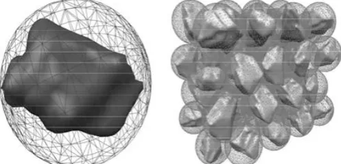
Figure 2: Smallest bounding sphere for a single grain (left) and hexagonal close-packing of equal spheres (right).
Initial Grain Arrangement
For the initial grain arrangement in our mathematical structure model, we rst compute the smallest bounding sphere for each grain by applying an algorithm published by G•artner [10]. The grains are distributed such that a hexagonal close-packing of equal spheres is obtained where the maximum bounding sphere radius is
used for all grains. Examples are shown in Fig. 2. The VSE is created by cutting out the contents of a chosen cuboidal bounding box. It is well-known that a hexagonal close-packing of equal spheres can fill up space with a density of
Π /∛2= 74 %
Considering this information, we can increase the bounding sphere radii if the grain volume fraction in the VSE is larger than required by an investigated grinding wheel speci cation. Hence, the target value can be matched exactly. On the other hand, we have to compact the grains if the grain volume fraction is too low. This is discussed next.
Compaction of Grains
The compaction of the grains in a chosen bounding box representing the VSE has to be done collision-free. We have developed an algorithm which moves the grains into the direction of the center point of the bounding box or to one of the three coordinate planes through the center point. The moving direction can be randomized by allowing a deviation from the original direction. Then, the maximum possible moving length without collision with another grain is computed. The algorithm passes through a list of the grains which is sorted depending on the distance of the grains to the center point/plane, i.e., the rst translation is calculated for the grain closest to the center point/plane. In addition to translation, it is also possible to rotate the grains before moving them. For this purpose, bounding ellipsoids of the grains are computed by using a variant of Khachiyan's algorithm. The grains are temporarily rotated around the principal axes of their ellipsoid to nd the case with the best possible moving length which determines the actual rotation. The algorithm for the case with the bounding box center point as the target point is summarized in Alg. 1.
For an efficient collision detection, a pre selection of necessary intersection tests is done, e.g., by sorting out mesh faces which lie on the back side of a grain regarding the moving direction such that they cannot be intersected when translating the grain. Furthermore, the number of intersection calculations is reduced considerably by applying simple and fast tests such as the detection of bounding sphere intersections first.
An example for a VSE containing 125 grains generated as randomized tetrahe-dra is illustrated in Fig. 3. In the initial arrangement, the depicted bounding box contains a grain volume fraction of about 16:1 %. After ve iterations by only trans-lating into the direction of the centre point (without any randomized deviation from that direction), the grain volume fraction is increased to 38:7 %. The increase from the fourth to the fifth step is only 0:1 percentage point. However, one additional iteration in which also rotations in steps of five degrees are applied leads to a further significant increase to 48:8 %. With the parameters applied in this example, a max-imum grain volume fraction of about 54 % is attainable by continuing the iterative process.
When the VSE is created, the grains have to be cut with the bounding box as visible on the right-hand side of Fig. 3. Hence, the resulting polygons on the six bounding planes of the box have to be remeshed. In the case of convex grains, the above-mentioned Quickhull algorithm can be used for this purpose. In the case of non-convex grains from CT scan data, the polygons on the bounding planes can also be non-convex and they can contain holes. Then, we apply the mesh generator Triangle by Shewchuk.
Tetrahedral Mesh Generation
Once a VSE has been created, we can apply the tetrahedral mesh generator Tet-Gen to mesh the interior of the domain. As a constraint, the maximum tetra-hedral cell volume can be prescribed. In the future, we want to use the tetrahedral meshes for nite element simulations to predict the change of the grinding wheel topography, e.g., by grain break-out or bond fracturing, depending on material properties. Currently, we make use of the tetrahedral meshes for the generation of ceramic bond as explained in the next section.
Ceramic Bond Modeling
Ceramic-bonded grinding wheels are produced by a sintering process. Grains and bonding material in powder form are mixed and pressed into a mold. The bonding material is liquefied under high heat such that it flows around the grains. When the bonding material solidifies after the heating, bond bridges are formed between the grains. Due to the minimization of the surface tension, these bond bridges correspond to minimal surfaces.
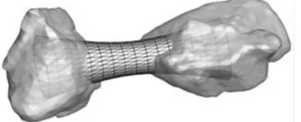
Figure 4: Grains with bond bridge modeled by surface mesh (translucent view).
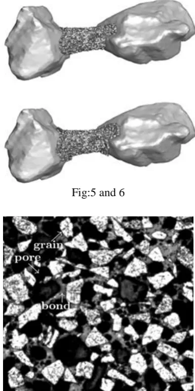
bond depending on the distance between the grain centers. For each of the two grains of a bonded connection, we compute the largest possible circle which is perpendicular to the axis through the two grain centers and which lies completely inside the particular grain. Since the bond meshes intersect the grain meshes, we only use them to determine the tetrahedral volume cells which de ne a bond bridge. This is done by nding intersections between tetrahedra and the bond surface meshes. The result for the example is presented in Fig. 5. For a more realistic rounded connection of the bond bridges to the surfaces of the grains, we grow the bond bridges at the grains by introducing further layers of tetrahedral bond cells. One layer contains potential new bond cells which are tetrahedral cells being adjacent to bond cells and connected to grain triangle faces. Depending on the angle between the bond bridge axis and the normal vector of the grain face, a potential bond cell is introduced as new bond cell or not. If the angle is zero, the bond bridge axis is perpendicular to the triangle face. Hence, it is reasonable to add more layers of bond cells for small angles than for large angles where a rounded connection of a bond bridge to a grain already exists. The result for the example of Fig. 5 after three bond growth iterations for maximum angles of 30 , 60 and 90 , respectively, is illustrated in Fig. 6.
By iteratively adapting the radii of the circles in the middle of each bond bridge, we make sure that a prescribed bond volume fraction for the whole VSE is met. The algorithm for the ceramic bond modeling is summarized in Alg. 2.
A part of a structure cut of a specimen, recorded by light-optical microscopy, can be seen in Fig. 7. The original picture as shown below shows an area of 4 mm 4 mm from which we have taken a part with a size of approximately 0:8 mm 0:8 mm here. The specimen contains CBN grains with a mean grain size of 91 m. It has a grain volume fraction of 40 % and a bond volume fraction of 20 %. A slice through a modeled VSE with randomized tetrahedra generated for the same parameters is depicted in Fig. 8. Both pictures re ect the dense packing of the grains and the bond bridges.
Fig:5 and 6
Figure 7: Structure cut of a specimen with CBN grains and ceramic bond.
Figure 8: Slice through a VSE with randomized tetrahedra and the same grain andbond volume fractions
II.
CONCLUSION
In this paper, we have presented an approach for modeling ceramic-bonded grinding wheel structures. Our model incorporates non-convex grains from CT scan data as well as simplied convex grains. The grains are triangulated and the resulting meshes are decimated if necessary. The initial step for modeling a volumetric element of a grinding wheel is the computation of the smallest bounding sphere for each grain and the subsequent arrangement of the grains according to a hexagonal close-packing of equal spheres. To obtain larger grain volume fractions, the grains in our model can be compacted using our collision-free rotation and translation algorithm. After a tetrahedralization of the VSE, ceramic bond bridges between the grains can be modeled by computing approximated minimal surfaces and by bonding all tetrahedral volume surfaces.
III. FUTURE WORK
In future investigations, we want to take into account grain fracturing, grain break-out and bond fracturing for an appropriate modeling of the grinding wheel topography. This can be done by considering statistical distribution functions determined by experiments or by modeling material properties. A verification of our model should then be done for different grinding wheel speculations.
IV. REFERENCES
[1]. F. Klocke, Manufacturing Processes 2 - Grinding, Honing, Lapping, SpringerVerlag Berlin Heidelberg, 2009.
[2]. I. D. Marinescu, M. P. Hitchiner, E. Uhlmann, W. B. Rowe & I. Inasaki, Handbook of Machining with Grinding Wheels, CRC Press, 2006.
[3]. H. K. T•onsho, J. Peters, I. Inasaki & T. Paul, Modelling and Simulation of Grinding Processes, CIRP Annals - Manufacturing Technology, 41 (2), 677-688,1992.
[4]. D. A. Doman, A. Warkentin & R. Bauer, A survey of recent grinding wheel topography models, International Journal of Machine Tools and Manufacture,46 (3-4), 343-352, 2006.
[5]. E. Brinksmeier, J. C. Aurich, E. Govekar, C. Heinzel, H.-W. Homeister,F. Klocke, J. Peters, R. Rentsch, D. J. Stephenson, E. Uhlmann, K. Weinert& M. Wittmann, Advances in Modeling and Simulation of Grinding Processes, CIRP Annals Manufacturing Technology, 55 (2), 667-696, 2006.
[6]. K.-H. Brakhage, M. Makowski, F. Klocke & M. Weiss, Grinding Wheel Modeling: Development of a Mathematical Model, in Proceedings of MASCOT11-IMACS/ISGG Workshop, IMACS Series in Computational and Applied Mathematics, 17, 31-40, 2013.
[7]. L. Kobbelt, S. Campagna & H.-P. Seidel, A General Framework for Mesh Decimation, in Proceedings of Graphics Interface, 43-50, 1998.
[8]. C. B. Barber, D. P. Dobkin & H. Huhdanpaa, The Quickhull algorithm for Convex Hulls, ACM Transactions on Mathematical Software, 22 (4), 469-483,1996.
[9]. B. G•artner, Fast and Robust Smallest Enclosing Balls, in Proceedings of the 7th Annual European Symposium on Algorithms, 325-338, 1999.
[10]. J. Conway & N. J. A. Sloane, Sphere Packings, Lattices and Groups, 3rd ed., Springer-Verlag New York, 1999. [11]. M. J. Todd & E. A. Yildirim, On Khachiyan's
Algorithm for the Computation of Minimum-Volume Enclosing Ellipsoids, Discrete Applied Mathematics, 155(13), 1731-1744, 2007.
[12]. J. R. Shewchuk, Triangle: Engineering a 2D Quality Mesh Generator and Delaunay Triangulator, in Applied Computational Geometry: Towards Geometric Engineering, volume 1148 of Lecture Notes in Computer Science, 203-222, SpringerVerlag Berlin Heidelberg, 1996.
[13]. H. Si, TetGen, a Delaunay-Based Quality Tetrahedral Mesh Generator, ACM Transactions on Mathematical Software, 41 (2), 11:1-11:36, 2015.