Volume 2007, Article ID 29081,22pages doi:10.1155/2007/29081
Research Article
Robust Feature Detection for Facial Expression Recognition
Spiros Ioannou, George Caridakis, Kostas Karpouzis, and Stefanos Kollias
Image, Video and Multimedia Systems Laboratory, National Technical University of Athens, 9 Iroon Polytechniou Street, 157 80 Zographou, Athens, Greece
Received 1 May 2006; Revised 27 September 2006; Accepted 18 May 2007
Recommended by J¨orn Ostermann
This paper presents a robust and adaptable facial feature extraction system used for facial expression recognition in human-computer interaction (HCI) environments. Such environments are usually uncontrolled in terms of lighting and color quality, as well as human expressivity and movement; as a result, using a single feature extraction technique may fail in some parts of a video sequence, while performing well in others. The proposed system is based on a multicue feature extraction and fusion technique, which provides MPEG-4-compatible features assorted with a confidence measure. This confidence measure is used to pinpoint cases where detection of individual features may be wrong and reduce their contribution to the training phase or their importance in deducing the observed facial expression, while the fusion process ensures that the final result regarding the features will be based on the extraction technique that performed better given the particular lighting or color conditions. Real data and results are pre-sented, involving both extreme and intermediate expression/emotional states, obtained within the sensitive artificial listener HCI environment that was generated in the framework of related European projects.
Copyright © 2007 Spiros Ioannou et al. This is an open access article distributed under the Creative Commons Attribution License, which permits unrestricted use, distribution, and reproduction in any medium, provided the original work is properly cited.
1. INTRODUCTION
Facial expression analysis and emotion recognition, a re-search topic traditionally reserved for psychologists, has gained much attention by the engineering community in the last twenty years. Recently, there has been a growing interest in improving all aspects of the interaction between humans and computers, providing a realization of the term “affective computing.” The reasons include the need for quantitative facial expression description [1] as well as automation of the analysis process [2] which is strongly related to ones’ emo-tional and cognitive state [3].
Automatic estimation of facial model parameters is a dif-ficult problem and although a lot of work has been done on selection and tracking of features [4], relatively little work has been reported [5] on the necessary initialization step of tracking algorithms, which is required in the context of facial feature extraction and expression recognition. Most facial ex-pression recognition systems use the facial action coding sys-tem (FACS) model introduced by Ekman and Friesen [3] for describing facial expressions. FACS describes expressions us-ing 44 action units (AU) which relate to the contractions of specific facial muscles. In addition to FACS, MPEG-4 met-rics [6] are commonly used to model facial expressions and
underlying emotions. They define an alternative way of mod-eling facial expressions and the underlying emotions, which is strongly influenced by neurophysiologic and psychological studies. MPEG-4, mainly focusing on facial expression syn-thesis and animation, defines the facial animation parame-ters (FAPs) that are strongly related to the action units (AUs), the core of the FACS. A comparison and mapping between FAPs and AUs can be found in [7].
Most facial expression recognition systems attempt to map facial expressions directly into archetypal emotion cat-egories while been unable to handle expressions caused by intermediate or nonemotional expressions. Recently, several automatic facial expression analysis systems that can also dis-tinguish facial expression intensities have been proposed [8–
cameras, [24–27] require per-user or per-expression train-ing either on the expression recognition or the feature ex-traction or cope only with fundamental emotions. From the above, [8,13,21,23,25,27] provide success results solely on expression recognition and not on the feature extrac-tion/recognition. Additionally very few approaches can per-form in near real time.
Fast methodologies for face and feature localization in image sequences are usually based on calculation of the skin color probability. This is usually accomplished by calculating the a posteriori probability of a pixel belonging to the skin class in the joint Cb/Cr domain. Several other color spaces have also been proposed which exploit specific color charac-teristics of various facial features [28]. Video systems, on the other hand, convey image data in the form of one compo-nent that represents lightness (luma) and two compocompo-nents that represent color (chroma), disregarding lightness. Such schemes exploit the poor color acuity of human vision: as long as luma is conveyed with full detail, detail in the chroma components can be reduced by subsampling (filtering or av-eraging). Unfortunately, nearly all video media have reduced vertical and horizontal color resolutions. A 4 : 2 : 0 video signal (e.g., H-261, MPEG-2 where each of Cr and Cb are subsampled by a factor of 2 both horizontally and vertically) is still considered to be a very good quality signal. The per-ceived video quality is good indeed, but if the luminance res-olution is low enough—or the face occupies only a small per-centage of the whole frame—it is not rare that entire facial features share the same chrominance information, thus ren-dering color information very crude for facial feature anal-ysis. In addition to this, overexposure in the facial area is common due to the high reflectivity of the face and color al-teration is almost inevitable when transcoding between dif-ferent video formats, rendering Cb/Cr inconsistent and not constant. Its exploitation is therefore problematic in many real-life video sequences; techniques like the one in [29] have been proposed in this direction but no significant improve-ment has been observed.
In the framework of the European Information Technol-ogy projects, ERMIS [30] and HUMAINE [31], a large au-diovisual database was constructed which consists of people driven to emotional discourse by experts. The subjects par-ticipating in this experiment were not faking their expres-sions and the largest part of the material is governed by sub-tle emotions which are very difficult to detect even for human experts, especially if one disregards the audio signal.
The aim of our work is to implement a system capable of analyzing nonextreme facial expressions. The approach has been tested in a real human-computer interaction frame-work, using the SALAS (sensitive artificial listener) testbed [30,31], which is briefly described in the paper. The system should be able to evaluate expressions even when the latter are not extreme and should be able to handle input from various speakers. To overcome the variability in terms of lu-minance and color resolution in our material, an analytic approach that allows quantitative and rule-based expression profiling and classification was developed. Facial expression is estimated through analysis of MPEG FAPs [32], the lat-ter being measured through detection of movement and
de-Eye masks extraction Validation/fusion Mouth masks extraction Validation/fusion
Eyebrow mask extraction Nose detection Eyebrow mask extraction
Anthropometric evaluation Face
detection/ pose correction
Feature points
extraction extractionFAP
Expression recognition Neutral
frame FP
Expression profiles
Figure1: Diagram of the proposed methodology.
formation of local intransient facial features such as mouth, eyes, and eyebrows through time, assuming availability of a person’s neutral expression. The proposed approach is capa-ble of detecting both basic and intermediate expressions (e.g., boredom, anger) [7] with corresponding intensity and con-fidence levels.
An overview of the proposed expression and feature extraction methodologies is given in Section 2 of the pa-per. Section 3describes face detection and pose estimation while Section 4 provides detailed analysis of automatic fa-cial feature boundary extraction and construction of mul-tiple masks for handling different input signal variations.
Section 5 describes the multiple mask fusion process and confidence generation. Section 6 focuses on facial expres-sion/emotional analysis, and presents the SALAS human-computer interaction framework while Section 7 presents the obtained experimental results.Section 8 draws conclu-sions and discusses future work.
2. AN OVERVIEW OF THE PROPOSED APPROACH
An overview of the proposed methodology is illustrated in
Measurement of facial animation parameters (FAPs) re-quires the availability of a frame where the subject’s ex-pression is found to be neutral. This frame will be called the neutral frame and is manually selected from video se-quences to be analyzed or interactively provided to the sys-tem when initially brought into a specific user’s ownership. The final feature masks are used to extract 19 feature points (FPs) [7]. Feature points obtained from each frame are com-pared to FPs obtained from the neutral frame to estimate fa-cial deformations and produce the fafa-cial animation parame-ters (FAPs). Confidence levels on FAP estimation are derived from the equivalent feature point confidence levels. The FAPs are used along with their confidence levels to provide the fa-cial expression estimation.
3. FACE DETECTION AND POSE ESTIMATION
In the proposed approach, facial features including eyebrows, eyes, mouth, and nose are first detected and localized. Thus, a first processing step of face detection and pose estimation is carried out, as described below, to be followed by the ac-tual facial feature extraction process described inSection 4. At this stage, it is assumed that an image of the user at neu-tral expression is available, either a priori or captured before interaction with the proposed system starts.
The goal of face detection is to determine whether or not there are faces in the image, and if yes, return the image lo-cation and extent of each face [34]. Face detection can be performed with a variety of methods [35–37]. In this paper, we used nonparametric discriminant analysis with asupport vector machine(SVM) which classifies face and nonface ar-eas reducing the training problem dimension to a fraction of the original with negligible loss of classification performance [30,38].
800 face examples from the NIST Special Database 18 were used for this purpose. All examples were aligned with respect to the coordinates of the eyes and mouth and rescaled to the required size. This set was virtually extended by apply-ing small scale, translation, and rotation perturbations and the final training set consisted of 16 695 examples.
The face detection step provides a rectangle head bound-ary which includes all facial features as shown inFigure 2. The latter can be then segmented roughly using static an-thropometric rules (Figure 2,Table 1) into three overlapping rectangle regions of interest which include both facial fea-tures and facial background; these threefeature-candidate ar-easinclude the left eye/eyebrow, the right eye/eyebrow, and the mouth. In the following, we utilize these areas to initialize the feature extraction process. Scaling does not affect feature-candidate area detection, since the latter is proportional to the head boundary extent, extracted by the face detector.
The accuracy of feature extraction depends on head pose. In this paper, we are mainly concerned with roll rotation, since it is the most frequent rotation encountered in real-life video sequences. Small head yaw and pitch rotations which do not lead to feature occlusion do not have a significant impact on facial expression recognition. The face detection techniques described in the former section is able to cope with head roll rotations up to 30◦. This is a quite satisfactory
(a) (b)
Figure2: Feature-candidate areas: (a) full frame (352×288), (b) Zoomed (90×125).
Table1: Anthropometric rules for feature-candidate facial areas. Wf,Hf represent face width and face height, respectively.
Area Location Width Height
Eyes and eyebrows Top left and rightparts of the face 0.6Wf 0.5Hf Nose and mouth Bottom part of the face Wf 0.5Hf
range in which the feature-candidate areas are large enough so that the eyes reside in the eye-candidate search areas de-fined by the initial segmentation of a rotated face.
To estimate the head pose, we first locate the left and right eyes in the detected corresponding eye candidate areas. Af-ter locating the eyes, we can estimate head roll rotation by calculating the angle between the horizontal plane and the line defined by the eye centers. For eye localization, we pro-pose an efficient technique using a feed-forward backprop-agation neural network with a sigmoidal activation func-tion. The multilayer perceptron (MLP) we adopted employs Marquardt-Levenberg learning [39,40] while the optimal ar-chitecture obtained through pruning has two 20-node hid-den layers and 13 inputs. We apply the network separately on the left and right eye-candidate face regions. For each pixel in these regions, the 13 NN inputs are the luminance Y, the Cr & Cb chrominance values, and the 10 most important DCT coefficients (with zigzag selection) of the neighboring 8×8 pixel area. Using alternative input color spaces such as Lab, RGB or HSV to train the network has not changed its distinc-tion efficiency. The MLP has two outputs, one for each class, namely, eye and noneye, and it has been trained with more than 100 hand-made eye masks that depict eye and noneye area in random frames from the ERMIS [30] database, in im-ages of diverse quality, resolution, and lighting conditions.
The network’s output in randomly selected facial images outside the training set is good for locating the eye, as shown inFigure 3(b). However, it cannot provide exact outliers, that is, point locations at the eye boundaries; estimation offeature points (FP)is further analyzed in the next section.
(a) (b)
Figure3: (a) Left eye input image (b) network output on left eye, darker pixels correspond to higher output.
the eyes and a small area around them. The size of the tem-plates is half the eye-center distance (bipupil breadth,Dbp). For the following frames, the eyes are located inside the two eye-candidate areas, using template matching which is per-formed by finding the location where the sum of absolute differences (SAD) is minimized.
After head pose is computed, the head is rotated to an upright position and new feature-candidate segmentation is performed on the head using the same rules shown in
Table 1, so as to ensure facial features reside inside their re-spective candidate regions. These regions containing the fa-cial features are used as input for the fafa-cial feature extraction stage, described in the following section.
4. AUTOMATIC FACIAL FEATURE DETECTION AND BOUNDARY EXTRACTION
To be able to compute MPEG-4 FAPs, precise feature bound-aries for the eyes, eyebrows, and mouth have to be extracted. Eye boundary detection is usually performed by detecting the special color characteristics of the eye area [28], by using lu-minance projections, reverse skin probabilities, or eye model fitting [17,41]. Mouth boundary detection in the case of a closed mouth is a relatively easily accomplished task [40]. In case of an open mouth, several methods have been proposed which make use of intensity [17,41] or color information [18,28,42,43]. Color estimation is very sensitive to envi-ronmental conditions, such as lighting or capturing camera’s characteristics and precision. Model fitting usually depends on ellipse or circle fitting, using Hough-like voting or corner detection [44]. Those techniques while providing accurate results in high-resolution images are unable to perform well with low video resolution which lack high-frequency prop-erties; such properties which are essential for efficient corner detection and feature border trackability [4] are usually lost due to analogue video media transcoding or low-quality dig-ital video compression.
In this work, nose detection and eyebrow mask extrac-tion are performed in a single stage, while for eyes and mouth which are more difficult to handle, multiple (four in our case) masks are created taking advantage of our knowledge about different properties of the feature area; the latter are then combined to provide the final estimates as shown in
Figure 1. Tables2and5summarize extracted eye and mouth
mask notation, respectively, while providing a short qualita-tive description. In the following, we use the notationMxkto denote the binary maskkof facial featurex, wherexisefor eyes,mfor mouth,nfor nose, andbfor eyebrows, andLx
de-notes the respective luminance masks. Additionally, feature size and position validation depends on several relaxed an-thropometric constraints; these includetasfm,tec,tb1,t2b,tmb1,tmc2, tmb2,t2n,t3n,t4ndefined inTable 3, while other thresholds de-fined in text are summarized inTable 4.
4.1. Eye boundary detection
4.1.1. Luminance and color information fusion mask
This step tries to refine eye boundaries extracted by the neu-ral network described in Section 3 and denoted as (Me
nn), building on the fact that eyelids usually appear darker than skin due to eyelashes and are almost always adjacent to the iris.
At first, luminance information inside the area depicted by a dilated version ofMe
nnis used to find a luminance thresh-oldte
b:
tbe=
1 3
2fc
Le,Menn
+ minLe, (1)
fc(A,B)=
ci j
, ci j=
⎧ ⎨ ⎩
ai j, bi j=0,
0, bi j=0,
(2)
whereLeis the luminance channel of the eye-candidate area
and•denotes the average over an image area, and min(X) denotes the minimum value of areaX.
When thresholdte
bis applied toLe, a new mask is derived,
denoted asMe
npp. This map includes dark objects near the eye centre, namely, the eyelashes and the iris. From the con-nected components inMe
nppwe can robustly locate the one including the iris by estimating its thickness. In particular, we apply a distance transform using the Euclidean distance metric and select the connected component where distance transform obtains its maximum value DTmax, to produceMe1 mask as illustrated inFigure 4. The latter includes the iris and adjacent eyelashes. The point where the distance transform equals to DTmaxaccurately computes the iris centre.
4.1.2. Edge-based mask
This second approach is based on eyelid detection. Eyelids reside above and below the eye centre, which has already been estimated by the neural network. Taking advantage of their mainly horizontal orientation, eyelids are easily located through edge detection.
Table2: Summary of eye masks.
Described in Detects Depends on Results
Section 4.1.1 Iris and surrounding dark areas including eyelashes Le,Me
nn Me1 Section 4.1.2 Horizontal edges produced by eyelids, residing above and below eye centre Le, eye centre Me 2 Section 4.1.3 Areas of high texture around the iris Le Me 3 Section 4.1.4 Area with similar luminance to eye area defined by maskMe
nn Le,Menn Me4
Table3: Relational anthropometric constraints.
Variable Value Refers to
tm
asf 1% Wf
te
c 5% Wf
tb
2 5% Dbp
tn
2 10% Dbp
tm
b1 10% Iw
tn
4 15% Dbp
tm
c2 25% Dbp
tn
3 20% Dbp
tb
1 30% Dbp
tm
b2 50% Iw
Table4: Adaptive thresholds.
Variable Value Refers to
te b
1 3
2fcLe,Menn
+ minLe
L tb
E
Mb E1
+Mb E1
2 −Mb
E1 2
L tm
c1
Lasfr m
−Lasfr m
2 −Lasfr
m 2
L tm
1
1 3
2Lm+ min
Lm
L tn
1
1 3
Ln+ 2 min
Ln
L tm
2 90% NN output
te
d 90% L
Thresholds
Variable Value
tσ 10−3
tr 128
tvd 0.8
Lx: Luminance image of featurex.
latter looks for gradient continuity only in the vertical direc-tion, thus following half of the possible operator movements. Since edge direction is perpendicular to the gradient, this modified canny operator produces mainly horizontal edge lines, resulting in a mask denoted asMe
b2.
The binary mapsMe
b1andM
e
b2are then combined,
Meb3=Meb1+Meb2, (3)
to produce mapMeb3illustrated inFigure 5(a). Edges directly above and below the eye centre in mapMeb3, which are de-picted by arrows in Figure 5(a), are selected as eyelids and the space between them asMe2, as shown inFigure 5(b).
(a)
170 172 174 176 178 180 182 184 186 188 190 156
154 152 150 148 146 144 142 140
0 0.5 1 1.5 2 2.5 3
(b)
Figure4: (a) Left eye input image (cropped). (b) Left eye maskMe 1 depicting distance transform values of selected object.
4.1.3. Standard-deviation-based mask
Table5: Summary of mouth masks.
Described in Detects Depends on Results
Section 4.4.1 Lips and mouth with similar properties
to ones trained from the neutral frame Mmt, Mouth-candidate image (color) Mm1
Section 4.4.2 Horizontal edges caused by lips Lm Mm 2
Section 4.4.3
Mouth horizontal extent through lip corner detection. Mouth opening through lip edge detection
Lm Mm
3
5 10 15 20 25 30 35 40 45
30 25 20 15 10 5
(a)
(b)
Figure5: (a) Modified canny result. (b) Detected maskMe 2.
We first calculate the standard deviation of the luminance channelLeinn×nsliding blocks resulting inIe
stdn.I e
stdnis
iter-atively thresholded with (1/d)Le, wheredis a divisor
increas-ing in each iteration, resultincreas-ing inMe
sn,d. Whiledincreases,
ar-eas inMe
sn,ddilate, tending to connect with each other.
This operation is performed at first forn =3. The eye centre is selected on the first iteration as the centre of the largest component; for iterationi, the estimated eye centre is denoted as ci and the procedure continues while c1 − ci ≤ Wftec resulting in binary mapMes3,f, as illustrated in Figure 6(a). This is an indication that eye area has exceeded
its actual borders and is now connected to other subfeatures. The same process is repeated withn = 6 resulting in map Me
s6,f illustrated inFigure 6(b). Different block sizes are used
to raise the procedure’s robustness to variations of image res-olution and eye detail information. Smaller block sizes con-verge slower to their final map but the combination of both type of maps results in mapMe3, as in the case ofFigure 6(c), ensuring a better result in case of outliers. Examples of out-liers include compression artifacts, which induce abrupt il-lumination variations. For pixel coordinates (i,j), the above are implemented as follows:
Le=l i,j
,
Ie
stdn=
in,i,j
, in,i,j=
l2
i,j
−li,j
2 ,
mn,d,i,j=
⎧ ⎪ ⎪ ⎪ ⎨ ⎪ ⎪ ⎪ ⎩
1, li,j d > in,i,j,
0, li,j d < in,i,j,
n=3, 6,
Me sn,d =
mn,d,i,j
,
(4)
whered∈(0, max(Le)] and•denotes the mean in then×n
area surrounding (i,j),
fa(A,B)=
ci j
, ci j=ai jbi j,
Me3= fa
Mes2n,f,M e sn,f
. (5)
The above process is similar to a morphological bottom hat operation with the difference that the latter is rather sen-sitive to the structuring element size.
4.1.4. Luminance mask
Finally, a second luminance-based mask is constructed for eye/eyelid border extraction. In this mask, we compute the normal luminance probability ofLeresembling to the mean
luminance value of eye area defined by the NN maskMe
nn. From the resulting probability mask, the areas with a confi-dence interval oftdeare selected and small gaps are closed with
(a) (b) (c)
Figure6: (a)Me
s3,f eye mask forn=3. (b)M
e
s6,f eye mask forn=6. (c)M
e
3, combination of (a) and (b).
Figure7: Left eye maskMe 4.
4.2. Eyebrow boundary detection
Eyebrows are extracted based on the fact that they have a simple directional shape and that they are located on the forehead, which due to its protrusion, has a mostly uniform illumination. Each of the left and right eye and eyebrow-candidate images shown inFigure 2is used for brow mask construction.
The first step in eyebrow detection is the construction of an edge mapMb
Eof the grayscale eye/eyebrow-candidate
image. This map is constructed by subtracting the dilation and erosion of the grayscale image using a line structuring elementstb
2 pixels long and then thresholding the result as shown inFigure 8(a):
MbE1=δs
Le,−ε s
Le,
tEb=
MbE1+MbE12−MbE12
,
MbE=MbE1> tbE,
(6)
whereδs,εsdenote the dilation and erosion operators with
structuring elements, and operator “>” denotes the thresh-olding operator to construct the binary mask MbE. The
se-lected edge detection mechanism is appropriate for eyebrows because it can be directional, it preserves the feature’s original size and can be combined with a threshold to remove smaller skin anomalies such as wrinkles. The above procedure can be considered as a nonlinear high-pass filter.
Each connected component on the edge map is labeled and then tested against a set of filtering criteria. These
cri-(a) (b)
Figure8: (a) Eyebrow candidates. (b) Selected eyebrow maskMb.
teria were formed through statistical analysis of the eyebrow lengths and positions on 20 persons of the ERMIS database [30]. Firstly, the major axis is found for each component through principal component analysis (PCA). All compo-nents whose major axis has an angle of more than 30 degrees with the horizontal plane are removed from the set. From the remaining components, those whose axis length is smaller thant1bare removed. Finally, components with a lateral dis-tance from the eye centre more thantb1/2 are removed and the top-most remaining is selected resulting in the eyebrow mask MbE2. Since eyebrow area is of no importance for FAP
calcula-tion, the result can be simplified easily using (7) resulting in Mbwhich is depicted inFigure 8(b):
Mb=mi,j
,
MbE=
mEi,j
,
mE i,j=
⎧ ⎨ ⎩
1, mi,j=1
∧mi,j=1, j< j, 0 otherwise.
(7)
4.3. Nose localization
1
2 3
7 9
10 8
6 5
4
12
13 11
14
15
18
17 16
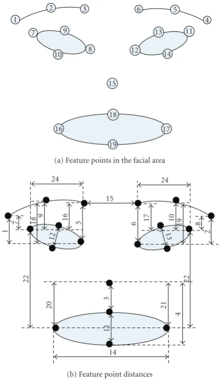
19
(a) Feature points in the facial area 24
15
24
1
7 18 9 16 5
12
6 17 10 19 8
2
13
22
20
3
11
21
4
22
14
(b) Feature point distances
Figure9
The facial area above the mouth-candidate components area is used for nose location. The respective luminance im-age is thresholded bytn1:
tn
1 = 1 3
Ln+ 2 minLn,
Ln: luminance of nose-candidate region.
(8)
Connected objects of the derived binary map are labeled. In bad lighting conditions, long shadows may exist along ei-ther side of the nose. For this reason, anthropometric data [47] about the distance of left and right eyes (bipupil breadth, Dbp) is used to reduce the number of candidate objects: ob-jects shorter thant2nand longer thantn3Dbpare removed. This has proven to be an effective way to remove most outliers without causing false negative results while generating the nostril maskMn1shown inFigure 10(a).
Horizontal nose coordinate is predicted from the co-ordinates of the two eyes. On mask Mn1, each of the con-nected component horizontal distances from the predicted nose centre is compared to the average internostril distance that is approximatelyt4nDbp [47], and components with the
(a) (b)
Figure10: (a) Nostril candidates, (b) selected nostrils.
largest ones are considered as outliers. Those who qualify en-ter two separate lists, one including left-nostril candidates and one with right-nostril candidates based on their prox-imity to the left or right eye. Those lists are sorted according to their luminance and the two objects with the lowest values are retained from each list. The largest object is finally kept from each list and labeled as the left and right nostril, respec-tively, as shown inFigure 10(b). The nose centre is defined as the midpoint of the nostrils.
4.4. Mouth detection
4.4.1. Neural network lip and mouth detection mask
At first, mouth boundary extraction is performed on the mouth-candidate facial area depicted inFigure 2. An MLP neural network is trained to identify the mouth region using the neutral image. Since the mouth is closed in the neutral image, a long low-luminance region exists between the lips. The detection of this area, in this work, is carried out as fol-lows.
The initial mouth-candidate luminance imageLmshown
inFigure 11(a)is simplified to reduce the presence of noise, remove redundant information, and produce a smooth im-age that consists mostly of flat and large regions of inter-est. Alternating sequential filtering by reconstruction (ASFR) (9) is thus performed on Lm to produce Lm
asfr shown in
Figure 11(b). ASFR ensures preservation of object bound-aries through the use of connected operators [48],
fasfr(I)=βnαn· · ·β2α2β1α1(I), n=1, 2,. . .,
αr(I)=ρ−(f rB| f), βr(I)=ρ+(f ⊕rB| f),
r=1, 2,. . ., ρ+(−)(g| f) : reconstruction closing (opening)
of f by markerg,
(9)
where the operations⊕anddenote the Minkowski dilation and erosion.
To avoid over simplification, the ASFR filter is applied with a scale ofn ≤ dw
m·tmasf, wheredwm is the width ofLm.
The luminance image is then thresholded bytm1:
tm
1 = 1 3
2Lm+ minLm
asfr
(a) (b) (c)
Figure11: Extraction of training image: (a) initial luminance mapLm, (b) filtered imageLm
asfr, (c) extracted maskMmt1.
(a) (b)
Figure12: (a) Luminance image, (b) NN mouth maskMm 1.
and connected objects on the resulting binary maskMm t1 are
labeled as shown inFigure 11(c).
The major axis of each connected component is com-puted through PCA analysis, and the one with the longest axis is selected. The latter is subsequently dilated vertically and the resulting maskMmt is produced, which includes the
lips. MaskMmt shown inFigure 11(c)is used to train a neural
network to classify the mouth and nonmouth areas accord-ingly. The image area included by the mask corresponds to the mouth class and the image outside the mask to the non-mouth one. The perceptron has 13 inputs and its architecture is similar to that of the network used for eye detection.
The neural network trained on the neutral-expression frame is then used on other frames to produce an estimate of the mouth area: neural network output on the mouth-candidate image is thresholded bytm2 and those areas with high confidence are kept to form a binary map containing several small subareas. The convex hull of these areas is cal-culated to generate maskMm
1 as shown inFigure 12.
4.4.2. Generic edge connection mask
In this second approach, the mouth luminance channel is again filtered using ASFR for image simplification. The hor-izontal morphological gradient ofLmis then calculated
sim-ilarly to the eyebrow binary edge map detection resulting in Mmb1 shown inFigure 13(a). Since the nose has already been detected, its vertical position is known. The connected el-ements of Mmb1 are labeled and those too close to the nose are removed. From the rest of the map, very small objects (less thantmb1Iw, whereIw is the map’s width) are removed.
(a) (b)
Figure13: (a) Initial binary edge map. (b) Output maskMm b2.
Figure14: Mouth-candidate area depicting nonuniform illumina-tion.
Morphological closing is then performed so that those whose distance is less thantmb2Iw connect together, in order to
ob-tain maskMmb2as shown inFigure 13(b). The longest of the remaining objects in horizontal sense is selected as mouth maskMm2.
4.4.3. Lip-corner luminance and edge information fusion mask
The problem of most intensity-based methods that try to estimate mouth opening is the visibility of upper teeth, es-pecially if they appear between the upper and lower lip al-tering saturation and intensity uniformity as illustrated in
Figure 14.
(a) (b) (c)
(d) (e)
Figure15: (a) MaskMm
c1with removed background outliers, (b) maskM m
c2with apparent teeth, (c) horizontal edge maskM m
c3, (d) output
maskMm
3, (e) input image.
thresholded using a low thresholdtm
c1providing an estimate of the mouth interior area, or the area between the lips in case of a closed mouth. The threshold used is estimated adap-tively:
Mmc1a=L m
asfr< tcm1,
tcm1=
Lmasfr−Lmasfr2−Lmasfr2
, (11)
where operator “<” again stands for the thresholding process. In the resulting binary map, all connected objects adjacent to the border are removed, thus removing fa-cial background outliers, resulting in mask Mm
c1 shown in Figure 15(a). We now examine two cases separately: either we have no apparent teeth and the mouth area is denoted by a cohesive dark area (case 1) or teeth are apparent and thus two dark areas appear at both sides of the teeth (case 2). It should be noted that those areas appear even in large ex-tensive smiles. The largest connected object is then selected fromMm
c1 and its centroid is found. If the horizontal
posi-tion of its centroid is near the horizontal nose posiposi-tion, case 1 is selected, otherwise case 2 is assumed to occur and two dark areas appear at both sides of the teeth. To assess hori-zontal noise centre proximity, we use a distance threshold of tm
c2Dbp. The two cases are quite distinguishable through this process. In case 2, the second largest connected object is also selected. A new binary map is created containing either one object in case 1 or both objects in case 2; the convex hull of this map is then calculated and maskMm
c2 is produced,
de-picted inFigure 15(b).
The detected lip corners provide a robust estimation of mouth horizontal extent but are not adequate to detect mouth opening. Therefore, maskMm
c2is expanded to include
the lower lips. An edge map is created as follows: the mouth image gradient is calculated in the horizontal direction, and
is thresholded by the median of its positive values, as shown inFigure 15(c). This mask, denoted asMm
c3, contains objects
close to the lower middle part of the mouth, which are some-times missed because of the lower teeth. The two masks,Mm c2
and Mm
c3, have to be combined to a final mask. An
effec-tive way of achieving this is to keep from both masks ob-jects which are close to each other. SinceMm
c2 may contain
objects belonging to lower parts of the mouth area, it is ex-panded downwards by dilation with a nonsymmetric vertical structuring element, resulting in maskMm
c2d. Morphological
reconstruction [49] is then used to combine the masks to-gether by using the area belonging to bothMm
c3 andM
m c2d as
input and objects belonging to either mask (12) as marker. Final maskMm3 is shown inFigure 15(d),
Mm c23= fa
Mm c3,M
m c2d
, fa(A,B)=
ci j
, ci j=
ai jbi j
,
fo(A,B)=
ci j
, ci j=
ai j,bi j=0
bi j,ai j=0
,
Mm3 =ρ
Mmc23,fo
Mmc2d,M m c3
,
(12)
whereρ(B,A) denotes the reconstruction ofAwith marker B.
5. FINAL MASKS GENERATION AND CONFIDENCE ESTIMATION
Figure16: Noisy color and edge information cause problems in the extraction of this mask.
changes and compression artifacts cannot be predicted and so individual masks have to be re-evaluated and combined on each new frame.
5.1. Validation of eye and mouth masks
The proposed algorithms presented in Section 4produce a maskMbfor each eyebrow, nose coordinates, four
interme-diate mask estimates Me1...4 for each eye and three interme-diate mouth mask estimatesMm1...3. The four masks for each eye and three mouth masks must be fused to produce a final mask for each feature. Since validation can only be done on the end result of each intermediate mask, we unfortunately cannot give different parts of each intermediate mask dif-ferent confidence values, so each pixel of those masks will share the same value. We propose validation through testing against a set of anthropometric conformity criteria. Since, however, some of these criteria relate either to aesthetics or to transient feature properties, we cannot apply strict anthro-pometric judgment.
For each maskkof featurex, we employ a set of valida-tion measurementsVx
k,i, denoted byi, which are then
com-bined to a final validation tagVx
k,f for that mask. Each
mea-surement produces a validation estimate value depending on how close it is to the usually expected feature shape and po-sition, in the neutral expression. Expected values for these measurements are defined from anthropometry data [33] and from images extracted from video sequences of 20 per-sons in our database [30]. Thus, a validation tag between [0,1] is attached to each mask, with higher values denoting proximity to the most expected measurement values.
All validation measurements are based on distances de-fined inTable 6. Given these definitions, eye mask validation is based on four tags specified inTable 7, concerning indi-vidual eye dimensions, relations between the two eyes and relations between each eye and the corresponding eyebrow. Finally, mouth map validation is based on four tags referring to distance measurements specified inTable 8. In the follow-ing, validation value of measurementifor maskkof featurex will be denoted asVkx,i∈[0, 1] whereVkx,iis forced into [0,1],
that is, ifVkx,i>1, thenVkx,i=1 and ifVkx,i<0, thenVkx,i=0.
We want masks with very low validation tags to be dis-carded from the fusion process and thus those are also
pre-Table6: Mask validation distances.
d1 Distance of eye’s top horizontal coordinate andeyebrow’s middle bottom horizontal coordinate d2 Eye width
d3 Eye height
d4 Distance of eye’s middle vertical coordinate andeyebrow’s middle vertical coordinate d5 Eyebrow width
d6 Dbp, bipupil breadth
d7 Distance of eye’s middle vertical coordinate frommouth’s middle vertical coordinate d8 Mouth width
d9 Mouth height
d10 Sellion-Stomion length d11 Sellion-Subnasion length
vented from contribution on final validation tags; therefore, we ignore those withVx
k,f < (tvd· Vkx,ii). Final validation
tag for maskkis then calculated as follows:
Vkx,f =
Vkx,i
i, i:Vkx,i≥tvd
Vkx,i
i,i∈Nn. (13)
5.2. Mask fusion
Each of the intermediate masks represents the best-effort result of the corresponding mask-extraction method used. Multiple eye and mouth masks must be merged to pro-duce final mask estimates for each feature. The mask fu-sion method is based on the assumption that having multiple masks for each feature lowers the probability that all of them are invalid since each of them produces different error pat-terns. It has been proven in committee machine (CM) theory [50,51] that for the desired outputtthe combination error ycomb−tfrom different machinesfiis guaranteed to be lower
than the average error:
ycomb= 1
M
yi,
ycomb−t2= 1
M
i
yi−t
2
− 1
M
i
yi−ycomb
2 .
(14)
Since intermediate masks have a validation tag which represents their “plausibility” of being actual masks for the feature they represent, it seems natural to combine them by giving more credit to those which have a higher validation value on one hand, and on the other to ignore those that we are sure will not contribute positively on the result. Fur-thermore, according to the specific qualities of each input, we would like to favor specific masks that are known to perform better on those inputs, that is, give more trust to color-based extractors when it is known that input has good color quality, or to the neural network-based masks when the face resolu-tion is enough for the network to perform adequate border detection.
Table7: Anthropometric validation measurements used for eye masks. Note that (eye width)/(bipupil breadth)=0.49 [33].
Validation tag Measurement Description
Ve
k,1 1−d1
/d6/4
−1 Distance of the eye’s topmost centre from the corresponding eyebrow’s bottom centre. Ve
k,2 1−1−
d2/d6
/0.49 Eye width compared to left & right eye distance. Ve
k,3 0.3−
d3−d2
/d2 Relation of eye width and height
Ve
k,4 1−d4/d5 Horizontal alignment of the eye and respective eyebrow
Table8: Anthropometric validation measurements used for mouth masks. Note that (bichelion breadth)/(bipupil breadth)= 0.82 and (stomion-subnasion length)/(bipupil breadth)=0.344 [33].
Validation tag Measurement Description
Vm
k,1 1−d7/d6 Horizontal mouth centre, in comparison with theinter-eye centre coordinate. Vm
k,2 1−
d8
d6 1 0.82−1
Mouth width in comparison with bipupil breadth
Vm
k,3 1 ifd9<
1.3d6
elsed9/
1.3d6
Mouth height in comparison with bipupil breadth
Vm
k,4 1− 1−
d10−d11
d6 1 0.344
Nose distance from top lip
nonsynthetic training data for the latter is difficult to acquire, we have found that a good estimator can be the chromatic de-viation measured on the face skin area: very large variability in chromatic components is a good indicator for color noise presence. Therefore,σCr,σCb are less thantσ for good color
quality and much larger for poor quality images. Regarding resolution, we have found that the proposed neural-network-based detector performs very well in sequences whereDbp> trpixels, whereDbpdenotes the bipupil breadth.
In the following, we use the following notation: final masks for left eye, right eye, and mouth are denoted as before asMeL
f,M eR
f,Mmf. For intermediate maskkof featurex,
vari-ableVkx,f determines which masks are favored according to
their final validation values and variablegkdetermines which
masks extractors are favored according to input characteris-tics. Moreover, each pixel-element on the final mask Mxf is denoted asmxf and each pixel-element on thekth
interme-diate maskMxkasmxk,k ∈ Nn, where pixel coordinates are
omitted for clarity. Moreover, since we would like masks to be fused in a per-pixel basis, not all pixels on an output mask will necessarily derive from the same intermediate masks. Therefore, each pixel on the output mask will have a valida-tion valuevxf which will reflect mask validation and extractor
suitability of the masks it derived; values ofvxf for all pixels
form validation values of final mask,Vx f.
Let us denote the function betweenmxf ∈ {0, 1},vxf ∈
0, 1, andmx
k∈ {0, 1}as
vx
f = f
mx k;Vkx,f,gk
,
mx
f =F
vx f
, (15)
then our requirements can be expressed as follows.
(1) If all masks k agree that a pixelmxk does not belong
to the featurex, then this should be reflected on the
fusion result regardless of validation tagsVkx,f:
if∀k∈Nn, mkx=0=⇒mxf =0. (16)
(2) We require that gating variablegkshould be balanced
according to the number of masks:
n
k=1
gk=n. (17)
(3) If all maskskagree that a pixelmx
f does belong to
fea-turexwith maximum confidence, then this should be reflected on the fusion result:
if∀k∈Nn, mxk=1∧Vkx,f =1=⇒mxf =1,vxf =1.
(18)
(4) If all maskskhave failed, then no mask should be cre-ated as a fusion result:
∀k∈Nn, Vkx,f =0=⇒mxf =0. (19)
(5) If one mask has failed, then the result should depend only on remaining masks:
∃k0∈Nn:Vkx0,f =0=⇒m
x
f = f
k∈Nn−{k0}
mxk;Vkx,f,gk
.
(20)
(6) Fusion with a better input mask should produce a higher value on the output for the pixels deriving from this mask:
ifVx1
k0,f > V
x2
k0,f, ∀k∈Nn−
k0, it isVx1
k,f =V x2
k,f and the same holds for all
mxj
k =0, gk,j, j=1, 2 thenv x2
f > v x2
f .
Input f1 f2 . . . fn
y1,V1
y2,V2
yn,Vn g1 g2 gn V o ting Output Gate
Figure17: The dynamic committee machine model.
(7) If an input mask derives from a more trusted mask ex-tractor, then pixels deriving from this mask should be associated with a higher value:
ifgk,1> gk,2, ∀k∈N
n−
k0it isVx1
k,f =V x2
k,f,
and the same holds for allmxj
k =0, V
xj
k,f, j=1, 2
thenvx2
f > v x2
f .
(22)
To fulfill these requirements in this work, we propose a fusion method based on the idea of dynamic committee ma-chines (DCM) which is depicted inFigure 17. In a static CM, the voting weight for a component is proportional to its er-ror on a validation set. In DCMs, input is directly involved in the combining mechanism through a gating network (GN), which is used to modify those weights dynamically.
The machine’s inputs are intermediate masksMxk,Vx k,f is
considered as the confidence of each input and variablegk
has a “gating” role. Final masksMeL f,M
eR
f ,Mmf are considered
as the machine’s output.
Each pixel-elementmxf on the final maskMxfis calculated
from thenmasks as follows:
fmx k;Vkx,f,gk
= 1 n n k=1 mx
kVkx,fgk, (23)
Fvx f = ⎧ ⎨ ⎩
0, vxf <
Vxf
|vxf >0
,
1, otherwise. (24)
The role of gating variable gk is used to favor color-aware
feature extraction methods (Me1,Mm1) in images of high-color quality and resolution; gating variablegiis defined as follows:
gk=
⎧ ⎪ ⎪ ⎪ ⎪ ⎪ ⎨ ⎪ ⎪ ⎪ ⎪ ⎪ ⎩ n−
n−1 n
, k=1, Dbp> tr, σCr< tσ,σCb< tσ,
1
n, k=1, Dbp> tr, σCr< tσ,σCb< tσ,
1, otherwise,
(25)
whereDbpthe bipupil width in pixels,σCr,σCbthe standard deviation of the Cr, Cb channels, respectively, inside the facial area. It is not difficult to see that (23)–(25) satisfy (16)–(22). Tables9and10illustrate mask fusion examples for the left eye and mouth where some of the masks are problem-atic. Validation tags refer to the corresponding mask valida-tion tag whileDbpis quoted as an indication of the sequence
resolution. For illustration purposes, the feature points ex-tracted from the final masks are presented verifying the pre-cise extraction of the features and feature points, based on the mask fusion process.
5.3. Eye, eyebrow, and mouth mask confidence
estimation
Confidence values are needed for expression analysis and are thus propagated from mask extraction to the corresponding FPs, FAPs, and the expression evaluation stage. Their role is to indicate the confidence that a given feature has been correctly extracted and therefore the measure by which ex-pression analysis should rely on a specific feature. To esti-mate confidence, we have used extracted feature resemblance to mean anthropometry data from [33]. Since data for eye-brow sizes was not available in the literature, confidence val-ues were expanded to rely also on information such as facial feature size constancy and face symmetry.
Confidence values can be attached to each final mask and are denoted asCe,Cb,Cm ∈ [0, 1]. Confidence values vary
between 0 and 1 with the latter indicating the best case. For the nose, no confidence value is estimated and is always as-sumed thatCn=1. Those values are generated through a set
of criteria, which complement final validation tagsVf used
for fusion; these criteria relate to
(1) size constancy over time, producingCbmed,Cemed; (2) face symmetry, producingCe
s;
(3) and anthropometric measurement conformance, pro-ducingCe1,Ce2,C1m.
These values are calculated as follows.
(1) With the exception of mouth, facial feature width is mostly constant even in intense expressions. Measured width for eyebrowswbi and each of the eyesweiL,wieR is examined
in each frameithe median valuewxover the last 10 frame
period for featurexis calculated. In each frame, similarity betweenwxi andwxon the last 10 frames is used as an
esti-mate forCbmedfor the eyebrows andCemedfor the eyes:
Cxmed,i=1−wxi −med
wxj, j=i−10. . . iwxi
−1 . (26)
(2)Ce
s ∈[0, 1] denotes shape similarity between the left
and right upper eyelid; exploiting the symmetry of the face, we estimate the resemblance between the upper parts of left and right eyelids. Let us defineXL,XRas matrices containing
the horizontal coordinates of the left and right upper eyelid boundaries; a valueCsindicating their similarity can be
cal-culated as a two-dimensional correlation coefficient between the two vectors,
Ce s= n XL n−
XLXR
n− XR n XL n−
XL2 n
XR
n−
XR2
Table9: Examples of mask fusion on the left eye with corresponding validation tags and detected feature points.
Sequence-frame kk-1002 Vef kk-1998 Vef rd-12259 Vef al-27 Vef Mask
Me nn
Me1 0.825 0.813 0.823 0.839
Me
2 0.782 0.581 0.763 0.810
Me3 0.866 0.733 0.716 0.787
Me
4 0.883 0.917 0.826 0.872
Mef
FPs
Dbp: 58 px Dbp: 58 px Dbp: 96 px Dbp: 36 px Dbpdenotes bipupil breadth in pixels and is quoted as an image resolution indicative.
Table10: Examples of mouth mask fusion with corresponding val-idation tags and detected feature points.
Sequence-frame kk-1014 Vm
f rd-1113 Vmf Mask
Mm1 0.820 0.538
Mm
2 0.868 0.752
Mm3 0.828 0.821
Mmf
FPs
(3)Ce,Cm,Cbare calculated using measurements based
on anthropometry from [33].Table 11summarizes estima-tion ofC1e,C2e,Cm1.
Confidence values for features are estimated by averaging on the previously defined criteria and final mask validation tags as follows:
Ce=Ve
f,C1e,C2e,Ces,Cmede
,
Cm=Vm f ,C1m
,
Cb=Cb
med.
(28)
6. EXPRESSION ANALYSIS
An overview of the expression recognition process is shown in Figure 1. At first, 19 feature points (FPs) are calculated from the corresponding feature masks. Those FPs have to be compared with the FPs of the neutral frame, so as to measure movement and estimate FAPs. FAPs are then used to evaluate expression profiles, providing the recognized expression.
6.1. From masks to feature points
Left-, right-, top-, and bottom-most coordinates of the final masksMeL
f,M eR
f ,Mmf, left right and top coordinates ofM bL
f ,
MbR
f , as well as nose coordinates, are used to define the 19
feature points (FPs) shown inTable 12, Figures18and9(a). Feature pointxis then assigned with confidenceCFP
x by
in-heriting the confidence level (Ce,Cm, Cb,Cn) of the final
Table11: Anthropometric evaluation [33] for eye and mouth loca-tion and size.
Description Confidence measure
Bientocanthus breadth Da
7
Biectocanthus breadth Da
5
Bicheilion breadth Da
10 (Da
5−Da7)/2 Daew Eye position/eye distance Ce
1=1−Dan5 −D5n/Dan5
Eye width Ce
2=1−Danew−Dnew/Danew
Mouth Cm
1 =1−D10an−D10n/Dan10
Dan
i =Dxa/Da7:adenotes that distanceiderives from [33];ndenotes
that value is normalized by division withDa
7.
Table12: Feature points.
FP no. MPEG-4 FP [6] FP name
01 4.5 Outer point of left eyebrow
02 4.3 Middle point of left eyebrow
03 4.1 Inner point of left eyebrow
04 4.6 Outer point of right eyebrow
05 4.4 Middle point of right eyebrow
06 4.2 Inner point of right eyebrow
07 3.7 Outer point of left eye
08 3.11 Inner point of left eye
09 3.13 Upper point of left eyelid
10 3.9 Lower point of left eyelid
11 3.12 Outer point of right eye
12 3.8 Inner point of right eye
13 3.14 Upper point of right eyelid 14 3.10 Lower point of right eyelid
15 9.15 Nose point
16 8.3 Left corner of mouth
17 8.4 Right corner of mouth
18 8.1 Upper point of mouth
19 8.2 Lower point of mouth
6.2. From FP to FAP estimation
A 25-dimensional distance vector (Dv) is created containing
vertical and horizontal distances between 19 extracted FPs, as shown inFigure 9(b). Distances are not measured in pix-els, but in normalized scale-invariant MPEG-4 units, that is, ENS, MNS, MW, IRISD, and ES [6]. Unit bases are measured directly from FP distances on the neutral image; for example, ES is calculated as|FP9, FP13|.
The distance vector is created once for the neutral-expression image (Dn
v) and for each of the subsequent frames
(Dv). FAPs are calculated by comparingDnvandDv. Each FAP
depends on one or more elements ofDvthus some FAPs are
over defined; the purpose of calculating a FAP from more distances than necessary is to increase estimation robustness which is accomplished by considering the confidence levels of each distance element. Elements in Dv are calculated by
measuring the FP distances illustrated inFigure 9(b). Un-certainty in FP coordinates should reflect to corresponding
Table13: Example of FAPs and related distances.
MPEG4 FAP Description Distance number
F3 open jaw 11
F4 lower top midlip 3
F5 raise bottom midlip 4
F6+F7 widening mouth 14
F19+F21 close left eye 12
F20+F22 close right eye 13
F31 raise left inner eyebrow 5,16 F32 raise right inner eyebrow 6,17 F33 raise left medium eyebrow 18,9 F34 raise right medium eyebrow 19,10 F35 raise left outer eyebrow 7,1 F36 raise right outer eyebrow 8,2
F37 squeeze left eyebrow 24
F38 squeeze right eyebrow 25
F37+F38 squeeze eyebrows 15
F59 raise left outer cornerlip 22 F60 raise right outer cornerlip 23
FAPs; therefore, distances needed to calculate an FAP are weighted according to the confidence of the corresponding FP from which they derive.
A valueCFAPi indicating the confidence of FAP iis
esti-mated asCiFAP = CYFP, Y:set of FPs used to estimate FAPi.
Correspondences between FAPs and corresponding distance vector elements are illustrated inTable 13.
6.3. Facial expression recognition and human
computer interaction
In our former research on expression recognition, a ru le-based system was created, characterising a user’s emotional state in terms of the six universal, or archetypal, expressions (joy, surprise, fear, anger, disgust, sadness). We have created rules in terms of the MPEG-4 FAPs for each of these ex-pressions, by analysing the FAPS extracted from the facial expressions of the Ekman dataset [7]. This dataset contains several images for every one of the six archetypal expres-sions, which, however, are rather exaggerated. As a result, rules extracted from this dataset do not perform well if used in real human-computer interaction environments. Psycho-logical studies describing the use of quadrants of emotion’s wheel (seeFigure 19) [52] instead of the six archetypal ex-pressions provide a more appropriate tool in such interac-tions. Therefore, creation of rules describing the first three quadrants—no emotion is lying in the fourth quadrant—is necessary.
exam-(a) (b) (c) (d)
(e) (f) (g) (h)
(i) (j) (k) (l)
Figure18: The 19 detected feature points. Automatic head-pose recovery has been performed.
Very Active
Fear
Anger
Very Positive
Disgust
Sadness
Very Passive
Surprise
Joy
Anticipation
Acceptance
Very Negative
Pleased Cheerful
Eager Amused
Hopeful Content
Delighted Serene
Trusting
Calm Irritated
Panicky Antagonistic
Resentful Critical Possesive
Suspicious Depressed Despairing
Contemptuous
Bored Gloomy
Figure19: The activation-emotion space.
ples.Table 14illustrates three examples of rules that were cre-ated based on the developed methodology.
In order to use these rules in a system dealing with the continuous activation-emotion space and fuzzy representa-tion, we transformed the rules replacing the range of varia-tion with the termshigh, medium, lowafter having
normal-ized the corresponding partitions. The full set of rules can be found in [53].
In the process of exploiting the knowledge contained in the fuzzy rule base and the information extracted from each frame in the form of FAP measurements, with the aim to an-alyze and classify facial expressions, a series of issues have to be tackled.
(i) FAP activation degrees need to be considered in the estimation of the overall result.
(ii) The case of FAPs that cannot be estimated, or equiv-alently are estimated with a low degree of confidence, needs to be considered,
ifx1,x2,. . .,xn, theny. (29)
The conventional approach to the evaluation of fuzzy rules of the form described in (29) is as follows [54]:
y=tx1,x2,. . .,xn
, (30)
wheretis a fuzzyt-norm, such as the minimum
tx1,x2,. . .,xn
=minx1,x2,. . .,xn
, (31)
the algebraic product
tx1,x2,. . .,xn
Table14: Rules with FAP range of variation in MPEG-4 units.
Rule Quadrant
F6∈[160, 240],F7∈[160, 240],F12∈[260, 340],F13∈[260, 340],F19∈[−449,−325], F20∈[−426,−302],F21∈[325, 449],F22∈[302, 426],F33∈[70, 130],F34∈[70, 130], F41∈[130, 170],F42∈[130, 170],F53∈[160, 240],F54∈[160, 240]
(++)
F16∈[45, 155],F18∈[45, 155],F19∈[−330,−200],F20∈[−330,−200],
F31∈[−200,−80],F32∈[−194,−74],F33∈[−190,−70],F34∈[−190,−70],F37∈[65, 135],F38∈[65, 135]
(−+)
F3∈[400, 560],F5∈[−240,−160],F19∈[−630,−570],F20∈[−630,−570],
F21∈[−630,−570],F22∈[−630,−570],F31∈[460, 540],F32∈[460, 540],F33∈[360, 440],F34∈[360, 440],F35∈[260, 340],F36∈[260, 340],F37∈[60, 140],F38∈[60, 140]
(−+)
(a) (b)
Figure20: (a) SALAS interaction interface. (b) Facial expression analysis interface.
the bounded sum
tx1,x2,. . .,xn
=x1+x2+· · ·+xn+ 1−n, (33)
and so on. Another well-known approach in rule evaluation is described in [55] and utilizes a weighted sum instead of a t-norm in order to combine information from different rule antecedents:
y=w1x1+w2x2+· · ·+wnxn. (34)
Both approaches are well studied and established in the field of fuzzy automatic control. Still, they are not adequate for the case of facial expression estimation: their main disad-vantage is that they assume that all antecedents are known, that is, that all features are measured successfully and pre-cisely. In the case of facial expression estimation, FAPs may well be estimated with a very low confidence, or not esti-mated at all, due to low video quality, occlusion, noise, and so on. Thus, a more flexible rule evaluation scheme is required, that is able to incorporate such uncertainty as well. More-over, the second one of the conventional approaches, due to the summation form, has the disadvantage of possibly pro-viding a highly activated output even in the case that an im-portant antecedent is known to be missing; obviously, it is
not suitable for the case examined in this paper, where the non-activation of an FAP automatically implies that the ex-pression profiles that require it are not activated either. For this reason, in this work we have used a flexible rule eval-uation scheme [56], which is in fact a generalization of the t-norm-based conventional approach. In this approach and in thet-norm operation described in (30), antecedents with lower values affect most the resulting value of y, while an-tecedents with values close to one have trivial and negligible affect on the value of y. Having that in mind, we can de-mand that only antecedents that are known with a high con-fidence will be allowed to have low values in that operation. Then, the activation level of a rule with this approach can be interpreted in a possibilistic manner, that is, it can be in-terpreted as the degree to which the corresponding output is possible, according to the available information; in the lit-erature, this possibilistic degree is referred to as plausibility. The confidence is determined by the confidence values of the utilized inputs, that is, by the confidence values of the rule antecedents, as follows:
yc= xc1+xc2+· · ·+xnc