J. Sens. Sens. Syst., 2, 45–50, 2013 www.j-sens-sens-syst.net/2/45/2013/ doi:10.5194/jsss-2-45-2013
©Author(s) 2013. CC Attribution 3.0 License.
RGB
Geoscientific Instrumentation
Methods and
Data Systems
Discussions
Geoscientific Instrumentation
Methods and
Data Systems
Open Access
Web Ecology
Open Access
Open
Access
JSSS
Journal of Sensors and Sensor SystemsSmartGate – connecting wireless sensor nodes to the
Internet
G. U. Gamm, S. Sester, and L. M. Reindl
Laboratory for Electrical Instrumentation, Department of Microsystems Engineering – IMTEK, Georges-Koehler-Allee 106, 79110 Freiburg, Germany
Correspondence to: G. U. Gamm ([email protected])
Received: 7 December 2012 – Revised: 17 April 2013 – Accepted: 18 April 2013 – Published: 3 May 2013
Abstract. Wireless sensor nodes inside buildings are used to read out sensor data and to control actuators. The nodes need to operate for a long time with a single battery. Often the sensor data should be accessible via Internet from every point of the world. When using a standard Wi-Fi connection, the battery of the node would be depleted after a few hours due to idle currents in receive state. Using sensor nodes with included wake-up receivers can prolong the lifetime of the sensor network to several years. However, no gateway exists that can, on the one hand, connect itself to the Internet and on the other hand can send out the special coded wake-up signal needed by the wake-up receivers on the nodes. In this work we want to bridge this gap by introducing the SmartGate. It is a gateway that has two transceivers incorporated on a single printed circuit board (PCB). A Wi-Fi module connects itself to an existing Wi-Fi network and listens for incoming messages. A CC430 microcontroller analyzes the incoming Wi-Fi messages and builds up the corresponding wake-up signal with included 16-bit address coding. The wake-up signal is sent out using the integrated CC1101 transceiver core from Texas Instruments. A woken-up node will read out its sensor data and will transmit it back to the gateway, where it will be packed into a TCP/IP packet and sent back to the user. The use of the gateway allows the implementation of a wireless sensor network with wake-up receivers that can be accessed via Internet from every point of the world.
1 Introduction
The Internet of things (IoT) implies the connection of ubiq-uitous embedded devices to the Internet. It is regarded as the third step in the evolution of information technology af-ter the Inaf-ternet and mobile communication. Applications of the IoT in logistics and environment can be found in At-zori et al. (2010). Examples of wireless sensor networks in health care can be found in De Boeck (2011) and Sjoland et al. (2012). For an increasing amount of applications, the connection of the WSN (wireless sensor network) to the In-ternet is an attractive feature. In the health care area, for ex-ample, it enables a doctor to check vital functions of a body area network of a patient using a computer from his/her of-fice. Another example is the smart home, where the lights and shutters can be controlled via Internet from any point of the world. The applications in the area of IoT have two
46 G. U. Gamm et al.: SmartGate – connecting wireless sensor nodes to the Internet
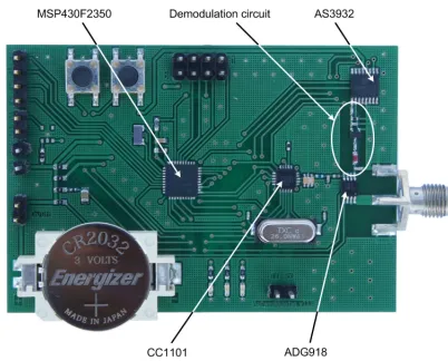
Figure 1. Photo of the assembled sensor node with wake-up re-ceiver.
new. In Bian et al. (2011) a gateway for connecting ZigBee-based nodes to the Internet is presented. In Zhu et al. (2010) the gateway functionality is realized by a smartphone. An-other example of IP-based WSNs and the additional gate-way can be found in Hong et al. (2010) and Ha et al. (2012). However, in all of these examples, the sensor nodes have a permanent active channel or a duty-cycle-based rendezvous scheme. Therefore, a long lifetime in addition to permanent accessibility is not achieved.
The paper is organized in the following way. Section 2 gives a short description about the used wireless sensor nodes that can be targeted by the SmartGate. Section 3 explains the concept and the motivation of the SmartGate. In Sect. 3.1 the server system behind the SmartGate is introduced. Section 3.2 gives information about the hardware and software of the gateway. In Sect. 3.3 the wake-up signal, which is sent by the gateway, is explained. Measurements of the communication range and the current consumption can be found in Sect. 4, followed by the final conclusion.
2 Sensor node with wake-up receiver
The used sensor nodes with wake-up receiver that can be tar-geted by the SmartGate are presented and described in detail in Gamm et al. (2012). They feature a current consumption of 2.8µA in standby mode and a sensitivity for a wake-up signal of −53.6 dBm resulting in a wake-up range of 47 m. To every node a 16-bit address can be assigned that enables a selective wake-up. In this case, the address information has to be integrated in the wake-up signal. Figure 1 shows a picture of the used nodes. An overview about existing wake-up tech-nologies and their benefits can be found in Demirkol et al. (2009).
Request Reply
SmartGate Wake-Up 868 MHz
Sensor data Server-UI/
Frontend Server
User
Internet
SmartGate
Nodes Server
2.4 GH
z 868
M Hz
Figure 2.Whole system overview.
3 SmartGate concept
In comparison to the sensor nodes, the SmartGate is not re-quired to be battery-powered. It can be placed at any point inside a building where a wired power supply is available. The optimum position for the gateway would be in the center of the wireless sensor network, so that the distance to every node is equal (assuming the same attenuation in all direc-tions). For the communication with the nodes, the gateway uses the CC430F5137 system on chip in combination with the CC1190 RF front end (both from Texas Instruments). For the communication with the server, the gateway uses a WiFly RN-131C from Roving Networks. As the server we currently use a Shuttle XS35V2 personal computer with an integrated Intel NM10 Chipset for tethered and untethered communi-cation. For better communication an external 2.4 GHz half dipole omnidirectional antenna instead of the printed circuit board (PCB) antenna was used. The communication concept can be seen in Fig. 2.
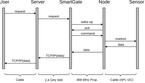
A user from any point in the world can open a website with a graphical user interface for controlling the nodes. The web-site is hosted on the server that has a cable connection to the Internet. If the user requests the status of a node (e.g., inside a building), a TCP/IP packet will be sent to the server. The server spans a private Wi-Fi network inside the building and forwards the request to the SmartGate. The gateway extracts the command and the ID of the requested node and builds up a wake-up signal with the included node ID and sends it out. The woken up node will first turn on its main radio and will send back an acknowledgement to the SmartGate. The SmartGate will then send a message with the user’s request. That can be the readout of a sensor or the control of an actu-ator. The node will accomplish the command and will send back the sensor data or the actuator status to the SmartGate. The SmartGate will send the message back to the server PC, and from there it will find the way back to the user via the Internet. A structured diagram of the message chain can be found in Fig. 3.
G. U. Gamm et al.: SmartGate – connecting wireless sensor nodes to the Internet 47
User Server SmartGate Node Sensor
request
request
wake-up ack command
readout data data
TCP/IP(data) TCP/IP(data)
Cable 2.4 GHz Wifi 868 MHz Prop. Cable (SPI, I2C)
Figure 3.Command chain of the system.
Internet. The domain within the house from the server to the SmartGate uses a secured Wi-Fi network working at 2.4 GHz. The domain from SmartGate to the nodes uses the 868 MHz ISM (industrial, scientific, and medical) band with a proprietary protocol. In this domain two kind of pack-ages are sent: first, the wake-up packpack-ages consisting of the 125 kHz signal modulated on the 868 MHz carrier with in-cluded node ID and, second, normal data packages using GFSK modulation and data handling mechanism. The do-main between node and sensor is dominated by cable con-nection with protocols like SPI or I2C.
3.1 Server
As a server a Shuttle XS35V2 personal computer running on Ubuntu 12.04 LTS is used. It connects to the Internet via Eth-ernet and works as an Wi-Fi access point by spanning a Wi-Fi network with hostapd1. Additionally, an Apache web server was used in combination with PHP 5.3 to provide both the user interface and the control software. The user interface is programmed with modern technologies such as HTML5 and JavaScript to provide access from normal desktop clients as well as from mobile clients such as smartphones or tablets. The control software is built entirely with PHP 5.3, which is a good choice regarding easiness of development as well as portability of the code. It consists of two parts: one part for the interaction with the client like evaluating given arguments and returning final data, and one for the communication with the SmartGate. Due to its architecture, it is possible to sep-arate the two parts to allow direct access for other systems apart from the currently implemented user interface. An ex-ample would be to provide autonomous control by external systems. The current control software would then be used as a simple filter to regulate the access to the gateway, which should not be reachable directly from the Internet for secu-rity reasons. It is possible to integrate the server directly onto the SmartGate by using a tiny embedded web server. Since there might be more than one SmartGate installed in a
build-1http://w1.fi/hostapd/
Server receives request for data
Select gateway based on lookup
tables Multiple gateways in
use?
Wait for data, close connection after
receiving Connect to
gateway, transmit node‐id
and command
Return data
Yes
No
Figure 4.Flowchart of the server software.
ing, we did stick to the concept of only one central server and one or more SmartGates communicating with it. A simplified flow chart of the server software can be seen in Fig. 4.
3.2 Gateway
WiFly receives data by WiFi
WiFly echoes data over UART to CC430
CC430 wakes up due to UART; checks incoming
data
Data complete and valid?
Send wake‐up‐
signal; listen for incoming data; time
out after 300 ms
Return any received data
Put CC430 into standby; WiFly waits for new data No
Yes
Figure 5.Flowchart of the gateway software.
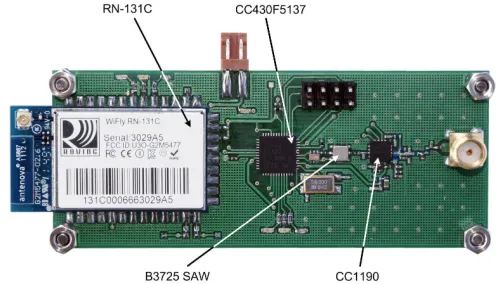
Figure 6.Photo of the assembled SmartGate.
is safe to assume that the node is offline. Either way, the gate-way will close the connection afterwards, therefore telling the server that the transmission has finished. Figure 5 shows a flowchart of the gateway software.
The SmartGate is built on a 1 mm FR4 substrate. Be-sides the RN-131C Wi-Fi module and the CC430F5137, the board incorporates the CC1190 radio fronted from Texas Instruments. It allows increasing the sending power up to +20 dBm, which results in a higher wake-up and commu-nication range. Additional elements on the board are status light-emitting diodes (LEDs) for the Wi-Fi module and the CC430, a 26 MHz crystal for the radio transceiver, a SAW filter from Epcos to suppress unwanted harmonics, JTAG in-terface and a chip balun from Johanson Technology. A photo of the assembled SmartGate can be seen in Fig. 6.
3.3 Wake-up signal
The expected wake-up signal by the nodes is composed of a carrier burst, preamble and address pattern as can be seen in Fig. 7.
To send out a valid wake-up signal, the SmartGate has to follow several steps. First, the 125 kHz wake-up signal has to be built up whereby the correct 16-bit address
informa-Carrier Burst Preamble Pattern: 0010 1101 0011 0111
Figure 7.Expected wake-up signal by the sensor nodes.
tion has to be integrated. Second, the resulting signal must be modulated on the 868 MHz carrier using OOK (on-off key-ing). And, third, the signal must be sent out using the infi-nite packet length mode of the CC1101 radio to overcome the limiting 64-byte FIFOs. Step one and two can be com-bined in the process of building the wake-up packet. Send-ing out a byte of 0xAA (binary 10101010) with a data rate of 250 kBit s−1 at a carrier frequency of 868 MHz results in the modulation of two 125 kHz square periods on the carrier. Using this scheme the whole wake-up packet with a length of 402 byte can be built up. The normal FIFO mode of the CC1101 radio only supports packet length up to 64 byte. To send out a packet with a length of 402 byte without interrup-tion, the infinite packet length mode has to be used. It works by filling the FIFO initially with 64 byte. When these bytes are sent, an interruption can be used to monitor the amount of bytes still remaining in the FIFO. If 32 byte are sent, the interruption is triggered and 32 new bytes from the wake-up packet are filled on the fly in the FIFO. Therefore, the end of packet interruption of the CC1101 radio is first triggered when the last 32 byte from the wake-up packet are sent out.
4 Measurements
4.1 Wi-Fi communication range
G. U. Gamm et al.: SmartGate – connecting wireless sensor nodes to the Internet 49
1 2 3 4
5 1 , 9 5 2 , 0 5 2 , 1 1 0 0 1 2 0 1 4 0 1 6 0 1 8 0 2 0 0 2 2 0
C
u
rr
e
n
t
in
m
A
N u m b e r o f s e n s o r n o d e s P r e s e n t e d s y s t e m
T y p i c a l s y s t e m
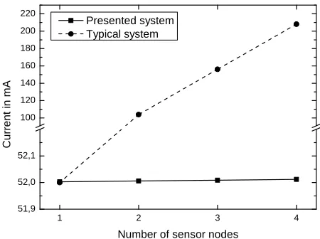
Figure 8.Comparison of a network with Wi-Fi nodes against a network with SmartGate and nodes with wake-up receivers.
antenna to the WiFly module, the communication range was extended up to 290 m.
4.2 Wake-up range
The wake-up range from the SmartGate to a sleeping sen-sor node was done in an open air field. The SmartGate was programmed to send a coded wake-up signal in an infinite loop. One of the sensor nodes was programmed to wake up at the specific address and indicate the wake-up with a blink-ing LED. The SmartGate and the sensor node were mounted on poles of 1.2 m height each and were moved away from each other successively. The blinking, and therefore a posi-tive wake-up, was measured up to a distance of 80 m.
4.3 Current consumption
The current of the devices was measured using a digital mul-timeter 34401A from Agilent. The current consumption of the SmartGate in idle mode was measured to 52 mA, while sending the wake-up signal with active amplifier front end the current was measured to 275 mA. Let us look at a typical small sensor network consisting of four nodes that should be connected to the Internet. Integrating the WiFly mod-ule on every node results in a total current consumption of 220 mA in standby mode. Using four nodes with wake-up receivers and one SmartGate results in a current consump-tion of 52 mA, dominated by the SmartGate. While adding additional nodes to the network will increase the current in a linear way for the typical system, it will add only 2.8µA in the presented system. Figure 8 compares the two systems against each other.
5 Conclusions
The SmartGate can be improved in three major points:
– Security: the CC430F5137 has a built-in AES hardware
accelerator, which would allow fully encrypted commu-nication with the control software of the server and with the sensor nodes. This could prevent attacks from mali-cious devices even when not used in its own Wi-Fi. This is especially important in scenarios where the nodes control actuators (e.g., doors or windows) and where an additional security layer is needed. Furthermore, the RN-131C can be programmed with a password that has to be sent upon any new connection. This would give a first rudimentary protection against attackers. Another possibility for an encrypted communication on the IP-side would be the use of IPsec, which is a protocol suite for a secure IP communication.
– Scalability: while it is possible to use this system in
large-scale environments, it was not explicitly improved for the use in such systems. Applications in this field should implement some kind of routing system for the gateway node communication, which allows the server to talk to a specific node without the need for a lookup table.
– Bidirectional communication: by now, the nodes are
only contacted by the control software of the server. It is possible to change the control software as well as the gateway’s configuration to support communication started by the node, which can be essential in use cases such as burglar alarm systems, where immediate reac-tion is necessary.
The SmartGate provides a practical solution for connecting a wireless sensor network that makes use of wake-up receivers to the Internet. For that task, the gateway can build up a coded wake-up signal with included address information and can send it out with an integrated 868 MHz transceiver. It has the function of a mediator between the Internet with its TCP/IP protocol and the sensor network with its wake-up signals and proprietary data packets. The long wake-up range of 80 m enables a single SmartGate to cover the communication with nodes in a circular area with a diameter of 160 m. The Smart-Gate represents a flexible and effective solution to access a network of wireless sensor nodes with wake-up receivers from the Internet.
Acknowledgements. This work has partly been supported by the German Research Foundation (DFG) within the Research Training Group 1103 (Embedded Microsystems).
References
Atzori, L., Iera, A., and Morabito, G.: The Internet of Things: A survey, Comput. Netw., 54, 2787–2805, doi:10.1016/j.comnet.2010.05.010, 2010.
Bian, J., Fan, D., and Zhang, J.: The new intelligent home control system based on the dynamic and intelligent gateway, in: Broad-band Network and Multimedia Technology (IC-BNMT), 2011 4th IEEE International Conference on, 526–530, 2011.
De Boeck, J.: Game-changing opportunities for wireless personal healthcare and lifestyle, in: Solid-State Circuits Conference Di-gest of Technical Papers (ISSCC), 2011 IEEE International, 15– 21, 2011.
Demirkol, I., Ersoy, C., and Onur, E.: Wake-up receivers for wire-less sensor networks: benefits and challenges, Wirewire-less Commu-nications, IEEE, 16, 88–96, 2009.
Gamm, G. U., Kostic, M., Sippel, M., and Reindl, L. M.: Low-power sensor node with addressable wake-up on-demand capa-bility, Int. J. Sensor Networks, 11, 48–56, 2012.
Ha, M., Kim, S. H., Kim, H., Kwon, K., Giang, N., and Kim, D.: SNAIL gateway: Dual-mode wireless access points for WiFi and IP-based wireless sensor networks in the internet of things, in: Consumer Communications and Networking Confer-ence (CCNC), 2012 IEEE, 169–173, 2012.
Hong, S., Kim, D., Ha, M., Bae, S., Park, S. J., Jung, W., and Kim, J.-E.: SNAIL: an IP-based wireless sensor network approach to the internet of things, Wireless Communications, IEEE, 17, 34– 42, 2010.
Sjoland, H., Anderson, J., Bryant, C., Chandra, R., Edfors, O., Jo-hansson, A., Mazloum, N., Meraji, R., Nilsson, P., Radjen, D., Rodrigues, J., Sherazi, S., and Owall, V.: A Receiver Architec-ture for Devices in Wireless Body Area Networks, Emerging and Selected Topics in Circuits and Systems, IEEE Journal on, 2, 82– 95, 2012.