http://www.sciencepublishinggroup.com/j/ijssn doi: 10.11648/j.ijssn.20190703.12
ISSN: 2329-1796 (Print); ISSN: 2329-1788 (Online)
Design and Simulation of Dual Conversion Transformerless
Online and Line-Interactive UPS
Mahmud-Ul-Tarik Chowdhury
1, Md. Saleh Ebn Sharif
2, *, S. M. Rafiul Islam
2,
Md. Monower Zahid Khan
3, Md. Eliasinul Islam
41
Department of Electrical and Computer Engineering, University Northeastern University, Boston, MA
2Department of Electrical and Electronic Engineering, Bangladesh University of Engineering and Technology, Dhaka, Bangladesh
3Department of Electrical and Electronic Engineering, The University of Manchester, Manchester, UK
4
Department of Electrical, Electronic & Communication Engineering, Military Institute of Science & Technology, Dhaka, Bangladesh
Email address:
*
Corresponding author
To cite this article:
Mahmud-Ul-Tarik Chowdhury, Md. Saleh Ebn Sharif, S. M. Rafiul Islam, Md. Monower Zahid Khan, Md. Eliasinul Islam. Design and Simulation of Dual Conversion Transformerless Online and Line-Interactive UPS. International Journal of Sensors and Sensor Networks. Vol. 7, No. 3, 2019, pp. 44-50. doi: 10.11648/j.ijssn.20190703.12
Received: August 5, 2019; Accepted: August 28, 2019; Published: September 26, 2019
Abstract:
In this paper, a dual-conversion online static UPS and Line-Interactive UPS system were modeled and simulated using PSIM software. The components of the proposed design were specified based on pre-defined constrains, and the dynamic behavior of the system was modeled through state-space equations. With the system components characterized, a suitable controller was developed for closed-loop control of the buck and boost circuits. A battery charge management controller was also developed to ensure the robustness of the design. Overall system performance was analyzed under varying load and line conditions. Both systems consistently supply power to the load regardless of the state of the grid, as long as the battery SOC is adequate.Keywords:
Online UPS, Line-Interactive UPS, PID Controller, Converter Design, Energy Storage1. Introduction
Modern life has created a society dependent on electrical powered devices. For the largest parcel of those equipment applications, such as electronic gadgets, home entertainment systems, electric tools and others, eventual failures in their operation are, at most, inconvenient. On the other hand, for some critical applications, uninterrupted continuous operation is a necessity. The objective behind Uninterruptible Power Supply (UPS) is to guarantee uninterrupted and reliable power delivery to vital loads, meeting minimum power quality standards [1]. Those vital loads, such as medical facilities, life support equipment, data centers and others, are sensitive not only to power outages, but also to several common conditions commonly observed in power grids likeundervoltage, overvoltage, harmonics and transients. UPS systems also protect critical systemsfrom line frequency variation [2]. There are several industries which require continuous power delivery to function properly
oreffectively. Some of those industries, where power failure would carry grievous or expensive consequences, are datacenters, health care, telecommunication, weather forcasting etc. There are also several types of UPS technologies and models. They are mainly divided in (a) Static type UPS and (b) Rotating type UPS. Static type UPS are also divided in (a) Online type (b) Offline type and (c) Line interactive type [5].
is a suitable choice for hybrid energy storage system [14-15]. The similar strategy of energy storage can be also used for renewable integration to grid system.
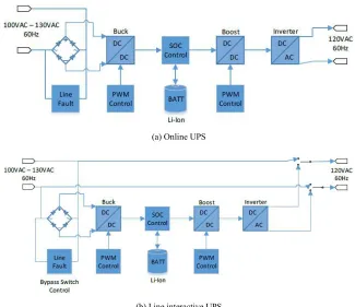
The Online, Offline and Line interactive UPS are shown in figure 1.
Figure 1. Different types of UPS.
Rotating UPS systems store energy in the form of rotational energy. Generally, a flywheel (a rotor with significant rotational kinetic energy storage) is accelerated to a nominal speed. When there is a power outage, the load extracts energy from the flywheel, depleting stored energy [7]. Once the power is restored, the motor regains energy from the grid, accelerating the wheel to its nominal speed. In effect, the flywheel replaces the battery in a traditional system [8]. Due to the differences in conversion process, flywheel systems can be more efficient at lower load levels than static systems [2-3]. There are also other UPS technologies, such - as DRUPS (Diesel Rotary UPS). Emerging technologies using UPS systems to store energy collected through solar power to be used during data center peak times take advantage of smaller sized UPS systems to distribute the storage of energy [4, 13].
In the following subsections, the simulation system modeling of UPSis illustrated in section two. In the third section, the detail buck and boost converter’s PID controller designingis presented.
In fourth section, the detail simulation and result of Online and Line-Interactive UPS are examined respectively.
2. Simulation System Modeling
The design of a dual-conversion online static UPS system was modeled. A simplified diagram of the system is presentedin figure 2 (a). This type of system is an Online UPS system. A better model would include the ability to bypass conversion and leave the system in a standby state when the line power is considered above a predefined quality standard. Having the system in a standby state would improve efficiency, but the quality of the power delivered to the load may not be as good as the Online system ensures. A system with conversion bypass is Line-Interactive. Thesimplified diagram of Line-Interactive type UPS is shown in figure 2(b). These two simplified diagrams of figure 2 are implemented in PSIM for analysis which is discussed on section IV.
(a) Online UPS
(b) Line interactive UPS
3. Converter Modeling
The converter was controlled for the required output power, voltage and current ripples by the PWM varying duty cycle. The block for controlling converter and feedback system for output regulation are shown in figure 3. Where, H(s) is the sensor gain, Gvd(s) is the converter control-to-output transfer function. Gvg(S) is the converter line-to-output transfer function and Gc(s) is the controller gain [9].
Figure 3. Feedback control diagram for converter.
3.1. Buck Converter Modeling
The dynamics of the system components were modeled using the state-space method in order to design PWM controllers for the buck and boost converters. A summary of this analysis is presented here.
Figure 4. Buck Converter Model.
The equations for analyzing the buck converter dynamics is found considering open and close operation of the switch, M. In following euqtions, VL is the voltage across the
inductor and Icis capacitor current.
When switch M is closed:
L in on L out di(t)
V V R I V L
dt
= − − =
( ) ( )
o u t o u t
L V t d V t
Ic I C
R d t
= − =
When M is Closed:
( ) ( )
L d o u t d i t
V V V t L
d t
= − − =
( ) ( )
o u t o u t
L V t d V t
Ic I C
R d t
= − =
Then, the state space model of these equations has applied and transfer function of the system was calculated from the the state space model:
1
( ) ( )
G s =C sI−A− Bu+Du
_
2
( )
1 1
[ ( ) ( )
in m d vout D
m m
V R I V
G S
DR DR
LC s s
L RC RLC LC
− +
=
+ + + +
For the buck converter, the inductor and capacitor values were selected to suit the battery specifications. The selected battery is a 48V, 20Ah, Li-Ion battery with a charge current rating of 25%→5A. So, output of buck converter has to be 48V. Considering an allowable current ripple to be 10%, then ∆i=0.5A. Also, considering an allowable voltage ripple to be 2% results in ∆V=0.96V. Since the input line voltage range is 100Vac -130Vac and the output voltage of the buck converter is 48V, we can consider the nominal output voltage of the rectifier circuit to be 110Vdc and the nominal PWM value (D) to be 0.4363. Assuming a switching frequency of 100kHz, the inductor and capacitor values were chosen to be 500uH and 100uF respectively. Also, for the MOSFET, Rm =
50 mohm, and the diode, Vd = 0.7 V. With the buck converter
parameters defined, the plant transfer functionis shown in below. The design specifications and parameters are shown in table 1.
_
8 2 5
120 ( )
(5 10 ) (5.302 10 ) 1
vout D G S s s − − = × + × +
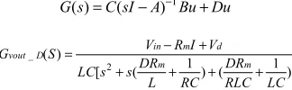
Figure 5. Bode Plot of transfunction, Gvout_D.
Table 1. Design Specification.
Parameters Buck Converter Boost Converter
Input voltage, Vin 110Vdc (Nominal) 48Vdc
Output voltage, Vout 48Vdc 160Vdc
Current ripple, ∆i 10% 10%
Voltage ripple, ∆V 2% 2%
Switching Frequency, fs 100KHz 100Khz
Capacitor, C 100uF 50uF
Inductor, L 500uH 200uH
Energy Storage
Battery voltage (Li-ion) 48V @ 20Ah
Initial SOC 0.5
The bode plot of transfunction, Gvout_D is plotted on figure
5. It is found that the phase margin isvery low, so it can be said the transferfunction is marginally stable, hence there is a need for designing a PID controller. With the configured PID controller the combined transfer function is shown below. The corresponding bode plot of plant is shown in figure 6. From figure 6, it is seen that the phase margin is good enough to make the converter stable.
2 4 8
8 4 3 2 5
1.47 (3.149 10 ) 1.206 10 ( )
(5 10 ) 0.01168 13.33 (2.325 10 )
s X s X
G S
X − s s s X s
+ +
=
+ + +
Figure 6. Bode Plot of Buck Converter Plant.
3.2. Boost Converter Modeling
A Boost converter is modelled using same fashion. The correspondingequation of boost converter is found when switch, M is closed and open.
Figure 7. Boost Converter Model.
When switch, M is closed:
L
L in m L di (t)
V V R I L
dt
= − =
( ) ( )
o u t c
V t d V t
Ic C
R d t
= − =
When switch, M is open:
( )
( ) L
L in d o u t d i t
V V V V t L
d t
= − − =
( ) out L V t
Ic I
R = −
( ) out L V t Ic I
R
= − Ic IL Vout( )t
R
= −
After applying state space model the corresponding transfer function of Gvout_D of Boost converter is
_ 2 1 ' ( )( ) ( )( ) ( ) 1 ' ( ) ( )
m m d out
vout D
m m
R D IR V V D s
L C L C
G S
DR D R D s s
L RC RLC LC
− + +
+ − +
=
+ + + +
Selecting the values of L and C to balance minimizing ripple with producing an acceptable transfer function, the values selected are L=200uH and C=50uF. As with the buck converter analysis, Rm = 50 mohm, and Vd = 0.7V. The Boost converter is
not stable and phase margin was not adequate. To stabilize the system, a PID controller was configured to compensate the plant transfer function in the same fashion as with the buck converter. However, stability of the boost converter control proved to be inadequate during switching of Line-interactive UPS. For this reason, the boost converter was run in the open-loop mode for the Line-Interactive version of the system in this project. The reason behind boost converter’s open loop operation and its solution are discussed on section IV.
4. Schematic and Simulation Results
Simulations were divided into two separate models: Online and Line-Interactive. Testing consisted of varying the line voltage level while simultaneously monitoring buck converter operation, battery SOC, and boost converter operation. Results for the online system are presented first. The simulations are done in PSIM. The simplified diagram of online and line-interactive UPS in figures 2(a) & 2(b) are implemented in PSIM.
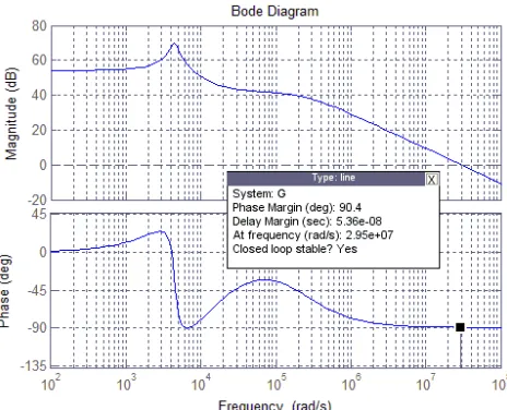
4.1. Online UPS Simulation
(a) Line Voltage vs Battery SOC Plots
(b) Load Voltage, Grid Voltage and Battery Voltage Plots
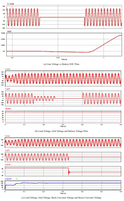
(c) Load Voltage, Grid Voltage, Buck Converter Voltage and Boost Converter Voltage
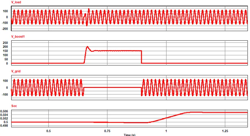
4.2. Line-Interactive UPS Simulation
The Line-Interactive version of the model was also simulated. However, results of this system were not as favorable. Stability of the boost converter control proved to be inadequate during switching. For this reason, the boost converter was run in the open-loop mode for the Line-Interactive version of the system in this project. It is suspected that phase difference between the grid volage and inverter output was causing large currents during bypass switching events. In order to avoid this situation a PLL (Phase-Lock-Loop) circuit could be employed to ensure synchronization between the inverter output and the gridvoltage. It was beyond the scope of this project. However, it will be investigated in the second part of this project.
To simulate the Line-Interactive version without losing stability of the boost converter, closed-loop control of the boost converter was removed. With the boost converter operating open-loop, the following results are obtained. Figure 9 (a) shows the response of the system when the grid voltage is lost. The buck converter stops to work and the boost converter starts supplying the load and the battery SOC begins to deplete. Figure 9(b) further illustrates system operation. When the grid voltage is lost, the battery SOC is decreasing. Later, when the grid voltage is restored, the battery SOC increases until it reaches a limit set by the battery SOC controller.
(a) Load Voltage, Battery Voltage, Buck Converter Voltage, Boost Converter Voltage, and Battery SOC
(b) Load Voltage, Boost Converter Voltage, Grid Voltage and Battery SOC
5. Conclusions and Future Work
Simulations of the Online UPS system and the Line-Interactive UPS system presented very promising results. The PID controllers configured for the PWM control of the boost and buck converters restore stability to the subsystems and regulate the load voltage and battery charge respectively. Both systems consistently supply power to the load regardless of the state of the grid, as long as the battery SOC is adequate. It is suspected that phase difference between the grid volage and inverter output of Line-Interactive UPS was causing large currents during bypass switching events. In order to avoid this situation, a PLL (Phase-Lock-Loop) circuit should be employed to ensure synchronization between the inverter output and the gridvoltage. The detailed analysis of isolated high frequency transformerless/ transformer-based UPS system for small energy storage can be done as future work of this project.
References
[1] S. Bekiarov, and A. Emadi, “Uninterruptible power supplies: classification, operation, dynamics, and control,” 17th IEEE Applied Power Electronics Conference Proceedings, Dallas, TX, March2002, pp. 597–604.
[2] M. Milad, and M. Darwish, UPS system: How can future technology and topology improve the energy efficiency in data centers? IEEE Power Engineering Conference (UPEC), 2014 49th International Universities, Cluj-Napoca, 2-5 Sept. 2014, pp. 1-4.
[3] M. Milad, and M. Darwish, Comparison between Double Conversion Online UPS and Flywheel UPS technologies in terms of efficiency and cost in a medium Data Centre, Power Engineering Conference (UPEC), 2015 50th International Universities, Year: 2015, pp. 1–5.
[4] Longjun Liu, Hongbin Sun, Yang Hu, Jingmin Xin, Tao Li, and Nanning Zheng, Leveraging distributed UPS energy for managing solar energy powered data centers, Green Computing Conference (IGCC), 2014 International, Year: 2014, pp. 1-8.
[5] Rasmussen, Neil, “The Different Types of UPS Systems, Whitepaper (1) Revision 7”, APC white paper, Schneider Electric.
[6] Aamir, Muhammad, WajahatUllah Khan Tareen, Kafeel Ahmed Kalwar, Mudasir Ahmed Memon and SaadMekhilef. “A High-Frequency Isolated Online Uninterruptible Power Supply (UPS) System with Small Battery Bank for Low Power Applications.” (2017).
[7] E. Blondel and C. Monney, "Efficient powering of communication and IT equipments using rotating UPS," 4th International Telecommunication - Energy special conference, Vienna, Austria, 2009, pp. 1-5.
[8] Carl Cottuli, “Comparison of Static and Rotary UPS”, Whitepaper (92), APC white paper, Schneider Electric.
[9] Chowdhury, Mahmud-Ul-Tarik, Sharif, Md Saleh Ebn, “Design and Analysis of a Isolated SiC MOSFET based full-bridge DC-DC converter” 5th International Conference on Development of Renewable Energy Technology 2018 (ICDRET’18), Kathmandu, Nepal, 2018.
[10] H. S. Khalil, S. A. Shehata, M. A. El-Bakry and A. E. M. M. Aly, "Modeling and simulating an UPS system with feedforward and feedback control," IECEC-97 Proceedings of the Thirty-Second Intersociety Energy Conversion Engineering Conference (Cat. No. 97CH6203), Honolulu, HI, 1997, pp. 1732-1737 vol. 3.
[11] W. Solter, "A new international UPS classification by IEC 62040-3," 24th Annual International Telecommunications Energy Conference, 2002, pp. 541-545.
[12] Taeck-Kie Lee, Woo-Cheol Lee, Hoon Jang and Dong-Seok Hyun, "A study on the line-interactive UPS using the series voltage compensator," IEEE 2002 28th Annual Conference of the Industrial Electronics Society. IECON 02, 2002, pp. 733-738 vol. 1.
[13] Milad, M., and M. Darwish. "UPS system: How can future technology and topology improve the energy efficiency in data centers?" In Power Engineering Conference (UPEC), 2014 49th International Universities, pp. 1-4. IEEE, 2014.
[14] Iftikhar, M., Aamir, M., Waqar, A., Muslim, F. B. and Alam, I., 2018. Line-Interactive Transformerless Uninterruptible Power Supply (UPS) with a Fuel Cell as the Primary Source. Energies, 11 (3), p. 542.