R E S E A R C H
Open Access
A parallel camera image signal processor
for SIMD architecture
Seung-Hyun Choi
1, Junguk Cho
2, Yong-Min Tai
2and Seong-Won Lee
1*Abstract
An image signal processor (ISP) for a camera image sensor consists of many complicated functions; in this paper, a full chain of the ISP functions for smart devices is presented. Each function in the proposed ISP full chain is designed to handle high-quality images. Every function in the chain is fully converted to a fixed-point arithmetic, and a special function is not used for easy porting to a Samsung Reconfigurable Processor (SRP). Several parallelizing optimization techniques are applied to the proposed ISP full chain for real-time operation on a given 600-MHz reconfigurable processor. To verify the performance of the proposed ISP full chain, a series of tests was performed, and all of the measured values satisfy the quality and performance requirements.
Keywords:CMOS image sensor, Image signal processor, Reconfigurable processor, Parallel processing optimization
1 Introduction
Image sensors are used in numerous types of image acquisition devices such as digital cameras, camcorders, and CCTV cameras. Recently, their application region has broadened to include smart devices, and the acquired images are not merely for storage but also for interaction between a human and a computer. To satisfy the many goals of image sensors, the role of image enhancement is more important than ever before.
An image signal processor (ISP) is one of the non-op-tical devices that enhance the image quality of captured raw images and consists of several image processing algorithms including demosaicing, denoising, and white balancing, as well as other image enhancement algo-rithms. The latest ISP algorithms that include iterations with adaptive selections according to the image charac-teristics produce an excellent image quality. The high image quality costs vast amount of calculation, however, and also require complicated adaptive routines that cannot be executed in parallel.
An ISP can be implemented on a dedicated hardware, a general-purpose processor, or a parallel-computing
processor. A dedicated hardware implementation,
however, shows a high image quality and processing
performance at the expense of scalability and flexibility, whereas the implementation of an ISP on a general-purpose processor can be appropriate not only for the high image quality of complicated algorithms, but also for sound scalability and flexibility; however, the imple-mentation cost of the latter is high due to the large com-putational amount, and a high-performance platform such as a desktop PC is necessary. The high processing performance and low power consumption of a parallel-computing processor are accompanied by scalability and flexibility for software implementation. The implemen-tation of an ISP algorithm on a parallel-computing pro-cessor, however, requires further optimization for the utilization of multiple processing elements in parallel. The conventional parallel-ISP-optimization methodology requires the division of the algorithm into data processing parts and control processing parts first, followed by their operation in parallel because of the adaptivity of the ISP algorithm. Very Long Instruction Words (VLIW) architecture can therefore be an easy choice for ISP im-plementation, even though Single Instruction Multiple Data (SIMD) architecture can exploit a greater extent of parallelism.
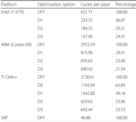
The ISP full chain that is suitable for parallel processing is proposed in this paper, and the chain is implemented through an optimization process for SIMD processor archi-tecture to achieve both a high image quality and perform-ance goals. The proposed ISP full chain is shown in Fig. 1.
* Correspondence:[email protected]
1Department of Computer Engineering, Kwangwoon University, 20,
Kwangwoon-ro, Nowon-gu, Seoul, Republic of Korea
Full list of author information is available at the end of the article
In Fig. 1, GWA is Gray World Assumption, AHD is Adaptive Homogeneity-Directed Demosaicing, BF is Bi-lateral Filter, AC is Auto Contrast, and LTI is Luminance Transient Improvement.
The way that the high-quality images are processed by all of the algorithms that are present in the proposed ISP chain means that there are no iterations in the algo-rithm to reduce the execution time of the real-time budget [1]. While the basic idea of the algorithm is maintained, the operations in the algorithm have been simplified for easy parallelization on the SIMD architec-ture; in addition, heavy memory accesses and excessive computational overheads are reduced by limiting the op-erational ranges. Each complicated special operation is replaced by a simple operation that performs a similar function and the result was verified by experiments.
The proposed parallel ISP algorithm is targeted to run
on the Samsung Reconfigurable Processor (SRP) [2–7]
that can be configured as an SIMD processor. Numerous high-quality image processing algorithms form the basis of each of the functional components of the proposed ISP full chain [8–30]. By increasing the homogeneity of
the parallel operations in the ISP algorithms, the proposed ISP algorithm can take advantage of the parallel perform-ance of a SIMD processor while maintaining an image quality that can pass the commercial image quality test of Skype [31]. The proposed ISP can handle the resolution of full HD video (1920 × 1080, 30 frames per second) on a 600-MHz SRP that is suitable for smart devices.
This paper comprises the following: Section 2 describes the existing research; Section 3 describes the implemen-tation of the proposed ISP full chain; Section 4 describes the performance verification process and the results of the proposed ISP full chain; and the conclusion is presented in Section 5.
2 Background research
2.1 Algorithms of the ISP full chain
The functions of the ISP full chain mainly support re-covering non-existing pixels, noise reduction, and image enhancement. The proposed ISP full chain consists of white balancing, demosaicing, color correction, color space conversion, denoising, detail enhancement, and gamma correction.
Color interpolation
(Modified AHD) White Balance
(GWA)
Color Correction
Noise Reduction (Modified BF)
Gamma Correction Detail
Enhancement (Modified LTI)
Color Conversion (RGB to YCoCg)
Color Conversion (YCoCg to RGB)
10 bits Bayer pattern
10 bits Bayer pattern
8 bits Red, Green,
Blue 8 bits Y
8 bits Co, Cg
10 bits Red, Green,
Blue
The color images that enter through an image sensor can show colors that are different to those that are seen by the naked eye; to correct this, the White Balance (WB) process can be used. The WB algorithm GWA [8, 9] assumes that the average of the image is gray; similarly, the white-patch Retinex (WR) algorithm [10] assumes that the maximum-intensity pixel is white. Since these as-sumptions can be statistically false, Iterative White Balan-cing (IWB) [11] iteratively refines the white pixels while illuminant voting [12] checks the lighting conditions. The GWA is chosen for the proposed ISP, since it allows for an optimal parallelization during implementation that is due to a relatively structured computation compared with the existing algorithms, as follows:
CWBðx;yÞ ¼C xð ;yÞ
Xn x
Xn y
RþX
n x
Xn y
GþX
n x Xn y B !
=3X
n x
Xn y
C
ð1Þ
where Crepresents one of R, G, and B andCWB
repre-sents the color value after white balancing.
After the WB process, demosaicing is an algorithm for the production of full RGB channels, which is achieved by the interpolation of the color pixels that are lacking in image sensor-captured images. Many algorithms including heuristic methods, directional interpolations, frequency domain approaches, wavelet-based methods,
and reconstruction approaches [13–16] exist; in this
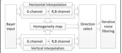
study, Adaptive Homogeneity-Directed Demosaicing (AHD) [15], a type of directional interpolation method that is commonly used for digital still cameras, was modified and used. A higher image quality is associated with other algorithms like wavelet-based methods [16], but they are not suitable for real-time implementation on the reconfigurable processor that is used in this study due to the huge amounts of calculations and iterations. The rough flowchart of the AHD algorithm is shown in Fig. 2.
The directional interpolation of the AHD performs interpolation in the direction of the strongest edge that flows either vertically or horizontally. Finding the direc-tion of the edge depends on the homogeneity of the
neighboring pixels that will also be generated. The homogeneity map is defined by Eq. (2), as follows:
Hfððx;yÞ;δ;εL;εCÞ ¼
B xðð ;yÞ;δÞ∩Lfððx;yÞ;εLÞ∩Cfððx;yÞ;εCÞ
B xðð ;yÞ;δÞ
j j
ð2Þ
B xðð ;yÞ;δÞ ¼fp∈XjdXððx;yÞ;pÞ≤δg ð3Þ
Lfððx;yÞ;εLÞ ¼fp∈XjdLðf xð ;yÞ;f pð ÞÞ≤εLg ð4Þ
Cfððx;yÞ;εCÞ ¼fp∈XjdCðf xð ;yÞ;f pð ÞÞ≤εCg ð5Þ
where Bis a set of the δdistance from (x,y)∈X; X is a set of 2D pixel positions; Bis defined by Eq. (3);Lfand
Cfare in the neighborhood that is established by the
dis-tance of the luminance and color in the CIELab color space and are defined by Eqs. (4) and (5), respectively; E is a set of tolerance values and δ,εL,εC∈E; and dL and
dC are distance functions, where luminance and the ab
plane in the CIELab color space are used. A detailed implementation of AHD is introduced in Hirakawa and Parks [15].
Inevitably, the acquired images comprise a variety of noises due to the characteristics of the sensor and
con-verter circuits that are used—especially with the low
light of an indoor environment. To remove these noises effectively, highly adaptive noise reduction methods such as the Bilateral Filter (BF) [18–21] or a 3D noise reduction filter [22, 23] can be used. The BF, proposed by Aurch et al. [20] and improved by Tomash et al. [21], is a non-linear adaptive low-pass filter with vari-able weighting factors according to the distance and the intensity of the neighboring pixels. Equation (6) shows the BF:
BF xp;yp
¼ 1
W xp;yp
X
xq;yq∈S
GS xp;yp
− xq;yq
GI I xp;yp
−I xq;yq
I xp;yp
ð6Þ
where the normalization term W(xp,yp) is defined in
Eq. (7):
W xp;yp
¼ X
xp;yp∈S
GS xp;yp
− xq;yq
GI I xp;yp
−I xq;yq
ð7Þ
In Eqs. (6) and (7), (xp,yp) is the location of the center
pixel, (xq,yq) is the location of the neighboring pixel
I(xp,yp), I(xq,yq) represents the intensities of the
corre-sponding pixels, GS is the Gaussian function for the
spatial domain, and GIis the Gaussian function for the
intensity domain. The proposed ISP uses a modified BF
that can flatten the noise area while preserving the edge information.
For an improved subjective image quality, it is neces-sary to enhance the contrast and edge information; to improve the image contrast, auto level, AC, and histo-gram equalization are examples of the methods that can be used [24]. The proposed ISP full chain includes the AC function that comprises a relatively low color dis-tortion and less complex operations; in addition, Lumi-nance Transient Improvement (LTI) and ChromiLumi-nance Transient Improvement (CTI) are also applied to enhance the edges of the luminance and chrominance, respectively [25, 26]. For LTI and CTI implementation, the difference of Gaussian method [27] is used because of the relatively simple corresponding operations and an excellent edge extraction performance. The differ-ence of Gaussian method is represented by Eq. (8):
O xð ;yÞ ¼I xð ;yÞ þ 1 2πσ2e
−x2þy2 2σ2
ððg1−g2Þ X xð ;yÞÞ ð8Þ
whereOis the enhanced signal,Iis the input luminance signal,g1andg2are two Gaussian filters with the variances
σ1andσ2, the symbol“∗” is the 2D convolution operator,
xis the row number, andyis the column number.
The color correction function changes an entire color according to the desired color temperature. In the proposed ISP full chain, color correction is combined with color conversion to reduce the redundant memory accesses. The applied color correction matrix is shown in Eq. (9), as follows:
Rcc Gcc Bcc 2 4
3 5¼½CC
R G B
2 4
3
5¼ CCgrrr CCrgggCCrbgb Cbr Cbg Cbb 2
4
3 5 GR
B
2 4
3 5 ð9Þ
where Crr through to Cbb are the correcting values that
will be multiplied by the RGB channels andRcc,Gcc, and
Bccare the color-corrected values of the color channels.
While the acquired images are processed in the ISP full chain, several different color spaces are used. Color conversion is a signal-processing technique for the transformation of the color representation coordinates into another coordinate system where some of the color axes comprise a small correlation, and the application of signal-processing functions can reduce the incidence of processing errors [30]. In the proposed ISP, the input signal is initially in the RGB space before it is converted
into the YCoCg color space, and the input is then
sub-jected to luminance-related processes; subsequently, the signal is converted back to the RGB space, color-related processes are applied to the signal, and the signal is then sent to the output display.
Co¼R−B ð10Þ
Cg ¼G−BþðCo>>1Þ ð11Þ
Y¼BþðCo>>1Þ þ Cg >>1
ð12Þ
where Y, Co,Cg, and R, G, Bare the pixel values of the
YCoCgcolor space and the RGB color space.
Gamma correction (GC) modifies the linearity of the camera input to match the non-linearity of the human visual system [28, 29]. If GC is not applied to the ac-quired images, humans cannot differentiate the immense number of bits that represent the information. The GC can be modeled as Eq. (13); in the proposed ISP, the GC is implemented using a polynomial approximation:
I0ðx;yÞ ¼AI xð ;yÞγ ð13Þ
where I' is output image, I is input image, and γ is gamma value.Ais a constant 1 in a common case.
2.2 Implementation platform
The proposed ISP is implemented on an SRP in accord-ance with the test of the preliminary version of the pro-posed ISP [1]. Since the SRP can support both of the parallel processing modes SIMD and VLIW, the proposed ISP is accelerated by the implementation of numerous key operations so that it can run in parallel. The SRP supports the following three operation modes: SIMD, VLIW, and scalar. As the SRP configuration that is used in this study can process 128 bits at a time with 16 functional units, it supports SIMD configurations that can process four 32-bit, eight 16-bit, or 16 8-bit data at the one time. In the VLIW mode, eight of the function units can be operational at the same time, whereby up to eight operations can be executed in parallel. Since the routing channel of the SRP comprises independent configurations for the SIMD, VLIW, and sca-lar modes, the three modes cannot be used in combination; however, the SRP can switch among the three operational modes dynamically while the ISP software is processed. While the sequential codes in the complex control se-quences of the algorithm run in Scalar mode, the parallel codes of the massive image data processing operation are accelerated in the SIMD mode or the VLIW mode.
The memory access of the SRP should be aligned by 128-bit words; therefore, if the data size is not a 128-bit word, the data should have an additional buffering stage to ensure an alignment with the 128-bit words. The SRP also consists of a single memory port for read-and-write operations; therefore, memory-intensive jobs like lookup table operations cannot be parallelized and they signifi-cantly slow down the processing speed.
in this mode. The control operations often limit the parallelism, however, because of the dependency among the codes and data; alternatively, the SRP often suffers from the lack of data that is processed in parallel in the SIMD mode. Since a lack of parallelism is inherent to the algorithm, the algorithms in the proposed ISP are modified to supply enough parallelism; therefore, the proposed ISP can mostly run in the SIMD mode for a sufficient computational performance. Figure 3 shows the SRP architecture overview.
In Fig. 3, FU is Function Unit, RF is Register Files, VLIW is Very Long Instruction Words, and CGRA is Coarse Grained Reconfigurable Array.
The existing research shows that other algorithms that have been ported on the SRP platform such as the ray-tracing algorithm [4] comprise low-power audio pro-cessing [5] and 3D graphics [6]. The proposed ISP full chain is designed to work with SIMD-style parallel processing; however, due to its high parallelism, the proposed design can be used for platforms with other types of microprocessors such as Intel [31], ARM [32], and the TI Digital Signal Processor (DSP) [33].
Intel processors and ARM processors are based on the superscalar architecture that executes multiple instructions at the same time. The performances of the Intel processor platforms are more effective that those of the ARM processor platforms because the former contains a variety of hardware accelerators for multimedia processing (MMX, SSE, etc.); alterna-tively, ARM processor platforms consume less power than Intel processor platforms, making them suitable for mobile applications. TI DSP platforms comprise VLIW architectures, whereby multiple signal-processing
operations and control operations can be executed in parallel.
2.3 Algorithm porting on SRP
A number of optimization technologies were used to improve the computational performance of the ISP full chain on the SRP while the image quality is maintained. The SRP that is used in this study comprises several commands for the efficient use of SIMD arithmetic data. The composition of the SIMD commands is for the processing of the 128-bit data of eight 16-bit data. The SIMD commands are composed of ADD, SHF (shift), CLIP, MUL (multiply) and ADD, and MUL and SHF functions. Since there is no SIMD command to verify the results after the comparison, the SUB and CLIP commands were used in combination so that the results after the comparison could be available for implemen-tation. The SIMD commands were heavily used in the proposed ISP functions for a high performance.
3 Module optimization for the proposed ISP
3.1 WB
In the proposed ISP, the WB uses the GWA algorithm [9]. The GWA algorithm corrects the colors of an image, assuming that the average color of each RGB channel is gray. Using Eqs. (14) to (16), we calculated the GWA as follows:
Rgain¼
RþGþB
3R ð14Þ
Ggain¼
RþGþB
3G ð15Þ
Bgain¼
RþGþB
3B ð16Þ
whereRgain,Ggain, andBgainare the color gain values for
each of the channels andR,G, andBare the averages of the pixel values of the corresponding color channels.
In the input Bayer pattern, the number of G pixels is twice those of the R or B pixels. As the WB process requires the average of the entire image, it is possible to use the data of only half of the G pixels without incur-ring a significant error; therefore, when the GWA was applied, only half of the G pixels were used so that the GWA equaled the calculation amounts of R and B. Since the sum of the entire pixel amount is too large to fit into an integer register, a proper significant figure addition was used to limit the bit number of the sum. If the size of the integer registers that are used for the calculations is too small, the effective numbers become too small while the errors become larger; contrarily, if the integer register size is too large, the processor limitation makes parallelization difficult. For this reason, the sum register size was limited to 32-bit and the temporary variables can be stored in the 64-bit registers. Since the SRP does not support division, shift operations are used for the WB result. A division by 3 in Eqs. (14) to (16) is simpli-fied by 3/8, which is performed as a multiplication by 3 followed by a shift right by three bits.
3.2 Modified AHD
As in Fig. 2, after the WB process is performed in the Bayer pattern of the image sensor, the modified version of the original AHD [15] is used as a demosaicing algo-rithm. The AHD consists of the following three steps: directed interpolation, homogeneity-directed map cre-ation, and iterative noise filtering. The method for finding the direction of the edge is dependent upon the location and color of the pixel that is to be generated. The width of the variables is 16 bits including three bits for the fractional part. An operational example of the proposed modified AHD is explained in the following section.
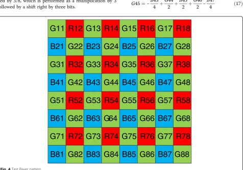
In Fig. 4, R, G, and B are the red, green, and blue pixels, respectively, and the number is the pixel position. Figure 4 comprises GBRG, the Bayer pattern of the image sensor that was used for the proposed ISP imple-mentation; based on G44 in the middle, GBRG is com-posed of a pattern that consists of G44, B45, R54, and G55, and numbering starts from the top left. Equations (17) and (18) represent the horizontal interpolation of the G and R pixels on the B channel where the input B pixel exists. In Eqs. (17) to (27), all of the parameters are the corresponding pixel values of the locations in Fig. 4.
G45¼−B43
4 þ
G44
2 þ
B45
2 þ
G46
2 −
B47
4 ð17Þ
G11 R12 G13 R14 G15 R16 G17 R18
B21 G22 B23 G24 B25 G26 B27 G28
G31 R32 G33 R34 G35 R36 G37 R38
B41 G42 B43 G44 B45 G46 B47 G48
G51 R52 G53 R54 G55 R56 G57 R58
B61 G62 B63 G64 B65 G66 B67 G68
G71 R72 G73 R74 G75 R76 G77 R78
B81 G82 B83 G84 B85 G86 B87 G88
R45¼R34 4 þ R36 4 þ R54 4 þ R56
4 ð18Þ
Equations (19) and (20) represent the horizontal interpolation of the G and B pixels on the R channel where the input R pixel exists, as follows:
G54¼−R52
4 þ G53 2 þ R54 2 þ G55 2 − R56
4 ð19Þ
B54¼B43
4 þ B45 4 þ B63 4 þ B65
4 ð20Þ
Equations (21) to (24) represent the horizontal interpolation of the R and B pixels on the G channel where the input G pixel exists, as follows:
R44¼R34
2 þ
R54
2 ð21Þ
R55¼R54
2 þ
R56
2 ð22Þ
B44¼B43
2 þ
B45
2 ð23Þ
B45¼B45
2 þ
B65
2 ð24Þ
The original AHD repeats the calculation vertically, and it also comprises an additional direction-selection process after the generation of the homogeneity map ac-cording to the calculation of the CIELab color conversion and epsilon parameter. The modified AHD selects the direction immediately after the interpolation of the G channel, and then the R and B channels are interpolated only once; by doing this, the process of selecting a direction-based RGB pixel value is removed to reduce the amount of calculation. The G channel interpolation equation is also modified, as shown in Eqs. (25) to (27):
H¼abs B25
2 þ
B65 2 −B45
ð25Þ
V¼abs B43
2 þ
B47 2 −B45
ð26Þ
G45¼ B44
2 þ
B46 2 ðH≥VÞ B35
2 þ
B55
2 ðH <VÞ
8 > < >
: ð27Þ
where H is horizontal direction weight, V is vertical direction weight, and abs() is absolute value function. In Eqs. (25) and (26), and using Eq. (27), the G channel interpolation depends on the results that are obtained by the horizontal and vertical direction calculations of the three tap filters.
An iterative noise filtering is used in the original AHD. The iterative noise filtering is removed for the reduction
of operational loads, however, and it is also a redundant operation because it is performed by the modified BF in the next stage.
To minimize the data load for the Bayer pattern images in the modified AHD, the memory area is desig-nated a size that is one column larger than the original image size and the images are read only once. By ma-nipulating the pointer to the start position, boundary processing is not needed at the time of the RGB channel interpolation, and an ordered data loading technique is applied to the vertical filter that is used for the RGB channel interpolation.
When data are loaded from the memory and fed into a filter, some of the data load may be overlapped due to the convolution operation of the filter. The pseudo codes 1 and 2 show the pseudo codes of the data load for horizontal loading and vertical loading, respectively, for the 1 × 3 filter. As shown in pseudo code 1, the buf-fer size is 128 bits; that is, it consists of eight 16-bit data. Once the filtering of an image line is complete, the filtering of the next image line loads a new image line (at code line 8) and the two lines that had been loaded while the previous image line was processed (code lines 6 and 7 are shown at code lines 2 and 3, respectively). To prevent such an overlapping of data loading, the data should be loaded by row unit, and then the required data should only be read by referring to the existing buffer, as shown in pseudo code 2, where the overlapped data load in pseudo code 1 does not exist. This technique, as shown below, is used for modi-fied AHD, modimodi-fied BF, modimodi-fied LTI, and other modules in the proposed ISP.
Pseudo code 1: line i:
1: Buf1[0:127] = Image[i-1,j + 0:127] 2: Buf2[0:127] = Image [i,j + 0:127] 3: Buf3[0:127] = Image [i + 1,j + 0:127] 4: OUTPUT[0:127] = C1*Buf1[0:127] +
C2*Buf2[0:127] + C3*Buf3[0:127] 5: j = j + 128; goto 1
line i + 1:
6: Buf1[0:127] = Image[i,y + 0:127] 7: Buf2[0:127] = Image [i + 1,y + 0:127] 8: Buf3[0:127] = Image [i + 2,y + 0:127] 9: OUTPUT[0:127] = C1*Buf1[0:127] +
C2*Buf2[0:127] + C3*Buf3[0:127] 10: j = j + 128; goto 6
Pseudo code 2: Before line i:
1: Buf1[0:127] = Image[i-1,j + 0:127] 2: Buf2[0:127] = Image [i,j + 0:127] line i:
4: OUTPUT[0:127] = C1*Buf1[0:127] + C2*Buf2[0:127] + C3*Buf3[0:127] 5: temp = C1; C1 = C2; C2 = C3; C3 = temp line i + 1:
6: Buf3[0:127] = Image [i + 2,j + 0:127] 7: OUTPUT[0:127] = C1*Buf1[0:127] +
C2*Buf2[0:127] + C3*Buf3[0:127] 8: temp = C1; C1 = C2; C2 = C3; C3 = temp At the bottom of the image:
9: j = j + 128
where C1, C2, and C3 are the filter coefficients in pseudo code 1 and pseudo code 2.
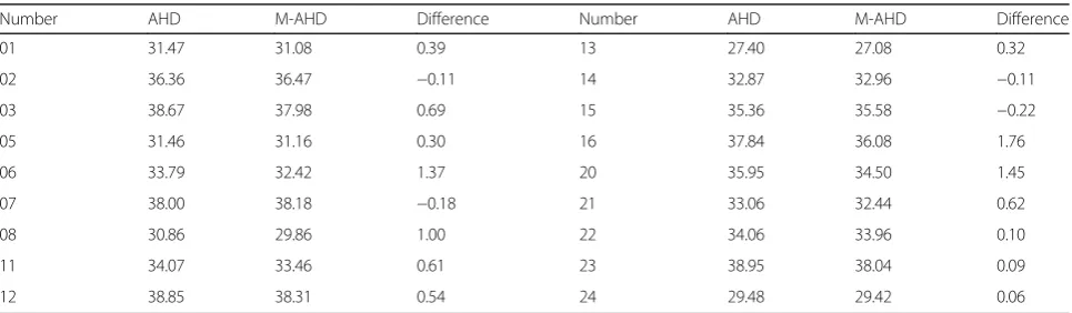
The PSNR values for the modified AHD algorithm are compared with those of the conventional AHD in Table 1. Kodak lossless true color images were modified to form the GBRG Bayer pattern images that are used for the PSNR comparison. The PSNR differences vary
between −0.22 and 1.76 dB, with an average difference
of 0.48 dB, while the computational load is significantly reduced.
3.3 Color correction and color space conversion
After demosaicing, the color correction block finds the color features and repairs the color artifacts; the color correction is processed by the color correction matrix, and the matrix that was used is shown in Eq. (9). The color correction equation can be calculated in conjunc-tion with the subsequent color space conversion. The
proposed ISP, the YCoCg color space, is used because it
has a lower correlation among the color channels com-pared with other color spaces, and it performs integer operations only without any information loss. Because the color correction equation can be combined with the equation of the YCoCgcolor space conversion, the inter-mediate process for the storage of the values of the color correction result can be removed, thereby reducing the memory access cycle. The equations for performing the
combined color correction and the YCoCg color space
conversion are shown in Eqs. (28) to (31):
Bcc ¼CbrRþCbgGþCbbB ð28Þ
Co¼CrrRþCrgGþCrbB−Bcc ð29Þ
Cg ¼CgrRþCggGþCgbB−Bcc
þðCo>>1Þ ð30Þ
Y¼BccþðCo>>1Þ þ Cg >>1
ð31Þ
where Y, Co,Cg, and R, G, Bare the pixel values in the
YCoCgcolor space and RGB color space, respectively. A
color control function is also combined in the YCoCg
color space conversion to control the color saturation and color offset. A coefficient integerization technique was used for the color correction.
3.4 Auto contrast
A linear stretch method is used in the AC, and the linear scale factors in the AC function were calculated in the
YCoCgcolor space. Equations (32) and (33) were applied
to the AC that is used in this study:
RS ¼
Bmax Ymax−Ymin
ð32Þ
Yout¼RSðYin−YminÞ ð33Þ
whereRS is stretch ratio; Bmaxis the maximum value of
bit depth;YmaxandYminare the maximum and minimum
values of the Y channel, respectively; Yin is the input
image; andYoutis the image after AC. For the calculation
of the Ymax and Yminvalues, a technique to separate and
rearrange the algorithm is used to reduce the memory ac-cesses. First, theYmaxandYminvalues were calculated by
using theYvalue that is obtained through the YCoCgcolor
conversion, and the calculated results are used for the AC calculation that is included in the modified BF function. The AC optimization techniques have been designed to shift operations, instead of resulting in the breakage of the coefficient integerization.
Table 1PSNR comparison with AHD and modified AHD (M-AHD)
Number AHD M-AHD Difference Number AHD M-AHD Difference
01 31.47 31.08 0.39 13 27.40 27.08 0.32
02 36.36 36.47 −0.11 14 32.87 32.96 −0.11
03 38.67 37.98 0.69 15 35.36 35.58 −0.22
05 31.46 31.16 0.30 16 37.84 36.08 1.76
06 33.79 32.42 1.37 20 35.95 34.50 1.45
07 38.00 38.18 −0.18 21 33.06 32.44 0.62
08 30.86 29.86 1.00 22 34.06 33.96 0.10
11 34.07 33.46 0.61 23 38.95 38.04 0.09
3.5 Modified BF
BF is used as a noise reduction algorithm [18–21]. The original BF comprises the following two Gaussian filters: one is for the distance weight between pixel locations and the other is for the difference weight between pixel intensities. To simplify these two Gaussian filters, the Gaussian functions are replaced by fixed-point, binary threshold functions in the proposed modified BF. The threshold values are determined by pre-calculating the Gaussian filter coefficients for the pixel locations and pixel intensities.
In the proposed ISP algorithm, the BF is simplified to reduce the amount of calculation. Since the Gaussian
function requires a special math hardware, GS and GI
are replaced by the binarization functionsBSandBI. The
size of the spatial domain of GS in the proposed ISP is
7 × 7. The output ofBSfor the same domain size is 1 for
a 3 × 3 area and 0 for any others; therefore, the domain
S of 7 × 7 is replaced by the new domain S' of 3 × 3.
The BI that is the binarization of GIis represented by
the following:
BI Ip−Iq
¼ 1Ip−Iq≤ITh 0Ip−Iq>ITh 8
<
: ð34Þ
whereITh is the threshold value of the pixel value
dif-ference. The resulting modified BF is Eq. (35):
BFModified½ ¼p 1 W0p
X
q∈S0
BI Ip−Iq
Ip ð35Þ
where the new normalization termW'pis the following:
W0p ¼X
q∈S0
BI Ip−Iq
ð36Þ
To further reduce the calculation complexity, the 3 × 3 filter of the domainS' was replaced by a separable filter that is composed of two 1D filters of the sizes 3 × 1 and 1 × 3; by using this separable filter, the computational complexity of the proposed BF becomesO(n), instead of theO(n2) of the original BF [34].
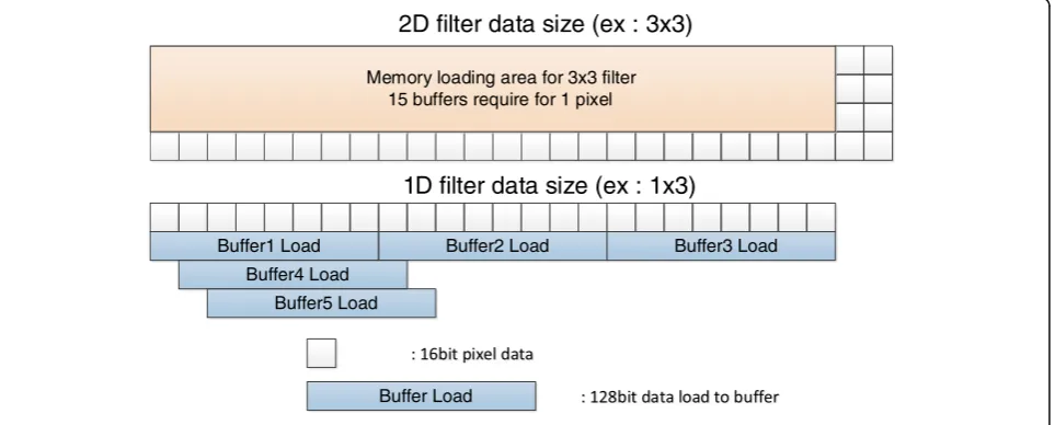
When the algorithm is implemented with a 2D filter, the amount of memory access and computation for the SRP needs to be increased quadratically. Instead of the 2D filters in the original BF, the separable filter is applied to the proposed modified BF. By making the 2D filter separable, the computational load of 2D filtering is reduced to twice that of 1D filtering. Figure 5 compares the filtering operation of a 2D filter with that of a 1D fil-ter for the SRP. Due to the SRP structure, all of the data should be stored in buffers before a filter is used; so, when a 3 × 3 filter mask is used, fifteen 128-bit registers are needed to start a necessary operation. Alternatively, when a 1D filter is used, it is possible to perform an op-eration with five 128-bit registers for a horizontal filter and three 128-bit registers for a vertical filter; therefore, the use of a separable filter also makes it possible to reduce the amount of memory access.
In Fig. 5, a square box represents a single pixel of 16 bits and a buffer has eight-pixel data. In addition, the filter size has also been modified from 7 × 7 to 3 × 1 and 1 × 3, and a vertical data loading technique is applied to the 1 × 3 vertical filter.
3.6 Detail enhancement
For detail enhancement, an LTI based on the difference of Gaussian [27] is used. The Gaussian mask sizes in the
Buffer1 Load Buffer2 Load Buffer3 Load
Memory loading area for 3x3 filter 15 buffers require for 1 pixel
2D filter data size (ex : 3x3)
1D filter data size (ex : 1x3)
Buffer4 Load Buffer5 Load
Buffer Load
LTI are 3 × 3 and 5 × 5, which are with pre-calculated coefficients. Since CTI rarely affects image quality, a simple 1 × 3 Laplacian sharpening filter is configured for the CTI. The separable filters are implemented for LTI and the filter size is adjusted. As the filter that is used here is also a vertical filter, a vertical data loading technique was applied.
3.7 Gamma correction
For GC, the lookup table method or a piecewise linear interpolation method [29] is used. The input data is used as the index of the lookup table method, while the input range and the linear interpolation parameter are checked from the table for the piecewise linear interpolation method. In this study, instead of using the lookup table that is difficult to parallelize due to a large volume of irregular memory access, the quadratic approximation of the GC equation that utilizes the 128-bit data processing of the SRP was used. Equation (37) is the equation that is used for GC:
y¼k1x2þk2xþk3 ð37Þ
where k1, k2, and k3 are the GC coefficients, x is the
pixel value of the RGB channel, and y is the GC result value. The parameters are determined to have the least square error over most of the central region. Since GC is performed for all three of the RGB channels, the algo-rithm was rearranged to use the results of the YCoCg
-to-RGB color space conversion.
4 Experiment results
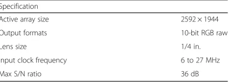
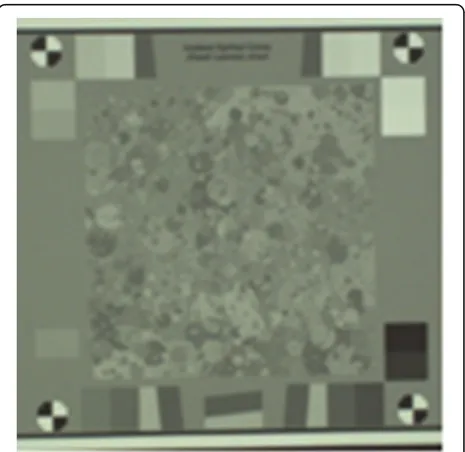
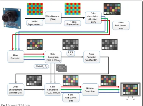
To verify the performance of the proposed ISP full chain, the quality of the result images should first pass a commercially available image quality test such as Skype [35]. The experiments were conducted using a CMOS image sensor with a specification that is shown in Table 2. Figures 6, 7, and 8 are the parts of the test patterns.
Figure 6 is the image quality resolution test pattern, which is used to measure the clearness of luminance im-ages. Figure 7 is for the evaluation of color performance and Fig. 8 is for the verification of texture acuity. Other patterns for the measurement of aspects such as expos-ure error, gamma, SNR, and dynamic range exist.
Table 3 shows the results of the image quality for the proposed ISP full chain that was implemented on the SRP; as shown in Table 3, all of the measured values meet the requirements of the test. Since the entire pro-posed ISP chain has been designed only with fixed-point addition and multiplication, the proposed ISP chain can be easily ported onto any other microprocessor; further-more, even when the characteristics of a CMOS image sensor change, it is still possible to meet the image quality evaluation standards by simply adjusting the coefficients that are used for the ISP full chain.
The performance goal of the proposed ISP is the pro-cessing of full HD image sequences (1920 × 1080, 30 frames per second) with a 600-MHz SRP.
Table 4 shows the number of clock cycles that were taken by the modules in the proposed ISP full chain. The number of cycles for sequential processing com-prises the cycles that are taken without the use of any SIMD operations, and the number of cycles for parallel processing is the cycles that are taken from the use of the SIMD operations of eight processing elements. The parallelizing speedup by a factor of 4.9 is obtained by dividing the total sequential-cycle number by the total parallel-cycle number. The degree of parallelism can be found by using Amdahl’s law of Eq. (38), as follows:
Speedup¼ TsoldþTpold
Tsnew þTpnew
ð38Þ
where Ts_old is the time taken by the sequential
opera-tions that are not affected by parallelization;Tp_oldis the
time taken by the sequential operations that are affected by parallelization;Ts_newis the time taken by the
sequen-tial operations that are not affected by parallelization after improvement; and Tp_new is the time taken by the
parallel operations after improvement.
Since the sequential parts are not affected by parallelization, the processing time does not change after improvement, as shown by Ts_old=Ts_new=Ts. In
the proposed ISP, the parallelization is performed by
the SIMD with eight processing elements, so Tp_new=
Tp_old/8. IfTp_newis assumed as 1, Eq. (38) is changed, as shown in Eq. (39):
4:9¼ðTsþ8Þ Tsþ1
ð Þ ð39Þ
By inducing the sequential timeTs from Eq (39),Ts=
Ts_old= 0.81. Since the total execution time before
parallelization is Ts_old+Tp_old=Ts+Tp_new* 8 = 8.81, the time that is not affected by parallelization is only 9 % of the total sequential execution time, whereby 91 % of the total sequential time is parallelized by the eight processing elements.
Table 2Units and corresponding symbols
Specification
Active array size 2592 × 1944
Output formats 10-bit RGB raw
Lens size 1/4 in.
Input clock frequency 6 to 27 MHz
Since the resolution of the CMOS image sensor that is used in the experiment is larger than that of the target performance, the conversion to get the performances of the full HD image sequences is shown in Eq. (40), as follows:
Cs¼CPPRes¼
Cf
T PRes
¼ 49;080;019
2;6241;956
ð1920108030Þ
¼594;868;812 ð40Þ
where Cs is cycles per second, CPP is cycles per pixels,
Res is target resolution,Cf is simulation cycles, and TP
is the number of test image pixels. Since the input reso-lution of the test camera is 2624 × 1956, the total num-ber of cycles to handle an image of a 1920 × 1080 resolution was recalculated; therefore, the SRP simula-tion result satisfies the real-time operasimula-tion of the target for the 600-MHz SRP.
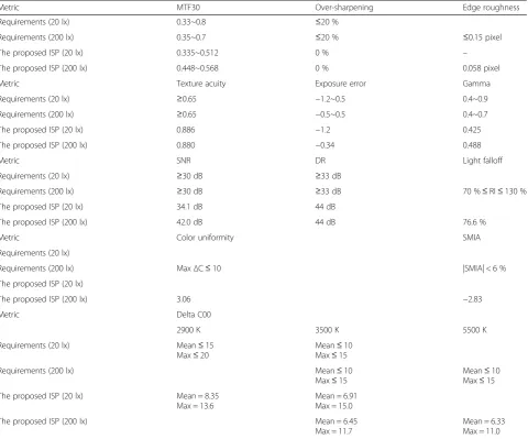
Table 5 shows the performances of the proposed ISP on other platforms in cycles per pixel. To compare the parallelization performances of the proposed ISP algo-rithm in a test, widely used, commercial processor plat-forms were used to run the proposed ISP full chain. For the test platform, general-purpose desktop processors of the Intel processor family, a general-purpose mobile processor of the ARM Cortex family, and a signal-processing VLIW processor of the TI DSP family were chosen; for the TI platform and the SRP platform, the simulators that were provided by the manufacturers were used in the experiments. Since each platform comprises a different operating frequency, the cycles per pixel were calculated for the purpose of comparison. The proposed ISP full chain was compiled for a single
Fig. 6The image quality resolution test pattern
processor because the communication overhead for mul-tiple threads can abuse the efficiency of parallel opera-tions. All of the platforms comprise the multiple-issue pipelines and multimedia instructions of the SIMD style [36–38], and the optimization options were disabled for comparison purpose because the SRC compiler does not have optimization options.
For faster porting, the cycle-accurate simulators for the TI C64x + and SRP were used. The operating fre-quencies of the commercial TI C64x + processors are between 500 and 1200 MHz; for the proposed algo-rithm, the target platform of the SRP processor was designed to run at 600 MHz.
The results in Table 6 show the values of cycles per pixels obtained by using the compiler optimization option along with the proposed ISP full chain. In the case of SRP platform, the SRP compiler does not provide optimization options.
Table 3Image quality test requirements [40] and experiment results
Metric MTF30 Over-sharpening Edge roughness
Requirements (20 lx) 0.33~0.8 ≤20 %
Requirements (200 lx) 0.35~0.7 ≤20 % ≤0.15 pixel
The proposed ISP (20 lx) 0.335~0.512 0 % –
The proposed ISP (200 lx) 0.448~0.568 0 % 0.058 pixel
Metric Texture acuity Exposure error Gamma
Requirements (20 lx) ≥0.65 −1.2~0.5 0.4~0.9
Requirements (200 lx) ≥0.65 −0.5~0.5 0.4~0.7
The proposed ISP (20 lx) 0.886 −1.2 0.425
The proposed ISP (200 lx) 0.880 −0.34 0.488
Metric SNR DR Light falloff
Requirements (20 lx) ≥30 dB ≥33 dB
Requirements (200 lx) ≥30 dB ≥33 dB 70 %≤RI≤130 %
The proposed ISP (20 lx) 34.1 dB 44 dB
The proposed ISP (200 lx) 42.0 dB 44 dB 76.6 %
Metric Color uniformity SMIA
Requirements (20 lx)
Requirements (200 lx) MaxΔC≤10 |SMIA| < 6 %
The proposed ISP (20 lx)
The proposed ISP (200 lx) 3.06 −2.83
Metric Delta C00
2900 K 3500 K 5500 K
Requirements (20 lx) Mean≤15 Max≤20
Mean≤10 Max≤15
Requirements (200 lx) Mean≤10
Max≤15
Mean≤10 Max≤15
The proposed ISP (20 lx) Mean = 8.35 Max = 13.6
Mean = 6.91 Max = 15.0
The proposed ISP (200 lx) Mean = 6.45
Max = 11.7
Mean = 6.33 Max = 11.0
Table 4The number of clock cycles to process one frame with
an SRP simulator
Module Sequential Parallel
WB 11,892,670 2,651,547
Modified AHD 45,935,860 12,695,570
Color correction/RGB to YCoCg/Ymin,max 45,555,149 10,265,334
Modified BF (3 × 1)/AC 46,810,082 5,946,081
Modified BF (1 × 3) 30,112,720 5,154,872
Modified LTI (1 × 3) 21,785,128 3,220,328
YCoCgto RGB/GC 38,521,495 9,146,287
Using GCC compiler, for Intel and ARM platform, option O1 allows for branch, register, and tree optimization. Similarly option O2 (default option in GCC) allows align, local, and global optimization, while option O3 allows all the abovementioned optimization for O1 and O2 along with the parallelizing optimization for loop unrolling and loop vectorization. Although the use of option O3 does not guarantee speedup as com-pared to the use of option O2 [39], the application of optimization option O3 along with the proposed ISP full chain achieves higher speedup due to the inherent higher degree of parallelism.
The TI platform also allows the use of optimization options for the TI compiler. Option O1 in the TI compiler is used for register usage optimization, option O2 is used for global optimization including parallelizing optimization such as software pipelining, loop optimization, and loop unrolling, and option 3 is used for optimization related with inline calls to small functions and reorder function declarations. Again, using the optimization option O2 along with the proposed ISP full chain
achieves higher speedup compared to other options due to higher degree of parallels.
Since the SRP can process eight 16-bit operations in parallel with a single SIMD instruction, the SRP outper-forms the fastest commercial platform i7 by 3.36 times at the fully optimized version in Table 6. Although Intel platforms comprise an issue width of 4 and 4 × 16-bit data SIMD instructions, the inefficiency of the dy-namic scheduling and a lower memory bandwidth limit exploit the parallelism of the proposed rithm; that is, the parallelism of the proposed algo-rithm can also work for Intel platforms. With respect to the ARM platform, its issue width is half that of the Intel platform and it comprises an even lower memory bandwidth, so the cycle-per-pixel value is 4.07 times higher than those of the Intel platforms. The TI platform also comprises two issue pipelines, but there are more operation slots for control opera-tions; however, the proposed algorithm is designed for data parallelism, and the performance gain over the ARM platform is marginal.
5 Conclusions
In this study, a parallel version of the ISP full chain is proposed and implemented on an SRP architecture with eight data width SIMD instructions. The proposed ISP full chain is written in C language for portability, and the image quality was verified with a commercially available test suite. The proposed algorithm was modified for lesser computational loads and a capability that facilitates the easy exploitation of parallelism. A variety of optimization techniques were also applied to make the algorithm suitable for an SIMD-style architecture. The experiment results satisfy both the image quality standard and the real-time operation speed for a 600-MHz SRP with full HD image sequences, and it utilizes approximately five out of the eight operation slots in the SIMD instruction of the SRP. The parallelism of the proposed algorithm was also tested in a comparison with other commercial platforms, and the results show that it can be easily exploited.
Table 5ISP performance comparisons on a variety of platforms
Platform Core used Cycles per pixel Frequency Issue width 16-bit processing elements in SIMD
Intel i7-3770 1 631.71 1.7 GHz 4 4
Intel i5-2500 1 677.14 1.7 GHz 4 4
Intel i3-530 1 1094.77 1.73 GHz 4 4
ARM (Cortex-A9) 1 2972.59 667 MHz 2 1a
TI C64x+ 1 2730.61 Simulation 2 VLIW
SRP 1 46.88 Simulation 1 8
a
Cortex-A9 has SIMD instructions that can handle four 16-bit data, but its C compiler does not support the SIMD instruction set
Table 6Compiler optimization option comparison
Platform Optimization option Cycles per pixel Percentage
Intel i7-3770 OFF 631.71 100.00
O1 233.55 36.97
O2 184.55 29.21
O3 157.40 24.91
ARM (Cortex-A9) OFF 2972.59 100.00
O1 875.90 29.47
O2 695.65 23.40
O3 640.42 21.54
TI C64x+ OFF 2730.61 100.00
O0 1743.09 63.83
O1 1342.80 49.18
O2 629.65 23.06
O3 642.44 23.53
Acknowledgements
This research was partly supported by Samsung Electronics; the MSIP (Ministry of Science, ICT and Future Planning), Korea, under the ITRC (Information Technology Research Center) support program (IITP-2016-H8501-16-1005) supervised by the IITP (Institute for Information and Communications Technology Promotion), and the Research Grant of Kwangwoon University in 2015.
Authors’contributions
SC implemented the proposed ISP algorithm, participated in its whole experiments, and drafted the manuscript. JC and YT provided the guides on the performance requirements and the design of experiments and gave the feedbacks on the experimental results. SL conceived of the study and participated in its design and coordination and helped to draft the manuscript. All authors read and approved the final manuscript.
Competing interests
The authors declare that they have no competing interests.
Author details
1Department of Computer Engineering, Kwangwoon University, 20,
Kwangwoon-ro, Nowon-gu, Seoul, Republic of Korea.2DMC R&D Center,
Samsung Electronics Co.,LTD, 129, Samsung-ro, Yeongtong-gu, Suwon-si, Gyeonggi-do, Republic of Korea.
Received: 12 May 2015 Accepted: 21 September 2016
References
1. S Choi, J Cho, Y Tai, S Lee, Implementation of an image signal processor for reconfigurable processor, 2014 IEEE International Conference on Consumer Electronics, (IEEE, Las Vegas, NV, 2014), pp. 141–142
2. D Suh, K Kwon, S Kim, S Ryu, J Kim, Design space exploration and implementation of a high performance and low area coarse grained reconfigurable processor, 2012 International Conference on Field-Programmable Technology, (IEEE, Seoul, Korea, 2012), pp.67-70 3. Y Cho, S Jeong, J Jeong, H Shim, Y Han, S Ryu, J Kim, Case study:
verification framework of Samsung reconfigurable processor, 2012 13th International Workshop on Microprocessor Test and Verification, (IEEE, Austin, TX, 2012), pp.19-23
4. J Lee, Y Shin, W Lee, S Yun, J Kim, Real-time ray tracing on coarse-grained reconfigurable processor, 2013 International Conference on Field-Programmable Technology, (IEEE, Kyoto, Japan, 2013), pp.192-197 5. S Jin, W Seo, Y Cho, S Ryu, Low-power reconfigurable audio processor
for mobile devices, 2014 IEEE International Conference on Consumer Electronics, (IEEE, Las Vegas, NV, 2014), pp.369-370
6. K Kwon, S Son, J Park, J Park, S Woo, S Jung, S Ryu, Mobile GPU shader processor based on non-blocking coarse grained reconfigurable arrays architecture, 2013 International Conference on Field-Programmable Technology, (IEEE, Kyoto, Japan, 2013), pp.198-205
7. NR Miniskar, PS Gode, S Kohli, D Yoo, Function inlining and loop unrolling for loop acceleration in reconfigurable processors, Proceedings of the 2012 international conference on Compilers, architectures and synthesis for embedded systems, (ACM, New York, NY, 2012), pp. 101–110
8. RC Bilcu, Multiframe auto white balance. IEEE Signal Process. Lett.18(3), 165–168 (2011)
9. J Huo, Y Chang, J Wang, X Wei, Robust automatic white balance algorithm using gray color points in images. IEEE Trans. Consum. Electron.52(2), 541–546 (2006) 10. N Kehtarnavaz, H Oh, Y Yoo, Development and real-time implementation of auto
white balancing scoring algorithm. J. Real-Time Image Proc.8(5), 379–386 (2002) 11. C Weng, H Chen, C Fuh, A novel automatic white balance method for
digital still cameras, IEEE International Symposium on Circuits and Systems, (IEEE, Kobe, Japan, 2005), pp. 3801–3804.
12. G Sapiro, Color and illuminant voting. IEEE Trans. Pattern Anal. Mach. Intell.
21(11), 1210–1215 (2002)
13. BK Gunturk, J Glotzbach, Y Altunbasak, RW Schafer, RM Mersereau, Demosaicking: color filter array interpolation. IEEE Signal Process. Mag.22(1), 44–54 (2005) 14. D Menon, G Calvagno, Color image demosaicking: an overview. Signal Process.
Image Commun.26(8–9), 518–533 (2011)
15. K Hirakawa, TW Parks, Adaptive homogeneity-directed demosaicing algorithm. IEEE Trans. Image Process.14(3), 360–369 (2005)
16. BK Gunturk, Y Altunbasak, RM Mersereau, Color plane interpolation using alternating projections. IEEE Trans. Image Process.11(9), 997–1013 (2002) 17. M Fairchild, Color appearance models, 2nd edn. (John Wiley & Sons, New
York, NY, USA, 2005)
18. S Paris, F Durand, A fast approximation of the bilateral filter using a signal processing approach, 9th European Conference on Computer Vision, (Springer, Graz, Austria, 2006), pp. 566–580
19. T Melange, M Nachtegael, EE Kerre, Fuzzy random impulse noise removal from color image sequences. IEEE Trans. Image Process.20(4), 959–970 (2010) 20. V Aurich, J Weule, Non-linear Gaussian filters performing edge preserving
diffusion, 17th DAGM-Symposium Mustererkennung, (Springer-Verlag London, Bielefeld, Germany, 1995), pp.538-545
21. S Paris, P Kornprobst, J Tumblin, F Durand, Bilateral filtering: theory and applications, (Now Publishers Inc, Boston, MA, USA, (2009)
22. O Ghita, DE Ilea, PF Whelan, Adaptive noise removal approach for restoration of digital images corrupted by multimodal noise. IET Image Process.
6(8), 1148–1160 (2012)
23. R Manduchi, C Tomasi, Bilateral filtering for gray and color images, Sixth International Conference on Computer Vision, (IEEE, Bombay, India, 1998), pp. 839–846
24. N Sengee, A Sengee, H Choi, Image contrast enhancement using bi-histogram equalization with neighborhood metrics. IEEE Trans. Consum. Electron.
56(4), 2727–2734 (2010)
25. T Kim, J Paik, Adaptive contrast enhancement using gain-controllable clipped histogram equalization. IEEE Trans. Consum. Electron.54(4), 2803–2810 (2008) 26. J Cho, J Bae, Color transient improvement with transient detection and
variable length nonlinear filtering. IEEE Trans. Consum. Electron.54(4), 1873–1879 (2008)
27. Y Wang, X Chen, H Han, S Peng, Video luminance transient improvement using difference-of-Gaussian, 15th Asia-Pacific Conference on Communications, (IEEE, Shanghai, China, 2009), pp.249-253
28. GGC Holst, TS Lomheim, CMOS/CCD sensors and camera systems, 2nd edn, (SPIE, Bellingham, WA, 2007)
29. ES Kim, SW Jang, SH Lee, TY Jung, KI Sohng, Optima piece linear segments of gamma correction for CMOS image sensor, IEICE Trans. Electron, 88-C(11), 2090-2093(2005)
30. B Pham, G Pringle, Color correction for an image sequence, IEEE Comput. Graph. Appl. Mag., 15(3), 38-42(1995)
31. HW Certification Team, Skype hardware certification specification for all Skype video devices version 5.0, http://www.imatest.com/wp-content/ uploads/2011/11/Skype_cert-desktop-api-spec-video_5.0.pdf, accessed 15 Jan 2013
32. JP Shen, MH Lipasti, Modern processor design fundamentals of superscalar processors, (Waveland Press Inc, Illinois, 2013)
33. S Furber,ARM system-on-chip architecture, 2nd edn. (Addison-Wesley, Boston, 2000)
34. N Seshan, High VelociTI processing [Texas Instruments VLIW DSP architecture], IEEE Signal Process. Mag., 15(2), 86–101,117(1998)
35. F Porikli, Constant time O(1) bilateral filtering, 2008 IEEE Conference on Computer Vision and Pattern Recognition, (IEEE, Anchorage, AK, 2008), pp. 1–8 36. D Levinthal, Performance analysis guide for Intel® Core™i7 processor and
Intel® Xeon™5500 processors, https://software.intel.com/en-us/articles/ processor-specific-performance-analysis-papers, accessed 15 March 2015 37. Technical Reference Manual, Cortex-A9 MPCore, https://developer.arm.com/
products/processors/cortex-a/cortex-a9 , accessed 15 Mar 2015
38. SPRU732J, TMS320C64xC64x + DSP CPU and instruction set, http://www.ti.com/ lit/ug/spru732j/spru732j.pdf, accessed 15 March 2015
39. K Hoste, L Eeckhout, Cole: compiler optimization level exploration, Proceedings of the 6th annual IEEE/ACM international symposium on Code generation and optimization, (IEEE/ACM, New York, NY, USA, 2008), pp.165-174
![Fig. 3 SRP architecture overview [3]](https://thumb-us.123doks.com/thumbv2/123dok_us/896365.1587158/5.595.60.543.432.720/fig-srp-architecture-overview.webp)