Power-Electronics-based Energy Management
System with Storage
Sujata B. Girawale
Electronics and Telecommunication Dept.G.H.R.C.E.M. Ahmednagar, Maharashtra, India
Abstract-In Today’s world energy management system is most important. Power electronics based energy management system used here The EMS includes batteries and a digitally controlled single-phase voltage source inverter (VSI), which can be controlled as a current source or a voltage source depending on the status of the ac grid and the user’s preference. The EMS guarantees that the critical loads are powered when the ac grid fails; in which case, the VSI is controlled as a voltage source. It also accomplishes peak power control by supplying battery power to the local loads while they are powered by the ac grid if the loads get large. The electricity cost savings done by peak shaving are estimated.
Keywords – EMS, Peak power control, Cost saving, Peak shaving, islanding mode etc.
I. INTRODUCTION
Energy savings and energy efficiency have become top priorities all around the world, stimulated by the Kyoto protocol and other pressing needs to reduce fossil fuel consumption [1]. Additionally, energy security is a necessity for many installations such as military bases and health care facilities where reducing energy consumption must be accomplished while keeping critical electrical loads serviced at all times. In this paper, A Power-electronics-based energy management system (EMS) is presented to accomplish peak power control in a single-phase power system while guaranteeing continuous service to critical loads at the same time. Peak power control, also known as peak shaving [2], is a method used to reduce the electricity charges for users with time of use (TOU) contracts and those who pay for the demand charges [1]. The power system does not need to be a micro-grid, meaning that distributed generation (DG) does not need to be part of the power system [4].
II. OBJECTIVE
Objective of This system is
1) Peak shaving by tapping the energy storage system during high power demand.
2) Islanding or standalone mode of operation when the main AC grid is no longer available. 3) Battery charging mode.
III. ARCHITECTUREOVERVIEW
Fig 1 EMS Architecture [5]
The EMS functionality is demonstrated in this paper by experimental validation with a laboratory prototype. The following scenarios are discussed:
1) Peak shaving by tapping the energy storage system during high power demand
2) Islanding or stand-alone mode of operation when the main ac grid is no longer available; 3) Battery charging mode.
In power electronics based energy management system when ac grid is not available, at that time critical load are powered through battery charging.
4.1 Explanation:
The FPGA can be used to implement any logic function. The Spartan 6 family of Field-Programmable Gate Arrays is specifically designed to meet the needs of high volume, cost-sensitive consumer electronic applications.
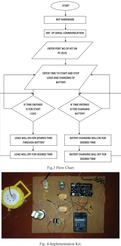
The interfacing unit consists of FPGA kit, relays, battery, inverter, load, and transformer. For controlling the energy management PC is used as a controlling unit. From PC we send commands to switch relays, these relays are interfaced with a inverter through which load is operated. A battery is connected to the inverter in order to provide supply to load. Transformer is used to charge the battery. The inverter converts dc supply to ac supply.
4.2 Inverter
A power inverter, or inverter, is an electronic device circuitry that changes direct current (DC) to alternating current (AC).Power inverter device or circuit requires a relatively stable DC power source capable of supplying enough current for the intended power demands of the system. Here we used a fully transistorized inverter that can drive up to 60W loads.
4.3 Relay:
A relay is an electrically operated switch. Current flowing through the coil of the relay creates a magnetic field which attracts a lever and changes the switch contacts. The coil current can be on or off so relays have two switch positions and they are double throw (changeover) switches. Relays allow one circuit to switch a second circuit which can be completely separate from the first.
START
INIT HARDWARE
INIT OF SERIAL COMMUNICATION
ENTER PORT NO OF KIT ON PC (GUI)
ENTER TIME TO START AND STOP LOAD AND CHARGING OF
BATTERY
IF TIME ENTERED IS FOR START
LOAD
LOAD WILL ON FOR DESIRED TIME THROUGH BATTERY
IF TIME ENTERED IS FOR CHARGING
BATTERY
BATERY CHARGING WILL ON FOR DESIRED TIME
LOAD WILL OFF FOR DESIRED TIME BATERY CHARGING WILL OFF FOR DESIRED TIME
Fig.3 Flow Chart
Fig .4-Implementation Kit:
VI. RESULT
A. Peak Shaving and Battery Charging With the AC Grid Connected
Fig.4 Peak shaving with the EMS providing some of the load current from the battery pack when the load increases [5].
Peak shaving is achieved by controlling the RMS current in the load, which is related to the source current. A threshold is set for the load current, such that when the load RMS current exceeds this threshold; the EMS supplies some of the load current. This keeps the peak current drawn from the ac grid below a set limit. In the laboratory experiments presented here, the threshold for the load current is such that the peak shaving feature turns ON when the load current is greater than 2.2 Arms and turns OFF when the load current is below 2.1 Arms[1].
Fig.5 EMS turning ON at t=0to charge the battery pack [5].
The EMS turns ON to charge the battery at t=0 sin Fig.4as demonstrated by the EMS current Iems being 180°out of phase with respect to the ac voltage. Only linear loads are used for this experiment, because the diode rectifier load is disabled. The battery charging mode of operation is allowed because the load is light, so the EMS does not need to provide an additional current for peak shaving.
B. EMS Powering Critical Loads When the AC Grid Fails—Islanding Mode of Operation
Fig.6 Experimental waveforms showing the ac grid being restored at t=0[5]
The disturbance in the voltage waveform is noticeable when the EMS reconnects the ac grid to the loads as shown in Fig.5. There is also an inrush current into the diode rectifier because the dc voltage of the rectifier had sagged some during islanding mode. Note that the ac voltage produced by the EMS during the islanding mode is slightly smaller (about 7%) than the ac grid voltage
VII. OBSERVATIONS
Parameter
Peak shaving
Islanding mode
Battery
operation
ON
(Charging)
ON (discharging)
EMS current
OFF
ON
Load current
Isource
Iems
Table 1. Experimental results
VIII. CONCLUSION
[4] S. Vazquez, S. M. Lukic, E. Galvan, L. G. Franquelo, and J. M. Carrasco, “Energy storage systems for transport and grid applications,”IEEE Trans. Ind. Electron., vol. 57, no. 12, pp. 3881–3895, Dec. 2010.
[5] Power electronics based energy management system,Giovanna Oriti, Senior Member, IEEE, Alexander L. Julian, Member, IEEE, Nathan J. Peck833 Dyer Road, Spanagel 437, Monterey, CA, 93943 - USA
![Fig 1 EMS Architecture [5]](https://thumb-us.123doks.com/thumbv2/123dok_us/1405186.1652786/2.612.129.488.424.687/fig-ems-architecture.webp)
![Fig.6 Experimental waveforms showing the ac grid being restored at t=0[5]](https://thumb-us.123doks.com/thumbv2/123dok_us/1405186.1652786/6.612.160.453.73.221/fig-experimental-waveforms-showing-ac-grid-restored-t.webp)