MEDICAL IMAGE ANALYSIS USING MULTI
RESOLUTION FUSION TECHNIQUES
K.Kalyani1 and P.Bhavani Sankar2
I. INTRODUCTION
With the advent of imaging sensors say in medical applications, the fusion of different images captured from different sources are necessary to develop a meaningful image for proper diagnosis. The captured images can be fused at different levels of information like at signal, pixel, feature, symbolic level, etc. The fusion of images at pixel level proves best for medical image processing. It undergoes the process of developing a composite image from different input images. Other applications where the image fusion is used are the fusion of images from an airborne sensor platform to help a pilot to navigate in poor weather conditions or darkness, i.e., to fuse forward looking infrared (FLIR) and low light visible images (LLTV).
In pixel-level image fusion, the basic constraints are that the fusion process should preserve all relevant information of the input imagery in the composite image called as pattern conservation, it should not introduce any artifacts or inconsistencies which would distract the human observer or following processing stages, the fusion process should be shift and rotational invariant, i.e. the fusion result should not depend on the location or orientation of an object the input imagery, combining out-of-focus images, remote sensing, etc.
But for the case of image sequence fusion, the additional problem of temporal stability and consistency arise. Temporal stability refers to the graylevel changes in the fused sequence caused by graylevel changes in the input sequences which must not be introduced by the fusion scheme. Temporal consistency refers to graylevel changes occurring in the input sequences that must be present in the fused sequence without any delay or contrast change. These are caused due to human visual system which is sensitive to moving light stimuli, so when artifacts move or time depended contrast changes, the fusion process will be highly distracting to the human observer.
1
Assistant Professor, Department of Electronics and Communication Engineering, Aditya College of Engineering and Technology,Surampalem, A.P,India
2
Assistant Professor, Department of Electronics and Communication Engineering Aditya College of Engineering and Technology,Surampalem, A.P,India
DOI: http://dx.doi.org/10.21172/1.82.007
e-ISSN:2278-621X
Abstract: In severe situations like accidents occur, majority of registered cases are for bone or head injury. For proper diagnosis, both CT scan and MRI scan are required to study the damage occurred for skull as well as for the internal organ injury of brain for the development of any brain tumors. If a combination of both images is present in a single image, then diagnosing the patient would be easier. Image Fusion is a method used to combine two input images to generate a combined complementary information contained image. For medical image processing, the resultant image is required to be highly reliable, low cost in terms of storage cost, uncertainty, etc. Also the information in both CT scan and MRI scan must be retained in the fused image for reliable study and assessment for diagnosis. This paper deals with pixel level fusion methods and their generic multiresolution fusion scheme. This scheme utilizes the low pass residuals and high pass residuals to segregate the information of two input images that are to be fused. The linear and nonlinear methods are used to develop the fused image. The fused image is evaluated in terms of fusion metrics such as standard deviation, entropy, fusion mutual information, etc. The methods like laplacian pyramid, ratio pyramid, principal component analysis, average methods prove to be better options for medical image fusion.
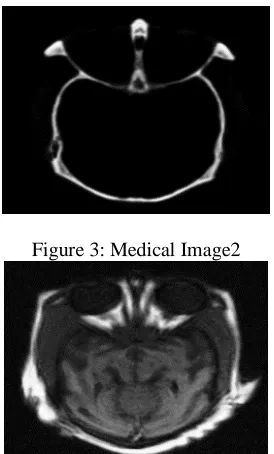
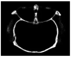
In medical imaging for diagnosis, majorly two scans are used to obtain the essential scan data of disease affected areas. They are CT (Computed Tomography) image and MRI (Magnetic Resonance Imaging) image. In cases where brain related images are to be studied these two images are considered for assessment. If there exists a solution to merge these two details without much loss, it would help doctor to assess the stage of disease correctly and help him to properly diagnose the patient to suggest medication or alternative surgery. The CT scan is used to observe the bone injuries whereas MRI Scan is used to observe the brain tumors. The combination of these two is evaluated for complete brain diagnosis, especially when a person has been injured in an accident.
This paper deals with the methods used for medical image fusion based on pixel level fusion. The metrics used for comparing fused images are standard deviation, entropy, PSNR, SNR and Mutual Information. These metrics prove whether the information in fused image is correct to utilize or not.
II. EXISTING METHODS
There exist several approaches to the pixel level fusion [1-7] of spatially registered input images, majority of them are developed for the fusion of stationary input images. Due to the static nature of the input data, temporal aspects arising in the fusion process of image sequences, e.g. stability and consistency need not addressed. The image fusion methods can comprise of linear superposition, nonlinear methods, optimization approaches, artificial neural networks, image pyramids, wavelet transform, generic multiresolution fusion scheme, etc.
Linear Superposition Method represents the straightforward method to build a fused image of several input frames is performing the fusion as a weighted superposition of all input frames. The optimal weighting coefficients, with respect to information content and redundancy removal, can be determined by a principal component analysis (PCA) of all input intensities. By performing a PCA of the covariance matrix of input intensities, the weightings for each input frame are obtained from the eigenvector corresponding to the largest eigenvalue.
Nonlinear Methods are developed based on simple nonlinear operator such as max or min. If in all input images the bright objects are of interest, a good choice is to compute the fused image by a pixel-by-pixel application of the maximum operator. Basically these use morphological operators such as opening or closing, the actual fusion process is performed by the application of conditional erosion and dilation operators. In high-level algebraic extension of image morphology, the basic types defined in image algebra are value sets, coordinate sets which allow the integration of different resolutions and tessellations, images and templates. For each basic type binary and unary operations are defined which reach from the basic set operations to more complex ones for the operations on images and templates. Image algebra has been used in a generic way to combine multisensor images.
Artificial Neural Networks are used to fuse different sensor signals in biological systems. For example, Rattlesnakes (and the general family of pit vipers) possess so called pit organs which are sensitive to thermal radiation through a dense network of nerve fibers. The output of these pit organs is fed to the optical tectum, where it is combined with the nerve signals obtained from the eyes. Newman and Hartline distinguished six different types of bimodal neurons merging the two signals based on a sophisticated combination of suppression and enhancement.
Optimization Approaches use bayesian optimization problem. Using the multisensor image data and an a-prori model of the fusion result, the goal is to find the fused image which maximizes the a-posteriori probability. Due to the fact that this problem cannot be solved in general, some simplifications are introduced: All input images are modeled as markov random fields to define an energy function which describes the fusion goal. Due to the equivalence of of gibbs random fields and markov random fields, this energy function can be expressed as a sum of so-called clique potentials, where only pixels in a predefined neighborhood affect the actual pixel. The fusion task then consists of a maximization of the energy function. Since this energy function will be non-convex in general, typically stochastic optimization procedures such as simulated annealing or modifications like iterated conditional modes will be used.
There are several modifications of this generic pyramid construction method described above. Some authors propose the computation of nonlinear pyramids, such as the ratio and contrast pyramid, where the multiscale edge representation is computed by a pixel-by-pixel division of neighboring resolutions. A further modification is to substitute the linear filters by morphological nonlinear filters, resulting in the morphological pyramid. Another type of image pyramid - the gradient pyramid - results, if the input image is decomposed into its directional edge representation using directional derivative filters.
Wavelet Transform is a signal analysis method similar to image pyramids, called as discrete wavelet transform. The main difference is that while image pyramids lead to an overcomplete set of transform coefficients, the wavelet transform results in a nonredundant image representation. The discrete 2-dim wavelet transform is computed by the recursive application of lowpass and highpass filters in each direction of the input image (i.e. rows and columns) followed by subsampling. One major drawback of the wavelet transform when applied to image fusion is its well known shift dependency, i.e. a simple shift of the input signal may lead to complete different transform coefficients. This results in inconsistent fused images when invoked in image sequence fusion.
To overcome the shift dependency of the wavelet fusion scheme, the input images must be decomposed into a shift invariant representation. There are several ways to achieve this: The straightforward way is to compute the wavelet transform for all possible circular shifts of the input signal. In this case, not all shifts are necessary and it is possible to develop an efficient computation scheme for the resulting wavelet representation. Another simple approach is to drop the subsampling in the decomposition process and instead modify the filters at each decomposition level, resulting in a highly redundant signal representation.
III. PROPOSED METHODS
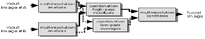
The Generic Multiresolution Fusion Scheme develops a local contrast change i.e., at edges as both image pyramids and the wavelet transform result in a multiresolution edge representation. The input images are decomposed into their multiscale edge representation, using either any image pyramid or any wavelet transform. The multiscale resolute images are combined using the high pass residuals and low pass residuals by using wavelets by the process of pixel-by-pixel selection of the coefficients with maximum magnitude. Finally the fused image is computed by an application of the appropriate reconstruction scheme. The corresponding figure is shown in figure 1.
The metrics used to evaluate the fused image can be based on whether a reference image is available or not. If the reference image is available, the SNR and PSNR can be used. Where SNR is signal to noise ratio and is used to measure the ratio between information and noise of the fused image and PSNR is Peak Signal to Noise Ratio and it represents the number of gray levels in the image divided by the corresponding pixels in the reference and the fused images. The higher values corresponding to these metrics represent the similarity of reference image and fused image and superior fusion of images respectively.
If only the fused image is available then the metrics used for evaluation are Standard deviation, entropy, fusion mutual information, etc. The standard deviation is used to measure the contrast in the fused image, a high value indicates high contrast fused image. Entropy is used to measure the information content of a fused image; a high entropy value indicates the fused image as rich information content. Fusion Mutual Information is used to compute the degree of dependency between the input images and fused image, a large value indicates a better quality of fused image.
IV. RESULTS AND DISCUSSION
The table 1 shows the corresponding metric based evaluation of different methods of image fusion. The figures 2 and 3 represent the actual images of CT Scan and MRI Scan images respectively. The figures from 4 to 23 represent the corresponding fusion methods by generic mutliresolution fusion scheme.
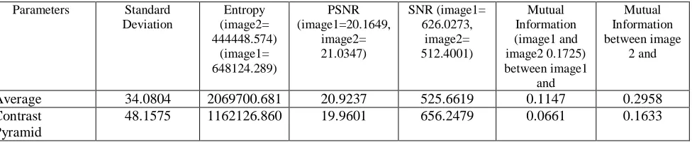
TABLE 1. Comparison Table for various metrics of fused images by different fusion methods
Parameters Standard Deviation Entropy (image2= 444448.574) (image1= 648124.289) PSNR (image1=20.1649, image2= 21.0347) SNR (image1= 626.0273, image2= 512.4001) Mutual Information (image1 and image2 0.1725) between image1 and Mutual Information between image 2 and
Average 34.0804 2069700.681 20.9237 525.6619 0.1147 0.2958 Contrast
Pyramid
(maximum) Contrast pyramid (Saliency)
47.2929 1146609.768 20.0799 638.3911 0.0670 0.1641
DWT using DBSS (Maximum)
37.1452 839303.601 20.8134 539.1833 0.1218 0.2702
DWT using DBSS (Saliency)
37.0829 839269.800 20.9596 521.3401 0.1220 0.2729
FSD Pyramid (Maximum)
43.2201 837938.882 20.9577 521.5643 0.1284 0.2857
FSD Pyramid (Saliency)
36.7677 840820.493 20.6955 554.0292 0.1215 0.2772
Gradient Pyramid (Maximum)
39.5550 832587.729 20.6679 557.5622 0.1266 0.2726
Gradient Pyramid (Saliency)
43.5495 846456.187 20.7819 543.1076 0.1245 0.2773
Laplacian Pyramid (Maximum)
62.1221 899659.270 20.7366 548.8037 0.1577 0.3738
Laplacian Pyramid (Saliency)
53.5563 818760.516 20.8820 530.7338 0.1395 0.2990
Morphological Pyramid (Maximum)
55.9516 804734.901 20.8583 533.6404 0.1519 0.2958
Morphological Pyramid (Saliency)
55.7033 811536.554 20.9759 519.3899 0.1459 0.2954
PCA 51.8598 794921.564 21.1138 503.1590 0.1771 0.4293 Ratio Pyramid
(Maximum)
64.2068 796933.194 20.8718 531.9905 0.1655 0.3660
Ratio Pyramid (Saliency)
43.5821 856597.571 20.6487 560.0331 0.1336 0.3064
Maximum 59.4959 784228.514 21.1938 493.9709 0.1842 0.4367 Minimum 17.2288 1173396.461 20.0271 646.2020 0.0448 0.0919 SIDWT using
HAAR (Maximum)
46.3233 842871.565 20.6006 566.2631 0.1325 0.2683
SIDWT using HAAR (Saliency)
47.6470 851213.480 20.6088 565.2031 0.1249 0.2669
V. CONCLUSION
In severe situations like accidents occur, majority of registered cases are for bone or head injury. For proper diagnosis, both CT scan and MRI scan are required to study the damage occurred for skull as well as for the internal organ injury of brain for the development of any brain tumors. If a combination of both images is present in a single image, then diagnosing the patient would be easier. Hence a generic mutliresolution fusion scheme is used to evaluate the fused image by various linear and nonlinear techniques. Among them contrast or morphological pyramid prove to be better methods if good SNR and PSNR are required respectively. Also Ratio or Laplacian Pyramid for standard deviation, Average method for Entropy and by Principal Component Analysis or Select Maximum Method for Mutual Information proved to be better choices. Hence based on the requirement i.e., the choice of features like similarity, contrast, rich information and better quality of fused images, the choice of fusion method can be done to assess medical images for proper immediate diagnosis.
6. ACKNOWLEDGEMENTS
This paper is dedicated to our Parents, Colleagues and Friends for their support without which the successful completion of this paper is not possible.
REFERENCES
1. Deepali A.Godse, Dattatraya S. Bormane “Wavelet based image fusion using pixel based maximum selection rule” International Journal of Engineering Science and Technology (IJEST), Vol. 3 No. 7 July 2011, ISSN : 0975-5462.
2. Chetan K. Solanki Narendra M. Patel, “Pixel based and Wavelet based Image fusion Methods with their Comparative Study”. National Conference on Recent Trends in Engineering & Technology. 13-14 May 2011.
3. Anjali Malviya, S. G. Bhirud .” Image Fusion of Digital Images” International Journal of Recent Trends in Engineering, Vol 2, No. 3, November 2009.
4. V.P.S. Naidu and J.R. Raol, “Pixel-level Image Fusion using Wavelets and Principal Component Analysis”. Defence Science Journal, Vol. 58, No. 3, May 2008, pp. 338-352 Ó 2008, DESIDOC.
5. Gonzalo Pajares , Jesus Manuel de la Cruz “A wavelet-based image fusion tutorial” 2004 Pattern Recognition Society.
6. Susmitha Vekkot, and Pancham Shukla “A Novel Architecture for Wavelet based Image Fusion”. World Academy of Science, Engineering and Technology 57 2009.
7. Rishu Garg, Preeti Gupta and Harvinder Kaur “Survey on Multi-focus Image fusion algorithms”. In Proceedings of RAECS UIET Panjab University Chandigarh, IEEE, 2014.
8. L Ganesh, S P Krishna Chaitanya, J Durga Rao and M N V S S Kumar. “Development of Image Fusion Algorithm for Impulse Noise Removal in Digital Images using the quality Assessment in Spatial Domain” In International Journal of Engineering Research and Applications (IJERA) Vol. 1, Issue 3, 2007.
9. Lixin Liu, Hongyu Bian and Guofeng Shao. “An Effective Wavelet-based Scheme for Multi-focus Image Fusion” In IEEE International Conference on Mechatronics and Automation (ICMA), 2013.
10. Qingping Li, Junping Du, Fuzhao Song, Chao Wang, Honggang Liu, Cheng Lu. “Region-based Multifocus Image Fusion Using the Local Spatial Frequency”, In Control and Decision Conference (CCDC), 25th Chinese, IEEE, 2013.
FIGURES
Figure 1: Generic Multiresolution Fusion Scheme
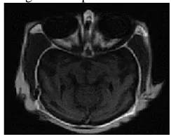
Figure 3: Medical Image2
Figure 4: Fused image by AverageFusion Method
Figure 5: Fused Image by PCA Method
Figure 6:Fused Image by Select Maximum Method
Figure 8: Fused Image by laplacian Pyramid with choose maximum as Highpass combination and average as low pass combination
Figure 9: Fused Image by laplacian Pyramid with saliency/MatchMeasure as Highpass combination and average as low pass combination
Figure 10: Fused Image by FSD Pyramid with maximum as Highpass combination and average as low pass combination
Figure 12: Fused Image by Ratio Pyramid with Maximum as Highpass combination and average as low pass combination
Figure 13: Fused Image by Ratio Pyramid with saliency/MatchMeasure as Highpass combination and average as low pass combination
Figure 14: Fused Image by Contrast Pyramid with Maximum as Highpass combination and average as low pass combination
Figure 15: Fused Image by Contrast Pyramid with Saliency/MatchMeasureas Highpass combination and average as low pass combination
Figure 16: Fused Image by Gradient Pyramid with Maximum as Highpass combination and average as low pass combination
Figure 18: Fused Image by DWT with DBSS(2,2) with Maximum as Highpass combination and average as low pass combination
Figure 19: Fused Image by DWT with DBSS(2,2) with Saliency/Match Measure as Highpass combination and average as low pass combination
Figure 20: Fused Image by SIDWT with Haar with Maximum as Highpass combination and average as low pass combination
Figure 21: Fused Image by SIDWT with Haar with Saliency/Match Measure as Highpass combination and average as low pass combination