WATERMARKING METHOD BASED ON DCT
INTENDED FOR HIGH EMBEDDING CAPACITY
Sahil G. Mujawar1 and Amar A. Dum2
I.INTRODUCTION
These days the copyright destruction has become a serious issue. Consequently, the demands for the copyright protection of digital multimedia are growing. The digital watermarking is a promising technique way out. In digital watermarking, the copyrighted information (such as signature, logo, ID number, etc.) is embedded into multimedia file itself. When owners want to proclaim their copyright, they can extract this copyright information.
With regards to image watermarking, imperceptibility, robustness, embedding capacity and security are of essential concerns. Until now, various image watermarking techniques were built, such as histogram, moment, spatial feature region, spread spectrum (SS) and quantization. As go through available literature, it is clear that, all watermarking methods developed are promises to tackle the piracy problem and with some extent of these major points. Different methods have different extent of these points. In numerous applications, for example, covert communication, high embedding capacity is required.
Compared to the Histogram, moment and spatial feature region watermarking methods, the methods based on SS and quantization can normally achieve higher embedding capacity under given imperceptibility and robustness. But, the SS-based watermarking approach suffers from the problem of host signal interference (HSI). It is known that HSI can greatly degrade the performance of watermark detection, especially in the presence of attacks, and thus lower robustness. However, similar to the SS-based watermarking methods, the quantization based watermarking methods do not perform well under high embedding rates. The remainder of the paper is organized as follows. Section II introduces the proposed image watermarking method. The simulation results are shown in Section III. Section IV concludes the paper.
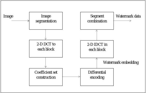
II.PROPOSED METHOD 2.1 Embedding part-
Consider a grey level host image I of size R × C. Without loss of generality, I is partitioned into N non-overlapping blocks I1, I2,…, IN, where the size of each block is M × M and M is a positive integer power of ‘2’. The 2-D discrete cosine transform is applied to each block to obtain the DCT counterparts F{I1}, F{I2},…, F{IN} of dimension M × M. Since low frequency components carry perceptually important information and high frequency
1
Department of Electronics Technology Dept. of Technology, Shivaji University, Kolhapur, Maharashtra, India
2
Department of Electronics Technology Dept. of Technology, Shivaji University, Kolhapur, Maharashtra, India
DOI: http://dx.doi.org/10.21172/1.83.041 e-ISSN:2278-621X
Abstract- In digital image watermarking, for applications like covert communication, high embedding capacity is desired. Hence, new method is proposed, which consists of two parts – embedding part and detection part. In first part, first step is dividing image into small blocks. Then DCT is applied to each block and embed the watermark data into image block. Here, the secret key is used to randomly select the DCT coefficients from middle frequency area of image. A secret key is used for security purpose. In detection part, the detection matrices are formed from received image to extract the watermark data. The proposed method requires only 3 coefficients to hide 2 watermark bit, normally it can achieve high embedding capacity.
components are vulnerable to image compression attack, it is appropriate and common to use the DCT coefficients corresponding to the middle frequency range for watermark embedding. In each block, we use a secret key to randomly select ‘s’ suitable DCT coefficients to form a DCT coefficient set, where the ‘s’ is the number which is multiple of 3.The purpose of using a secret key is to introduce security.
Image Watermark data
Watermark embedding
Figure 1. Block diagram of Watermark embedding part
Denote the length-s coefficient set in the n’th block by
Xn = [Xn(1), Xn(2), . . . , Xn(s)] (1)
where n = 1,2,. . . ,N. From Xn we can obtain ‘K’- groups containing 3 DCT coefficients each. The DCT coefficients
set of k’th group is
Xn,k = [Xn(k - 2), Xn(k - 1), Xn(k)] (2)
where k = 1, 2, . . . . , K. Based on (1) and (2), it follows
Xn = [Xn,1, Xn,2, . . . , Xn,K ] (3)
where n = 1,2,. . . ,N. Each group of DCT coefficients will be used to hide two watermark bits.
wn = [wn(1), wn(2), . . . , wn(Z)] (4)
be the sequence of ‘Z’ watermark bits to be embedded into the n’th image block, where the watermark bits wn(z), z
= 1,2, . . . ,Z. take values from {0,1}. Hence, the total length of the watermark sequence is N×Z. Then, check whether, if Xn(k - 2) = Xn(k - 1), then adding some constant ‘c’ to Xn(k-2).
i.e. Xn(k - 2) = Xn(k – 2) + c
Similarly, if Xn(k - 1) = Xn(k), then adding some constant ‘c’ to Xn(k).
i.e. Xn(k) = Xn(k) + c
where, ‘c’ can be any non-zero value.
Now, define the 3×3matrix An, and initiate it as a zero matrix.
Let,
A1 , A2 ,
A3 , A4 , (5)
For k’th group of coefficients, update the values of An based on values of watermark data, as shown in Table 1.
Image segmentation
2-D DCT to each block
Coefficient set construction
Segment combination
2-D IDCT in each block
Then multiply k’th group of coefficients with matrix An, to form Yn.
Yn = Xn,k An. (6)
where, n = 1, 2, . . . , N.
Table - 1 Matrix An up-gradation
Wn(z-1) Wn(z) An
0 0 A1
0 1 A2
1 0 A3
1 1 A4
Let,
Yn = [ Yn(1), Yn(2) . . . , Yn(S)]. (7)
be the watermarked counterpart of Xn.
The sequence of watermark bits Wn is embedded into Xn using the formula (6). By replacing Xn in F{ In} with Yn,
one can get the watermarked counterpart of F{In}, denoted a F{ InW }. After that, we apply the 2-D inverse discrete
cosine transform (IDCT) to F{ InW } to obtain the watermarked image block InW. Finally, the watermarked image IW
can be constructed by combining all of the watermarked image blocks together.
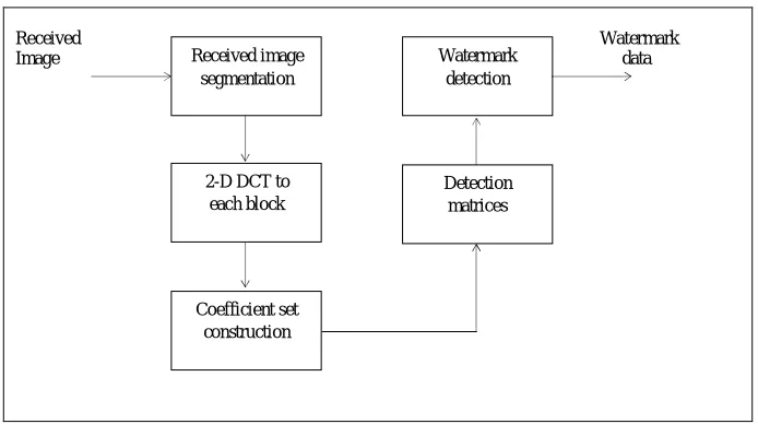
2.2 Detection part-
Received Watermark Image data
Figure 2. Block diagram of Watermark detection part.
Denote the received image as I’. Similar to the embedding process, I’ is divided into N non-overlapping blocks. I1’,I2’, . . . , IN’ of dimensions M×M. Applying 2-D DCT to the received image blocks yields the corresponding DCT components F{I’1}, F{I’2},…,F{I’N} of dimensions M×M. In the n’th block F{I’n}, the secret key can be used to find the length- ‘s’ DCT coefficients set Xn containing Z watermark bits. Denoting by
X’n = [X’n(1), Xn(2) . . . , X’n(S)] (8)
where n = 1,2,. . . ,N. From X’n we can obtain K- groups of 3 DCT coefficients each. The DCT coefficients set of
k’th group is
X’n,k = [X’n(k - 2), X’n(k - 1), X’n(k)] (9)
where k = 1, 2, . . . . , K. Based on (8) and (9), it follows
X’n = [X’n,1 , X’n,2 , . . . , X’n,K ] (10)
where n = 1,2,. . . ,N.
Received image segmentation
2-D DCT to each block
Coefficient set construction
Watermark detection
One can sequentially compute,
1n(k) = | X’n(k - 2) - X’n(k - 1)| and 2n(k) = | X’n(k - 1) - X’n(k)|. (11)
And
T1’(k) = max { 1n(k), 0} and T2’(k) = max { 2n(k), 0} . (12)
Based on T1’(k) and T2’(k), construct the detection matrices X1n,k and X2n,k for the extraction of the wn(z-1) and
wn(z) watermark bit resp. in k’th group of n’th block.
X1n,k and X2n,k (13)
Where, k = 1, 2, . . . , K and n = 1, 2, . . . , N.
In order to use X1n,k and X2n,k to extract the watermark bits (i.e.: wn(z-1) and wn(z)), let us analyse the property of
X1n,k in the absence of attacks. Since attacks are absent, it is obvious that I’ = Iw, which results in X’n = Yn or
X’n(s) = Yn(s). The analysis is conducted for two cases as following.
Case 1) Consider, watermark bits are wn(z-1) = 0 and wn(z) = 0, for k’th group of coefficients in for n’th block. And,
Xn(k - 2) Xn(k - 1) Xn(k)
For this case, it follows from equations (5), (6) and table no.1. [Xn(k - 2), Xn(k - 1), Xn(k)]
= [Xn(k - 2), Xn(k - 1), Xn(k)]. A1
= (14)
which means,
| Xn(k - 2) - Xn(k - 1)| = 0 and | Xn(k - 1) - Xn(k)| = 0.
Since, X’n(s) = Yn(s), it yields from (11) and (14) that
1n(k) = 0, and 2n(k) = 0. (15)
Based on (12) and (15) it follows
T1’(k) = max {0,0} = 0 and T2’(k) = max {0,0} = 0 (16)
Substituting (16) into (13), we can see that both detection matrices are rank deficient as its entries have the same value ‘0’.
Case 2) Consider, watermark bits are wn(z-1) = 1 and wn(z) = 1, for k’th group of coefficients in for n’th block. And,
Xn(k - 2) Xn(k - 1) Xn(k)
For this case, it follows from equations (5), (6) and table no.1. [Xn(k - 2), Xn(k - 1), Xn(k)]
= [Xn(k - 2), Xn(k - 1), Xn(k)]. A4
= [Xn(k - 2), Xn(k - 1), Xn(k)] (17)
Since, X’n(s) = Yn(s), it yields from (11) and (17) that
1n(k) = Xn(k - 2) - Xn(k - 1) and 2n(k) = Xn(k - 1) - Xn(k). (18)
T1’(k) = max { 1n(k),0} = 1n(k) and T2’(k) = max { 2n(k),0} = 2n(k) (19)
Substitute (19) into (13)
X1n,k , and X2n,k (20)
We can see that, the ranks of detection matrices X1n,k and X2n,k resp., are full of rank.
Similarly, for wn(z-1) = 0 and wn(z) = 1. The rank of detection matrix X1n,k is rank deficient and while rank of X2n,k
is full of rank. Since, in that case, we can find, the values T1’(k) = ‘0’ and T2’(k) = 2n(k).
Similarly, for wn(z-1) = 1 and wn(z) = 0. The detection matrix X1n,k is full of rank and X2n,k is rank deficient. Since,
in that case, we can find, the values T1’(k) = 1n(k) and T2’(k) = ‘0’.
Based on the rank of X1n,k and X2n,k , the wn(z-1) and wn(z) watermark bit in the nth block can be extracted using
the following detection rule:
Table - 2 Detection matrices
Detection Matrices Watermark data
X1n,k X2n,k W’n(z-1) W’n(z)
Rank deficient Rank deficient 0 0
Rank deficient Full of rank 0 1
Full of rank Rank deficient 1 0
Full of rank Full of rank 1 1
Where k = 1, 2,…, K and n = 1, 2,…,N. Finally, the extracted watermark sequences w’n(1), w’n(2) ,…,w’n(Z)can be
obtained by combining all of the detected watermark bits.
III.SIMULATION RESULTS
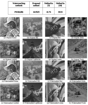
Evaluation of the performance of proposed system is carried out by simulations, in comparison with methods [5], [10]. Eight standard 512 512 8-bit gray scale images Elaine, Hill, Bee, Zelda, Goldhill, Lighthouse, Lenna, and Truck used as host(original) images as shown. The peak signal-to-noise ratio (PSNR) index and the bit error rate (BER) index are utilized to measure perceptual quality and robustness, respectively. The performance parameters PSNR and BER are figured by averaging the outcomes acquired from the eight images. With respect to, the bigger PSNR esteem the better perceptual quality. It is specified in [12] that the PSNR estimation of 40dB shows great perceptual quality.
For instance, the bottom two rows of Figure 4. shows, the watermarked counterparts of the up to said eight images by our technique, where PSNR = 44.9525dB. Obviously, there is no visual difference between the original images and their watermarked images. With respect to robustness, a littler BER value shows better robustness, and vice-versa. In the simulations, we choose N = 4096 for all images. Embedding rates is considered as 16384 watermark bits per image, which correspond to K = 2.
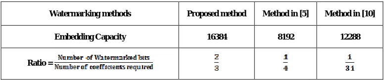
3.1 Embedding capacity-
Embedding rate is 16384 bits which is much more than other methods. Proposed method achieves high embedding capacity, since our method required as little as ‘3’ coefficients to embed ‘2’ watermark bits.
Table - 3 Watermarking Embedding capacity for different methods
Watermarking methods Proposed method Method in [5] Method in [10]
Embedding Capacity 16384 8192 12288
(a) Original Elaine (b) Original Hill (c) Original Bee (d) Original Zelda
(e) Original Goldhill (f) Original Lighthouse (g) Original Lenna (h) Original Truck
(a) Watermarked Elaine (b) Watermarked Hill (c) Watermarked Bee (d) Watermarked Zelda
(e) Watermarked Goldhill (f) Watermarked Lighthouse (g) Watermarked Lenna (h ) Watermarked Truck
3.2 Imperceptibility-
PSNRs of different watermarking methods are as shown in Table 4. Obviously, there is no any difference in original images and corresponding watermarked images. Hence, the proposed system is imperceptible.
Table - 4 PSNR value for different methods
Watermarking methods
Proposed method
Method in [5]
Method in [10]
PSNR(dB) 44.9525 41.76 39.93
Figure 4. Upper two rows - Original images Elaine, Hill, Bee, Zelda, Goldhill, Lighthouse, Lenna, and Truck. Lower two rows: watermarked counterparts of these images.
3.3 Robustness-
3.3.1 In the absence of attack-
For any watermarking method its BER value obtained in the absence of attacks indicates the impact of HSI. Since HSI does not exist in the proposed method, perfect watermark detection can be achieved.
Table - 5 BER in the absence of attack
Watermarking methods Proposed method Method in [5] Method in [10]
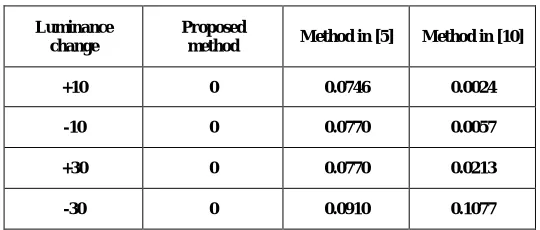
3.3.2 In the presence of constant luminance change attack -
Table – 6 BER in the presence of attack
Luminance change
Proposed
method Method in [5] Method in [10]
+10 0 0.0746 0.0024
-10 0 0.0770 0.0057
+30 0 0.0770 0.0213
-30 0 0.0910 0.1077
Table 6 shows that, BER of our method remains ideal in the presence of constant luminance change attacks. This is because the constant luminance change does not alter the DCT coefficients of the watermarked image block, except for the DCT coefficient at (u, v) = (0, 0) [11]. Since, the proposed system uses medium frequency region to select DCT coefficients for watermark embedding. Hence, there is no any change in BER in the presence of constant luminance change attack.
IVCONCLUSION
In this paper, we proposed a new technique for image watermarking in the DCT area. The proposed watermarking technique has some necessary striking features. Our technique can use as little as three DCT coefficients to embed two watermark bits, which leads to high embedding capacity. Secondly, the proposed system is free of HSI. Thirdly, it can remarkably tolerate the errors brought on by attack. Second and third features make the proposed technique robust against constant luminance change attack. The superior execution of the new strategy was verified by simulation results.
REFERENCES
[1] S. Xiang, H. J. Kim, and J. Huang, ''Invariant image watermarking based on statistical features in the low-frequency domain,'' IEEE Trans.
Circuits Syst. Video Technol., vol. 18, no. 6, pp. 777-790, Jun. 2008.
[2] T. Zong, Y. Xiang, I. Natgunanathan, S. Guo, W. Zhou, and G. Beliakov, ''Robust histogram shape-based method for image watermarking,''
IEEE Trans. Circuits Syst. Video Technol., vol. 25, no. 5, pp. 717-729, May 2015.
[3] M. Alghoniemy and A. H. Tew_k, ''Geometric invariance in image watermarking,'' IEEE Trans. Image Process., vol. 13, no. 2, pp. 145-153,
Feb. 2004.
[4] P. Dong, J. G. Brankov, N. P. Galatsanos, Y. Yang, and F. Davoine, ''Digital watermarking robust to geometric distortions, '' IEEE Trans.
Image Process., vol. 14, no. 12, pp. 2140-2150, Dec. 2005.
[5] M. Li, M. K. Kulhandjian, D. A. Pados, S. N. Batalama, and M. J. Medley, ''Extracting spread-spectrum hidden data from digital media,''
IEEE Trans. Inf. Forensics Security, vol. 8, no. 7, pp. 1201-1210, Jul. 2013.
[6] X. Gao, C. Deng, X. Li, and D. Tao, ''Geometric distortion insensitive image watermarking in affine covariant regions,'' IEEE Trans. Syst.,
Man, Cybern. C, Appl. Rev., vol. 40, no. 3, pp. 278-286, May 2010.
[7] I. J. Cox, J. Kilian, F. T. Leighton, and T. Shamoon, ''Secure spread spectrum watermarking for multimedia,''IEEE Trans. Image Process., vol.
6, no. 12, pp. 1673-1687, Dec. 1997.
[8] J. Cannons and P. Moulin, ''Design and statistical analysis of a hash-aided image watermarking system,'' IEEE Trans. Image Process., vol. 13,
no. 10, pp. 1393-1408, Oct. 2004.
[9] H. S. Malvar and D. A. F. Florencio, `''Improved spread spectrum: A new modulation technique for robust watermarking,'' IEEE Trans. Signal
Process., vol. 51, no. 4, pp. 898-905, Apr. 2003.
[10] Q. Li and I. J. Cox, ''Using perceptual models to improve fidelity and provide resistance to valumetric scaling for quantization index
[11] T. Zong, Y. Xiang, S. Guo and Y. Rong, "Rank-Based Image Watermarking Method With High Embedding Capacity and Robustness," in
IEEE Access, vol. 4, no., pp. 1689-1699, 2016.
[12] H. Zhang et al., ''Affine Legendre moment invariants for image watermarking robust to geometric distortions, '' IEEE Trans. Image Process.,
vol. 20, no. 8, pp. 2189-2199, Aug. 2011.
[13] P. C. Su, Y. C. Chang, and C. Y. Wu, ''Geometrically resilient digital image watermarking by using interest point extraction and extended
pilot signals,'' IEEE Trans. Inf. Forensics Security, vol. 8, no. 12, pp. 1897-1908, Dec. 2013.
[14] A. K. Parthasarathy and S. Kak, ''An improved method of content based image watermarking,'' IEEE Trans. Broadcast., vol. 53, no. 2, pp.