118006-3535 IJMME-IJENS © December 2011 IJENS
I J E N S
Analysis of Cutting Process of Materials Using Low Power Laser Diode and
CO
2Ario Sunar Baskoro, Herwandi, KGS Ismail, Agus Siswanta, Gandjar Kiswanto Mechanical Engineering Department, Faculty of Engineering, Universitas Indonesia, Depok, Indonesia
Abstract: Recently the use of laser to various kinds of applications has been applied. Therefore, to obtain better results in the development of a cutting machine of materials using low power laser, cutting system should be analyzed, both in simulation and experiment. In this experiment, low power laser diode and laser CO2 were used. The gypsum and polymer materials were
used in this experiment. For the simulation of cutting process, software was used while the experimental process used CNC milling machine as a manipulator. From the research it is shown that parameters such as speed, current, voltage, number of pass, number of layer and compressed air influence the depth of cut in the process of cutting. By using Response Surface Method (RSM), in laser CO2 cutting for gypsum it is found that power and number of layer have significant effect to make
depth of cut deeper, while the speed has no significant effect to increase the depth of cut. Keywords: laser cutting, low power laser diode, laser CO2, response surface method.
1 INTRODUCTION
Recently, the application of laser (light amplification by stimulated emission of radiation) has been widely used in many fields such as manufacturing, biomedical, etc. The important element that make laser more practical is the light amplification achieved by stimulated emission due to the incident photons of high energy. Laser process is one of the advanced machining processes such as electrical discharge machining (EDM), laser beam machining (LBM), ion beam machining, electron beam machining, plasma beam machining, chemical machining, electro-chemical machining, water jet machining and abrasive water jet machining. This process can handle the intricate shape and unusual size of the work material [1]. The example of this application is in cutting process using engraving laser machine by removing small part of the surface of materials with different depth. Laser cutting produces a finer finish to the end product as compared to conventional cutting methods. Laser is widely used to cut precise shapes into plastic or acrylic sheets with varying thickness. Because the laser process is non-contact process, the wear and tear associated with conventional method is absent, preventing the product from any damage and deformation [2]. One of the laser machines is laser diode. The high-power diode laser has advantages such as compactness, energy efficiency, lifetime and running costs [3]. The prediction model of melt depth in architectural materials during high power diode laser treatment has been investigated [4]. And three-dimensional model for direct laser metal powder deposition and rapid prototyping has been studied [5].
The application of cutting process for polymer materials has been developed. The research on cutting process to produce good product should be conducted. In this experiment, the low power laser diode and laser C02 were used. The results of experiment in
cutting process were analyzed to understand the influence of parameters such as: cutting speed, number of pass, number of layer, voltage and current (power) of laser to the depth of cut.
2 EXPERIMENTAL SETUP
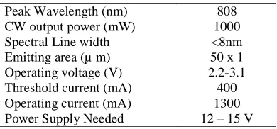
Experimental apparatus is shown in Figure 1.a and 1.b. The system consists of CNC Milling machine TU-3A, laser diode, laser diode holder and nozzle for compressed air. The specification of laser diode 1000 mW used in this experiment is shown in Table 1. After measuring the power of laser, the real power of laser was 737 mW from the designed specification of 1 mW. The voltage and current controller was constructed to control the power of the laser.
Table 1. Laser diode specification
Peak Wavelength (nm) 808
CW output power (mW) 1000
Spectral Line width <8nm
Emitting area (µ m) 50 x 1
Operating voltage (V) 2.2-3.1
Threshold current (mA) 400
Green acrylic (nm) 492-577
Table 3. Process parameter
Parameter Laser diode Laser CO2 Material Black and green acrylic Gypsum
Material form Plate Plate
Speed 10, 20, 30, 40, 50 (in mm/min)
6, 7, 8, 9, 10 (in mm/s)
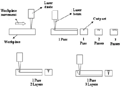
Pass 1, 3, 5 1
Layer 1, 2, 3 1, 2, 3, 4, 5
Power 1.1 A – 13.9 V, 1.04 A – 11.8 V, 0.87 A – 10.3
V, 0.79 A – 9.7 V
12, 24, 36, 48, 60 (in Watt)
The temperature of laser beam was measured using thermocouple. It shows for the range of voltage 10.3 V – 13.6 V and current 0.87 A – 1.1 A produced temperature 148 oC – 218 oC. This temperature is suitable for cutting process of polymer materials.
CNC milling machine as a manipulator used in this experiment has the capability to move in 3-axis automatically. The laser diode was mounted on the head of spindle using the laser holder. Nozzle was used to deliver compressed air on the surface.
The maximum power of laser CO2 used for cutting
materials is 60W. The power of the laser is varied from 12W to 60W.
Material properties used in this experiment is shown in Table 2. There are 2 types of acrylic material with different color of black and green. These different materials were investigated to study the capability of cutting process of laser diode. The other material is gypsum that made it by mixing with the some water.
Figure 2 shows the cutting process. Process parameters used in this experiment is shown in Table 3. The material was place in the container on the table with the movement of X-axis and Y-axis and beamed by the laser.
a. Schematic of experiment apparatus
b. Laser diode experimental apparatus
c. Laser CO2 experimental apparatus
Figure 1. Experimental apparatus
118006-3535 IJMME-IJENS © December 2011 IJENS
I J E N S
Before the process, the movement of table was set and programmed in CNC machine. Then the height of laser diode was set respect to the surface of workpiece. After setting the current and voltage of laser, the process was started. The final product was measured with the digital microscope and captured with camera to take the depth of cutting.
3 DEPTH OF MOLTEN POOL
The theoretical model for calculating the depth of cut during cutting process used the previous approach [4-5]. The model applies by calculating depth of molten pool using the following considerations:
- The initial workpiece temperature T0 may be
neglected compared to the melting temperature Tm
- The latent heat of fusion is small compared to the total energy required for processing
- Assuming the meltpool diameter equal to the laser beam diameter.
The equation is shown in Eq. 1.
v d k T C Cp
P A y
m L m
. . .
. . . 2
2
ρ
= (1)
Where:
ym = depth of molten pool (m)
A = laser absorptivity of workpiece
PL = laser power (W)
ρ = density (kg/m3)
Cp = spesific heat (J/kg.⁰K)
C2 = correction factor = 4.31
Tm = melting temperature (⁰K)
k = thermal conductivity (W/m.⁰K)
d = diameter of laser beam (m)
v = traverse speed (m/s)
4 RESULTS AND DISCUSSION
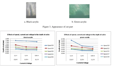
Figure 3 – 6 show the results of cutting process. Figure 3 shows the appearance of the acrylic surface after cutting process. Effects of speed, current and voltage to the depth of cut are shown in Figure 4.a and 4.b.
a. Black acrylic b. Green acrylic Figure 3. Appearance of cut part
a. Black acrylic b. Green acrylic
a. Black acrylic b. Green acrylic Figure 5. Effects of number of pass and speed to the depth of cut
a. Black acrylic b. Green acrylic
Figure 6. Effects of number of pass and layer to the depth of cut
(a) 1 layer (b) 2 layers
(c) 3 layers (d) 4 layers
118006-3535 IJMME-IJENS © December 2011 IJENS
I J E N S
It shows that the higher speed, the lower depth of cut. With the decreasing of current and voltage, the lower depth of cut occurs. Figure 5.a and 5.b shows the effects of pass and speed to the depth of cut. It shows that the more pass, the higher depth of cut. Figure 6.a and 6.b show the effects of number of pass and layer to the depth of cut.
It shows that the higher number of pass and layer, the higher depth of cut. However, the increase of depth of cut is not linear. This is because the cutting process creates sintered surface that can resist the laser beam to penetrate to the surface. From the result, it shows that speed, current, voltage, number of pass and number of layer influence the depth of cut.
Figure 7 shows results of depth of cut using laser CO2.
It is shown that for constant number of layer, the higher power, the deeper depth of cut. And the higher number of layer, it is not significantly make the depth of cut deeper. Figure 8 shows the appearance of cut surface of gypsum using laser CO2.
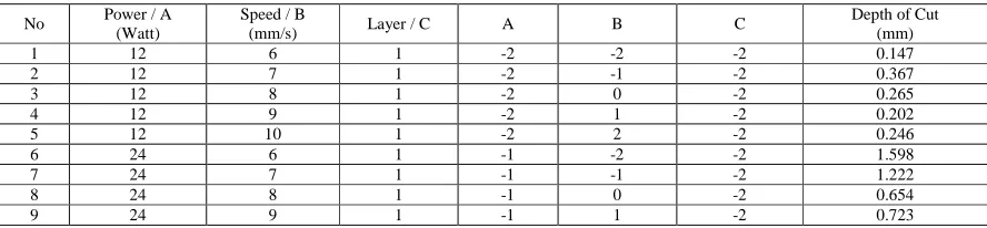
To analyze the correlation of the parameters during cutting process, the Response Surface Method (RSM) is used for selecting which the parameter that has less significant effect to the depth of cut. Table 4 shows the sample of the data used for RSM analysis. The total number of data is 125 pairs of data. The parameter A is laser power, B is speed and C is number of layer. After calculating the RSM, it is determined that the regression equation is:
Y = 3.007 + 0.7854 A - 0.1382 B + 0.9272 C (2)
Since the B (speed) parameter has negative value, then this parameter has no effect significantly to the depth of cut, while the parameter A (power) and C (number of layer) have significant effect to the raise the depth of cut.
Compared with previous experiments, this experiment has investigated the cutting process using low power laser diode and laser CO2. The analysis of the
experiment shows that significant parameters during cutting process are the power of laser and number of layer.
For further development, the research will be focused on prototyping of biomedical devices such as artificial implant, artificial bone, etc. The cutting process will consider the parameters of power and number of layer to make good prototypes.
5 CONCLUSIONS
- The cutting process for polymer materials which are black and green acrylic materials has been conducted using low power laser diode and gypsum using laser CO2.
- The depth of cut during cutting process is influenced by speed, current, voltage number of pass, number of layer and compressed air.
- From the RSM analysis, in laser CO2 cutting for
gypsum it is found that power and number of layer have significant effect to make depth of cut deeper, while the speed has no significant effect to increase the depth of cut.
a. Power = 12W, speed=6mm/s, layer=1,depth=0.147mm b. Power = 24W, speed=6mm/s, layer=1,depth=1.598mm Figure 8. Cut surface of gypsum using laser CO2
Table 4. Sample of table for Response Surface Method
No Power / A (Watt)
Speed / B
(mm/s) Layer / C A B C
Depth of Cut (mm)
1 12 6 1 -2 -2 -2 0.147
2 12 7 1 -2 -1 -2 0.367
3 12 8 1 -2 0 -2 0.265
4 12 9 1 -2 1 -2 0.202
5 12 10 1 -2 2 -2 0.246
6 24 6 1 -1 -2 -2 1.598
7 24 7 1 -1 -1 -2 1.222
8 24 8 1 -1 0 -2 0.654
6 REFERENCES
[1] Dubey, A.K. and Yadava, V. (2008), “Laser beam machining: a review”, International Journal of Machine Tool and Manufacture, 48, 609-628.
[2] Choudhury, I.A. and Shirley, S. (2010), “Laser cutting of polymeric materials: An experimental investigation”, Optics & Laser Technology, 42, 503-508.
[3] Li, L. (2000), “The advances and characteristics of high-power diode laser materials processing”, Optics and Laser in Engineering, 34, 231-253
[4] Lawrence, J., Peligrad, A.A., Zhou, E., Li, L. and Morton, D. (2001), ”Prediction of Melt Depth in Selected Architectural Materials during High Power Diode Laser Treatment”, Optics and Lasers in Engineering, 35 (1), 51-62.