Superconducting Transformers
Vasantkumar Upadhye
Assistant Professor,Department of Electrical and Electronics Engineering
Angadi Institute of Technology and Management, Belagavi, Karnataka, India
Utkarsh C. Savardekar
Department of Electronics and Communication Engineering Angadi Institute of Technology and Management, Belagavi, Karnataka, India
Abstract- Having a efficient power system now-a-days is of utmost importance. The superconducting transformer meets the requirements of limited space, cost and security while giving a better efficiency. This will give a brief generalized idea upon the superconducting transformer and will host a comparison between the conventional transformers and HTS transformers. It briefly summarizes the principles of superconductivity and HTS transformers while also addressing the elementary configuration of the HTS transformer
Keywords – Superconductivity, HTS, Transformer
I.INTRODUCTION
Transformers represent one of the oldest and most mature elements in a power transmission and distribution network. Transformers are needed to effect voltage conversions. At each conversion point, energy is lost, primarily in the form of wasted heat from changing electrical and magnetic fields in the copper (coil), iron (core), tank, and supporting structure. Even when the transformer is "idling," so-called "no-load losses" (NLL) are generated in the core. No-load losses represent some 10-20% of total losses and are the result of two major factors, hysteresis losses in the iron core (30-50% of NLL) and eddy current losses in the core, coil, tank and supporting structure (50-70% of NLL). Research over the last 50 years has succeeded in reducing NLL by a factor of three while increasing core costs by a factor of two.
Existing transformer technology would appear to leave little room for improvement. However, electric energy consumption continues to increase at about 2% per year nationally with most growth occurring in urban areas small to medium power range (10-100 MVA).This suggests a growth in the Recent substitution in distribution transformers (ratings below about 100 kVA) of amorphous metals for silicon iron core material has reduced NLL further, but this material has not been used in the cores of power transformers (ratings greater than 500 kVA). When a transformer is under a loaded condition, Joule heating (I2R losses) of the copper coil adds considerably to the amount of lost energy. Of this load loss, 80% are I2R losses. The remaining 20% consists of stray and eddy current losses. To date, efforts to reduce load losses have been directed toward the latter. Unlike copper and aluminium, superconductors present no resistance to the flow of dc electricity, with the consequence that I2R losses become essentially zero, thereby creating the potential for a dramatic reduction in overall losses.
The use of superconducting windings offers a means of reducing the major component of transformer losses (12R) and the volume and weight of power transformers. Even with the added cost of refrigeration, HTS transformers in the 10 MVA and higher range are projected to be substantially more efficient and less expensive than their conventional counterparts.
Motivation for developing superconducting transformers is not based solely on economic considerations of lowering total owning costs but also, With limited new siting availability in urban areas, means that existing sites must be uprated with higher power capabilities. Many existing sites are indoors or adjacent to buildings, which restricts the use of most oil-filled transformers. The inherent dangers of oil-filled devices are totally eliminated by application of superconducting technology where the only coolant required is benign (nitrogen as opposed to oil). Consequently, superconducting transformers operating either with a refrigerated coil or one cooled with liquid nitrogen pose no fire hazards and no threat to the environment comparable to that posed by leaks of flammable oils and toxic chemicals such as PCBs.
II.SUPERCONDUCTIVE TRANSFORMERS
2.1. LTS Transormers –
Serious interest in superconducting transformers began in the early 1960s as reliable low temperature superconductors based on Nb-Ti and Nb3Sn became available. Analysis of the feasibility of such LTS transformers concluded that the high refrigeration loads required to keep the LTS materials at 4.2 K made the LTS transformers uneconomical. Lorch in 1969 and Harrowell in 1970 again established the potential benefits and more clearly defined the problems to be solved, the superconducting transformer was still considered to be uneconomic, again primarily because of large total volume and high refrigeration loads. Lurch concluded that for the superconducting transformer to become economical the cost of refrigeration had to be drastically reduced either by a major development in refrigeration technology or by the development of superconductors with significantly higher operating temperatures.
Since 1980, development of LTS transformers has been conducted primarily by ABB and GEC-Alsthom in Europe and by various utilities, industries, and universities in Japan. Advances in production of long-length ultrafine multifilamentary Nb-Ti conductor and high resistivity Cu-Ni matrix materials have assisted in the reduction of ac losses. Feasibility of weight reduction and higher efficiencies has been demonstrated on smaller devices with ratings smaller than 100 kVA: single-phase 80 kVA (Alsthom), 30 kVA (Toshiba), and a three-phase 40 kVA (Osaka University).
2.2. HTS Transformers –
Immediately following the discovery of HTS (High temperature superconductivity) materials in 1986, several studies looked into the feasibility of HTS transformers. Savings over conventional units were estimated to be greater than 35%, but the unknown ac loss characteristics of the HTS materials made it difficult to assess viable designs. A comprehensive study conducted for the U.S. Department of Energy found the life-cycle costs of an HTS transformer, on average, to be half those of a comparable conventional unit. As expected, the HTS transformer was smaller and lighter; however, because of the unknown characteristics of the HTS cable and detailed cryogenic designs, size and performance projection are valid only for scoping purposes. Of the two major design approaches considered, the cryostable design, was more cost effective than the ultra-stable design because less was required. Mumford of GEC Alstrom describes the technical and economic benefits of HTS power transformers operating at 77 K. His lifecycle cost analysis indicates HTS transformer costs should be 30-60% of conventional transformer costs over the size range of 30-1500 MVA. Transformer weight was calculated to be about 60% of conventional; however, this reduction was due only to the change in conductor, and greater reduction may be possible.
Greater effective capacity: One major advantage of the HTS transformer is reduced size and weight. Another is a distinct environmental plus-in the conventional transformer; oil is a fire hazard and potential contaminant, whereas in the HTS transformer, the only substance present in large volume is non-flammable and environmentally benign liquid nitrogen. But perhaps the key advantage is the capability for over capacity operation, due in part to the low temperatures at which HTS windings operate.
Heat is the principle enemy of the paper-oil electrical insulation system of conventional power transformers.in order to meet the desired life of thirty or more years, transformer capacity ratings are based on holding the temperature of the hottest part of the insulation to under 110°C (or 95°C with transformers of older designs). Thermal damage is cumulative, so that operation at only 20°C over the limit for a total of 100 days-less than 1% of 30 years-will reduce a transformer's life by 25 percent. In view of this sensitivity, the thermal management of conventional transformers has received much attention in recent years. This is also because utility customers are making ever heavier use of air-conditioning systems, even in northern climates, giving rise to peak loading conditions that can last 10 hours or more on the hottest days of the year. Loss of insulation life can be significant under these conditions. So transformers are increasingly being purchased with excess capacity, just to meet maximum temperature limits that may occur only on a few days.
In contrast, HTS transformers, their windings, and insulations necessarily operate in the ultra-cold range of 20 K to 77 K (-253 °C to -196 °C), where insulations will not degrade. HTS units can run at rated power continuously and efficiently. In fact, at up to twice rated power, they can run for indefinite periods of time without any loss of operating life, albeit at greatly reduced efficiency because of a disproportionately increased use of liquid nitrogen or an increased refrigeration load. Thus one HTS transformer can in emergencies carry the loads normally handled by two, and HTS transformer lifetime can be greatly extended.
through a fault current of 10-12 times rated current. But they also can be configured to provide additional power system advantages. Preliminary analyses indicate that they can be built to have very low internal impedances and still, through an alternative fault-current-limiting transformer winding design, be self-protecting against the higher fault currents that could result, if needed, to limit the low-voltage side current to the rating of existing breakers. Low impedance makes the transformer better at maintaining output voltage levels over a wide range of operating power levels and better able to transmit power down-stream through the power system. Utilization of this feature will involve consideration of transformer interfaces with the grid and the load in each situation, and may especially apply to new power construction where a complete system of compatible components can be installed in an economical way.
Design trade-offs, cost drivers: Zero resistance and 10-100 times greater current density promise striking advantages in transformer size and performance. Classical resistive losses are eliminated, and the quantity of conductor in the HTS transformer windings can be reduced to tens as against thousands of kilograms for the conventional transformer. Since the windings in principle require little space and generate little resistive heat, it should be possible to make superconducting transformers inexpensively, with greatly reduced power capacity, much increased efficiency, and very much smaller size.
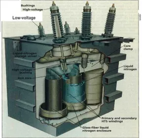
Figure 1. This artist’s conception of a superconducting transformer resembles conceptually the one being developed by intermagnetics general
and and Waukesha Electric. Note in particular the location of the liquid-nitrogen storage vessel, inside the top of the transformer box, and the enclosure containing liquid nitrogen around the primary and secondary superconducting windings.
III.ELEMENTARY CONFIGURATION OF HTSTRANSFORMER
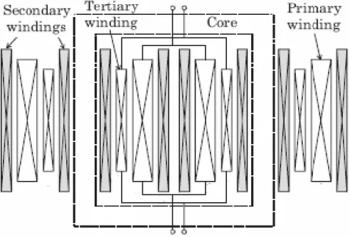
Figure 2. Principle structure of a HTS transformer
3.1. Windings –
HTS wires which are commonly used in high voltage power transformer can be divided into two types: the 1st generation Bismuth Strontium Copper Oxides (BSCCO) HTS wires, and the 2nd generation Yttrium-Barium- Copper Oxide (YBCO) HTS wires. For BSCCO, it is mainly applied in two forms: Bi2Sr2CaCu2O (Bi2212) and Bi2Sr2Ca2Cu3O (Bi2223). At present, Bi2223 has been more applied than Bi2212 since its critical temperature is 20 K higher than Bi2212.
To deal with high voltage, the superconducting power transformer needs windings which have hundreds of turns. A common windings configuration in HTS transformer is shown in Fig.5. BSCCO wires have been used to make the HTS windings. HTS winding with YBCO wires begin to be considered because YBCO wires have higher current density and better current magnetic field characteristics than BSCCO wires.
Figure 3. A winding and core configuration for a HTS transformer
3.2. Core –
3.3. Cryostat –
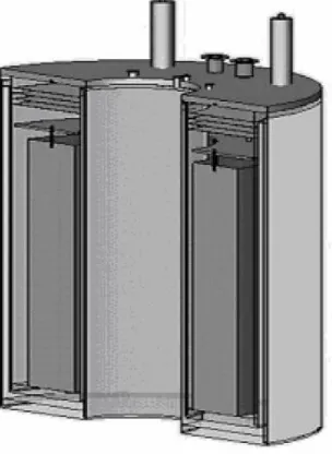
Cryostat is commonly manufactured by fiber reinforced plastic (FRP) in shape of toroid that core can go thorough in midway and have vacuum and super-insulation layer to minimize thermal invasion. Also, it acts as insulator between core and winding. Its configuration is shown in Fig.6.
Figure 4. Cryostat configuration
3.4. Refrigerator –
HTS wires, in which the critical temperatures are above 77 K, enable the cooling system to be simplified. This aspect makes it very advantageous when compared with the LTS system. However, the critical current of HTS materials decreases steeply as the magnetic field, especially the perpendicular component of the field, is applied. To overcome this weakness, the HTS materials can be cooled down below 77 K to increase the critical current. However, the operation in low temperature makes the cooling system more complicated. Recently the subcooled system is used worldwide and simply shown in Fig. 7. It cools down the temperature to about 65 K so that the HTS critical current at the zero applied field may be up to about 1.5 times of the critical current in 77 K. In addition, the subcooled nitrogen is superior over the liquid nitrogen in electrical insulating properties so that it may be easier to design the high voltage HTS power machines.
IV.ADVANTAGE
Lightweight, reduced size, high efficiency, fire safety. 100% overload capacity and eco-friendly with low CO2 emission.
Withstands overload without loss of insulation life and possesses inherent self-healing capacity during the faults - supports SMART grid.
Potential for fault current limiting capability, allowing reduced cost for associated switchgear, breakers, etc More than 100 times current carrying capacity compared to copper.
Negligible load losses
No fire hazards and no threat to the environment unlike flammable and toxic oils used in conventional transformers. Liquid Nitrogen abundantly used as a coolant and insulation, which is inert in nature; making HTS transformers safer and green device.
2X rating overload capability without insulation damage or loss of life
Table -1 Comparison Of Technical Features
Parameter HTS Conventional
Guaranteed % reactance
20 20
B in core, T 1.67 1.67
J rated, rms, A/mm2
38 2.83
Rated loss, total 23 100
Overload capability 2 pu, many hours 1.3 pu, 6 hours
1.5 pu, 30 mins Through fault
capability, pu (+ doubling transient), recovery
time without disconnection
2 pu,64 ms 5 pu, 3sec
Survival time at 5 pu (+ doubling
transient)
166ms Seconds(>3)
Table 1 show the comparision of the technical features between the conventional and HTS transformer
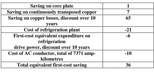
Table -2 Cost Savings On Continuous Full Load
Saving on core plate 1
Saving on continuously transposed copper 7
Saving on copper losses, discount over 10 years
65
Cost of refrigeration plant -21
First-cost equivalent expenditure on refrigeration
drive power, discount over 10 years
-6
Cost of AC conductor, total of 7371 amp-kilometres
-10
Total equivalent first-cost saving 36
IV.CONCLUSION
The characteristics and some application examples of superconducting transformers have been mentioned and described. Comparison of HTS transformers with conventional transformer has been made and it is concluded that HTS transformer provides greater efficiency, lower cost, lower area requirement and greater protection against faults in comparison.
REFERENCES
[1] Ronald C. Johnson, Benjamin W. McConnell, Sam P. Mehta, Michael S. Walker, “STATUS OF SUPERCONDUCTING POWER
[2] I. E. Chew, “SUPERCONDUCTING TRANSFORMER DESIGN AND CONSTRUCTION”, University of Canterbury, Christchurch, New Zealand. March 2010
[3] Professor Jan Sykulski,”SUPERCONDUCTING TRANSFORMERS”, Southampton, UK, ARWtr2004, 29 – 30 October 2004
[4] Beales, T.P., C.M. Friend, W. Segir, E. Ferrero, F. Vivaldi, L. Ottonello. 1996. “A DC TRANSMISSION CABLE PROTOTYPE USING
HIGH-TEMPERATURE SUPERCONDUCTORS”. Superconducting Science Technology 9:43-47 (UK)
[5] Mumford, F.J. 1994. “A TECHNO-ECONOMIC STUDY OF HIGH TC SUPERCONDUCTING POWER TRANSFORMERS”.
International Conference on Electrical Machines, Paris, France, Sept.
[6] Xiaoyuan Chen and Jianxun Jin, “DEVELOPMENT AND TECHNOLOGY OF HTS TRANSFORMERS”, University of Electronic
Science & Technology of China Barni M., Bartolini F., Piva A., Multichannel watermarking of color images, IEEE Transaction on Circuits and Systems of Video Technology 12(3) (2002) 142-156.
[7] S.W. Schwenterly, E.F. Pleva, C.S. Weber, “HTS POWER TRANSFORMERS”, 2003 DOE Peer Review Committee For the
WES/SP/RG&E/ORNL Team, Washington, D.C. July 24, 2003.