REDESIGN & FINITE ELEMENT ANALYSIS OF
INJECTION MOLDING MACHINE STATIONARY
PLATEN
1
Vicky K Thakor
1Assistant Professor
1Department of Mechanical Engineering
1Silver Oak College of Engineering and Technology, Ahmedabad, India
________________________________________________________________________________________________________
Abstract: Stationary platen is a critical component of plastic injection molding machine. During clamping of molds, force is
produced against the face of platen which will result in deformation of platen concavely. The platen also includes tie bars at each corner. As a result of bending of the platen, tie bars also resulting in uneven loading. The uneven loading results the premature failure of tie bar which can lead to the breakdown of the machine. The paper includes improvement in the design i.e. to eliminate the dome shape of 910 Ton stationary platen and make it flat, also increase injection unit entrance hole diameter and optimize the modified model. The work presented includes finite element analysis, fatigue analysis, design modifications and optimization of Injection Molding Machine Stationary Platen.
For 910T, finite element analysis is carried out and stress value is compared with acceptance criteria. For finite element based fatigue analysis of 910T, the life of platen checked for design life. For improvement in design modification is carried out. After design modifications, finite element analysis and fatigue analysis is carried out and checked with an acceptance limit of stress and design life.
Index Terms - Injection molding machine, finite element analysis, fatigue analysis, Stationary platen, and Design modifications
________________________________________________________________________________________________________
I.INTRODUCTION
Plastics are the most versatile of all known material and have established themselves in enviable position. Due to their comparatively low cost, easy in manufacturing, adaptability, and immunity to resist water, plastics are used almost everywhere, from very small paper clips to gigantic Spaceships. They have by now evacuated much conventional substance such as wood, stone, paper, metal, glass, and also earthenware. It's widely used in packaging and other sectors are automobile, toys, furniture, and piping. Injection molding is the standard method to convert plastics into useful products. The stationary platen provides an area for mounting one half of the mold. It also acts as a stationary object against which the moving platen can build tonnage. A platen of an injection molding is a plate with a die cavity which is used to produce the component.
Detailed literature review of the injection molding machine stationary platen is well documented. Sun [1] showed the concept of self-organization method for the topology optimization of stationary platen in which young’s modulus is been modified for each element according to ratio of its stress and the average stress of the entire model after each FEM analysis which gave the best optimized material allocation. Li et al. [2] have carried out topological optimization using variable density method which showed which non entity region can be subtracted from the stationary platen. Huang Hai-bo and Xue Dong-hui [3] have done topology optimization of movable platen in injection molding machine using commercial software optistruct and then refined structure was redesigned according to the results obtained. Dheeraj et al. [4] identified the areas where stress affected most in 775 ton injection molding machine and carried out optimization using FEA direct optimization, dome shape was eliminated making the platen flat and overall 5% reduction of thickness of platen was achieved.
molding machine and carried out optimization using FEA direct optimization, dome shape was eliminated making the platen flat and overall 5% reduction of thickness of platen was achieved.
Bin et al. [5] presented structural scheme optimization with reduction in material for three conditions 50%, 60% and 70%, results were compared and best one was selected by considering designing and manufacturing aspects. Zhang [6] described topology optimization of the front platen of plastic injection molding machine, CAE tool was used to carry out optimization and reduction in volume by 6%, maximum stress by 6.6% and maximum deformation by 6.2% was achieved with improvement in stiffness as well as strength. Patel and Chauhan [7] presented detail design and topology optimization of 1000 ton clamp cylinder of injection molding machine, using CAE tool reduction in weight of clamp cylinder was achieved by about 70% using variable density method for optimization and results were compared to the acceptance criteria. Sasikumar et al [8] presented premature failure of tie bar, as tie bar are subjected to fatigue fracture due to reasons such as material defects like inclusion, cracks, non-symmetric cavity w.r.t. sprue and improper molding parameter. Due to this fatigue crack intiated at the root of final thread at an inclusion and propogated resulted in failure of the tie rod. Martinez [9] presented analysis of ductile cast iron in different conditions of load application, temperature and environment, in case of austenite matrices it showed brittle fracture composed by zones of ductile fractures, in case of pearlite it was typically brittle fracture and in martensite matrices it showed some sited of brittle and Trans granular fracture zones.
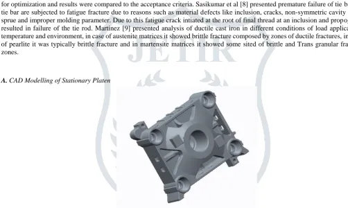
A. CAD Modelling of Stationary Platen
Fig. 1. CAD model of Existing Stationary Platen
B. Design modification done on original model
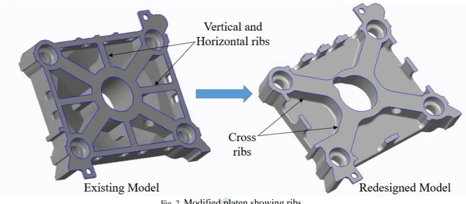
For the purpose of design improvement of the 910 Ton Stationary platen it was proposed to make it flat and also injection uni t entrance hole diameter has also been increased.
Fig. 2. Modified platen showing ribs
In this platen the dome shape of the front plate has been made flat with dimensions 120 mm in model and the extrude patterns on dome shape were removed for distribution of stresses. On top and bottom of the platen there were four pockets of dimensions 100*130 mm they are been modified and only two pockets of sizes 525*130 mm are been made with only one connecting ribs on all four sides for the purpose of lifting the platen while assembling and other maintenance purpose. Table 1 shows some other modified dimension of important parameters.
Table 1. : Comparison of Various Parameters for Existing and Modified Model
Parameters Existing Platen (mm) Modified Platen (mm)
Pads 177 40
Connecting ribs 75 -
Front plate thickness 120 120
Left and right pockets size 100*130 220*130
Top and bottom Pocket size 100*130 525*130
C. Finite Element Analysis of Modified Stationary Platen
Keeping all the boundary conditions of symmetry, displacement constraints and force conditions on the quarter section of platen the results of modified platen are as follows:
1) Minimum mold condition
Fig. 3. Total Deformation & Maximum Principal Stress of Modified platen for Minimum mold condition
2) Long horizontal mold condition
Fig. 5. Total Deformation & Maximum Principal Stress of Modified platen for Long Vertical mold condition
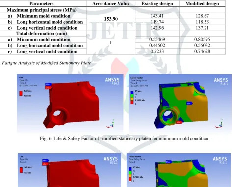
The results of maximum permissible stress and total deformation for 910 tonnage capacity stationary platen is shown in Table 2 for existing and modified design. From Table 2 it is concluded that all values are within permissible limit.
Table 2. Comparison of existing and modified stationary platen for static analysis
Parameters Acceptance Value Existing design Modified design
Maximum principal stress (MPa)
153.90
a) Minimum mold condition 143.41 128.67
b) Long horizontal mold condition 119.74 118.53
c) Long vertical mold condition 142.96 137.21
Total deformation (mm)
1
a) Minimum mold condition 0.55469 0.80595
b) Long horizontal mold condition 0.44502 0.55032
c) Long vertical mold condition 0.5233 0.74628
D. Fatigue Analysis of Modified Stationary Plate
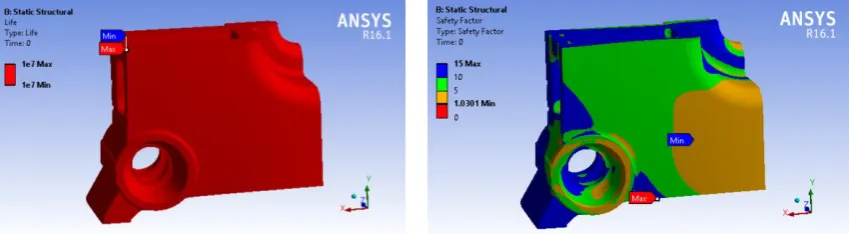
Fig. 6. Life & Safety Factor of modified stationary platen for minimum mold condition
Fig. 8. Life & Safety Factor of modified stationary platen for Long vertical mold condition
The comparison between existing model and modified model of life and safety factor are shown in table 3 for all three mold conditions and is concluded that stationary platen will achieve maximum life.
Table 3. Comparison of Life and Safety Factor of Existing Model and Modified Model
Mold condition Existing Model Modified Model
Life (minimum number of
cycles)
Safety factor (minimum)
Life (minimum number of
cycles)
Safety factor (minimum)
a) Minimum 1.00E+07 1.3635 1.00E+07 1.3302
b) Long Horizontal 1.00E+07 1.6331 1.00E+07 1.2977
c) Long Vertical 1.00E+07 1.3679 1.00E+07 1.0301
III.CONCLUSION
1. The Stationary Platen is redesigned and analyzed for operating condition using conventional finite element software (ANSYS) and stresses and deformation are obtained within acceptance criteria, also the fatigue analysis also showed that platen will achieve its maximum life.
2. Due to redesign and modification of stationary platen substantial reduction in weight about 388 kg is obtained and also design is improved and made flat box like structure.
REFERENCES
[1] Rosato Dominick, Rosato Donald V and Marlene G, Injection molding hand book, 3rd edition, Kluwer academic publishe 1980.
[2] Athaliye A.S Injection molding handbook, P. Noordho_ Ltd., Groningen, The Netherlands, 1963. [3] Johannaber F. Injection molding machines, Hanser/ Gardner publications 1985.
[4] ASM Handbook, Vol.15: Casting, USA, ASM International, 10th edition.
[5] S. H. Sun, Optimum topology design for the stationary platen of a plastic injection Machine, Computers in Industry 55 (2004) 147_158.
[6] J.Li, G.Cai, Y. Zhang, Topological Optimization Method and Its Application Research In The Rear Platen 3-D Structure Design, IEEE conference on Cybernetics and Intelligent Systems, Chengdu, Sept. 2008.
[7] Huang Hai-bo, Xue Dong-hui. "Topology optimization of the movable platen of plastic injection machine using optistruct." 2011.
[8] Dheeraj Mandliya, Yogesh Agrawal, G. V. R Seshagiri Rao, Design Optimization of stationary platen of plastic injection molding machine using FEA, International Journal of Engineering Sciences and Research Technology, ISSN: 2277-9655, May 2014.
[9] R. Bin, Z. Shuyou, T. Jianrong, Structural Scheme Optimization Design for the Stationary Platen of a Precision Plastic Injection Molding Machine, Chinese journal of mechanical engineering, 2014,27(2).
[10] E. Zhang, Finite Element Analysis and Topology optimization design for front platen of injection molding machine, Applied Mechanics and materials 365366(2013) 42-46.
[11] N. Patel, M. Chauhan, FEA and topology optimization of 1000T clamp cylinder for injection Molding Machine, Procedia Engineering 51(2013) 617-623.
[12] C. Sasikumar, S. Srikanth, S.K. Das, Analysis of premature failure of a tie bar in an injection molding machine, Engineering Failure Analysis 13 (2006) 1246_1259.
[13] R.A Martinez, Fracture surfaces and the associated failure mechanisms in ductile iron with di_erent matrices and load bearing, Engineering Fracture Mechanics 77 (2010) 2749_2762.
[14] O. Asi, Failure analysis of a crankshaft made from ductile cast iron, Engineering Failure Analysis 13(2006) 1260-1267. [15] ASM Hand book of fatigue and fracture, Vol.19, USA, A.S.M. international, 1996.