Analysis of Exhaust System of Diesel Engine
Using Solid Works Modelling
1
Sinha Yashpalsinh L,
2Imran molvi
1M. Tech Student, 2Assistant Professor 1,2 Department of Mechanical Engineering,
1,2 Parul Institute of Engineering and Technology, Parul University, Vadodara, India
Abstract: Exhaust emission is main reason of health problems now a days because about 71% of pollution is generated by the exhaust of vehicles only. Normally exhaust gases contains hydro carbons and carbon monoxides. This harmful gas can damage environment and health problems are generated. In this study the vibration and noise generated by the exhaust gases and exhaust noise is mainly focused. In this study the exhaust muffler vibration and backpressure analysis are carried out using solid works modelling.
KEY WORDS
:
exhaust system, diesel engine, three -wheeler engine, solid works, analysis I. INTRODUCTIONIn recent years key focus point is to reduce the air pollution and noise caused by the exhaust. Muffler is one part which focuses in reducing the noise and vibration caused by the back pressure exerted by the gases.[11]
Muffler is not main part of the exhaust system used to reduce the pollution. It is used to reduce the noise and vibration generated by the exhaust gas pressure. The key functions of automotive engine exhaust system are to carry out hot NOx from engine to atmosphere and significantly absorbing noise from the engine through muffler, quickly and efficiently.
II. EXHAUST SYSTEM
An Automobile exhaust system is usually Pipe used To draw burned gases away after a controlled combustion process inside an engine. The entire system draws burnt gases from the engine and includes one or more exhaust pipes.
An exhaust system must be designed to carry out the flue gases to the environment at sufficiently low pressure and maximum noise cancellation. The exhaust system serves two main functions. It reduces the noise generated by the high-pressure gases. The other purpose is to funnel the exhaust safely away from the vehicle. exhausts produce six gases as emissions; of the six, three are toxic (CO, CO2, NOx). Exhaust emissions system is the only means of channeling those ham full fumes. These exhaust gases then pass through a catalytic converter which removes unhealthy elements including carbon monoxide and hydrogen monoxide which are converted into inert gases.
III. OBSERVATION
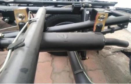
From the field reports coming to Atul auto Ltd. It is found that the number of complaints is coming from the customers. Main parts of failure are related to muffler assembly.it is seen that muffler and exhaust pipe flange are getting broken in running condition. Another problem found from the field report is muffler bracket are getting damaged eventually damaging the muffler.
Fig. 1. exhaust system engine assembly IV. EXHAUST BACK PRESSURE [11]
Back pressure is the pressure exerted by the exhaust gas to overcome resistance of exhaust system. Muffler is designed to minimize the resonance developed by the exhaust gases by trapping them between platinum rhodium or platinum polonium plates. These plates restrict the free flow of the gases increasing the back pressure inside the exhaust system. [11]
BACK PRESSURE LIMITS: [9]
Every engine has its own back pressure limit depending on the manufacturers design. After the specified back pressure limits of the engine more fuel consumption and reduction in efficiency is developed. Depending on the engine size the back-pressure values are shown in table:
Table 1 Recommended back pressure limits [8,9] Engine size (HP) Back pressure limit
Up to 50 40 kPa
50 to 500 20 kPa
Above 500 10 kPa
V. FAILURE OF MUFFLER PARTS
From the field reports it is found that the number of muffler failure reports are coming to Atul auto Ltd. Are regarding the muffler and chassis failure from the m our research is concerned to muffler failure only.
Main muffler failure reports coming from the field are as below:
1) Muffler and exhaust pipe joining flange is getting separated causing the excessive noise coming from the engine. 2) Engine vibration is more at the idling speed of 1400 rpm in diesel engine.
3) Catalytic converter pipe is breaking near the flange side is also problem faced by the customers. 4) And, the bracket mounting the muffler to the chassis is also get broken.
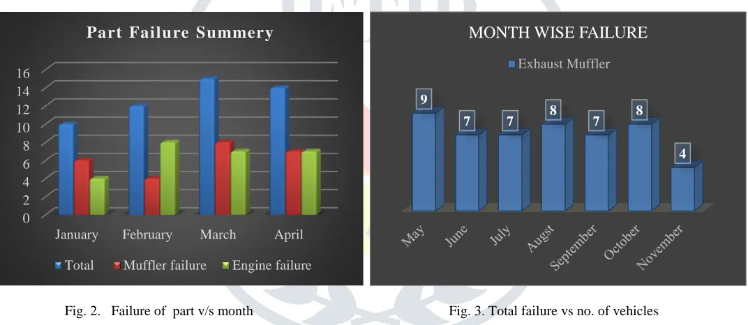
Fig. 2. Failure of part v/s month Fig. 3. Total failure vs no. of vehicles
Out of the that the number of failure reports coming from the field during the month of march three different location the failure reports were 10,7,5 respectively. similarly, the number of failure reports from the different location are shown in chart.[9] VI. SOLIDWORKS SIMULATION
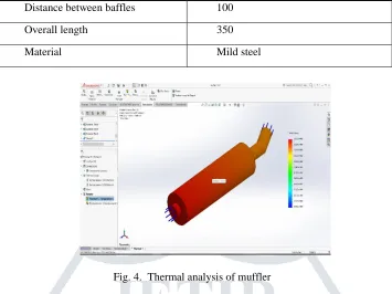
1)Thermal analysis: From the field reports “Flash Reports” as discussed above the failure complains are coming from the customers are increasing day by day this research is carried out to reduce the exhaust failure and improve the life cycle on the part. Thermal analysis is carried out. Boundary condition for the analysis carried out in solid works simulation are 298 k temperature surrounding, inlet temperature of 850 and outlet temperature of 320 k is considered
Table 2. Specification of muffler
Name Specification
Inlet pipe diameter 60 Type of muffler Reactive Outlet pipe diameter 36
Number of holes 60
Distance between baffles 150 0 2 4 6 8 10 12 14 16
January February March April
Part Failure Summery
Total Muffler failure Engine failure
9
7 7 8 7 8
4
MONTH WISE FAILURE
Distance between baffles 100
Overall length 350
Material Mild steel
Fig. 4. Thermal analysis of muffler
2) PRESSURE FLOW ANALYSIS: In the study the pressure flow analysis using the Finite volume method is carried out under which the muffler design is carried out for back pressure exerted by the muffler assembly.
Proposed design of the Muffler used in pressure analysis is shown in fig..C1 is the front expansion chamber with perforation at the piping and C2 is the extension provided for the noise and cancellation. For the research purpose the dimension is changed to reduce the back pressure exerted by the engine.
Fig. 5. Pressure analysis of muffler
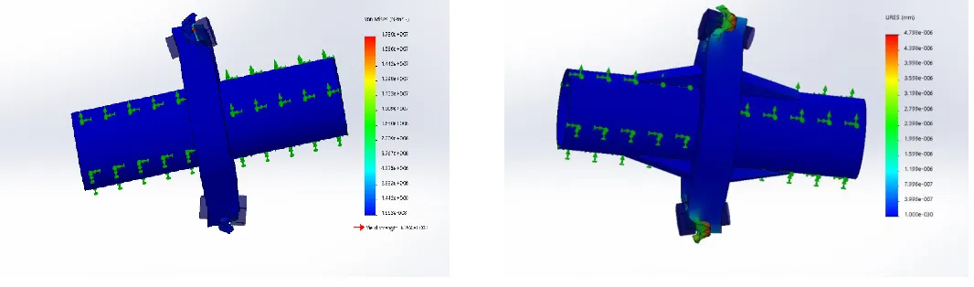
3) vibration analysis: Vibration analysis of the muffler is carried out using the solid works flow simulation.in which the Vibration at the idling speed of 1400 to 1500 rpm is found in existing system are considered and accordingly the Resonance of vibration.
At the nodal frequencies of 1500 Hz and rpm of 1400 – idling RPM of the vehicle vibration analysis is carried out using FFEplus solver for analysis from the analysis it is found that at the working condition of 1200 to 1400 rpm the brackets joints with the muffler body are more prominent to failure.
Another study is conducted under low frequency value of 500 Hz. In this study as seen in Fig. maximum and minimum working boundary condition was between 3.775e-001 to 3.771e-001 Ampres.
CORRECTIVE TESTING
From the analysis it is found that main reason of muffler failure is caused by the improper welding parameter used at the vender end. as seen in the diagram the thermal stresses generated at the weld portion is causing the damage to the muffler assembly.
Other modification also applied to the exhaust pipe mounting.in diesel engine the main ailure problem is generated by the crake generation in muffler body and break of the exhaust pipe. exhaust pipe flange till now is mounted at an angle was carried out at 90 degree from the horizontal axis now the mounting angle of the flange is changed to 25 degree from the horizontal axis to reduce the vibration occurring from the engine generated by the flange mounting this modification is implemented by the r&d department and it is in trial phase. new mounting position of flange is as shown in figure.
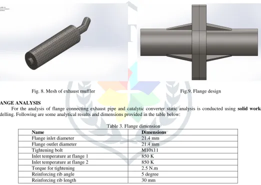
For the analysis exhaust muffler is mashed in total 40748 nodes to analysis the vibration causing the failure of part from the analysis it is observed that at idealing rpm of 1400 rotation exhaust flanges are getting broken from the exhaust mounting side due to the high vibration.
Fig. 8. Mesh of exhaust muffler Fig.9. Flange design FLANGE ANALYSIS
For the analysis of flange connecting exhaust pipe and catalytic converter static analysis is conducted using solid works modelling. Following are some analytical results and dimensions provided in the table below:
Table 3. Flange dimension
Name Dimensions
Flange inlet diameter 21.4 mm
Flange outlet diameter 21.4 mm
Tightening bolt M10x11
Inlet temperature at flange 1 850 K Inlet temperature at flange 2 850 K
Torque for tightening 2.5 N.m
Reinforcing rib angle 5 degree
Reinforcing rib length 30 mm
Fig.10. Flange without reinforcement Fig. 11 Flange with reinforcing material
Without using the flange where the temperature goes to 850 k and tightening torque of 2.5 N.m portion of the flange is getting damaged from the mounting side of the flanges. This can be validated by static analysis carried out at 850 K temperature and atmospheric pressure condition.
Whereas compare to reinforcing material with inclination angle of 5 degree and 30 mm in length is provided in second study. This reinforcement has reduced the failure of Flange by the means of reduced stress concentration in the flange mounting bolts. CORRECTIVE TESTING
From the analysis it is found that main reason of muffler failure is caused by the improper welding parameter used at the vender end. as seen in the diagram the thermal stresses generated at the weld portion is causing the damage to the muffler assembly.
For the analysis exhaust muffler is mashed in total 40748 nodes to analysis the vibration causing the failure of part from the analysis it is observed that at idealing rpm of 1400 rotation exhaust flanges are getting broken from the exhaust mounting side due to the high vibration.
1. Modification on Exhaust pipe mounting
Fig. 12. Exhaust mounting before Fig. 13. After modification mounting of the exhaust pipe
From the analysis it is observed that the exhaust pipe mounting can be modified to insulate the vibration of the exhaust mounting. For the insulation of vibration New clamp implemented for exhaust pipe mounting instead of mounting bracket .by implementing the new clamp with absorbing pad has reduced the vibration of exhaust mounting by 10 percent in vehicle.
2. Catalytic converter mounting position
Till now the engine and catalytic converter are mounted to each by the steel plate with bolts. This mounting was transferring the engine vibration to the chassis and creating the vehicle vibration. To reduce the vehicle vibration mounting position of the catalytic converter changed as shown and, we have started using the OEM catalytic converter. Due to the change in design the life and durability of product is increased.
3. Flange Design
Another main problem that is irritating the customers is the exhaust flange is getting broken during the working condition. This was creating the unnecessary noise and vibration from the vehicle to reduce that problem we have introduced the flange with the reinforcements. This reinforcement is providing the support to the flange in high loading condition.
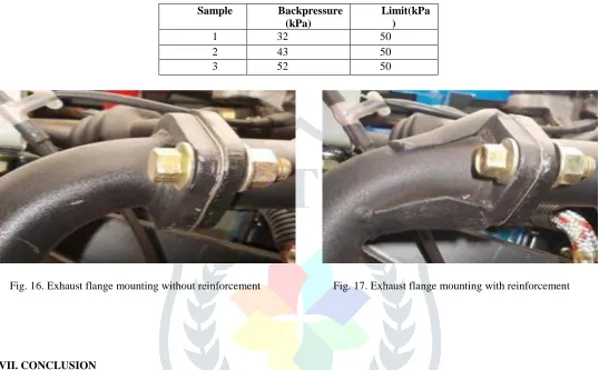
To find out the problem is caused by the back pressure or not we have conducted back pressure analysis in plant and following results are found.[7]
Table 3. back pressure reading Sample Backpressure
(kPa)
Limit(kPa )
1 32 50
2 43 50
3 52 50
Fig. 16. Exhaust flange mounting without reinforcement Fig. 17. Exhaust flange mounting with reinforcement
VII. CONCLUSION
1) By changing the mounting of the exhaust pipe assembly with rubber pad vibration is eliminated by 10%.
2) Flange with reinforcement can reduce the problem causing the separation of exhaust pipe and catalytic converter. 3) Vibration from the engine is grounded by removing the clamp from the catalytic converter and changing to OEM converter.
VIII. ACKNOWLEDGEMENT
Very thankful to Atul auto Ltd. For giving opportunity for completing Industrial Defined Project And faculties of Parul Institute of Engineering and Technology. I am very thankful to our senior engineer at company and internal and external faculties for the project guidelines.
REFERANCE
[1] C., P. Om Ariara Guhan; G, Arthanareeswaran; K, N Varadarajan; S, Krishnan. 2018. Exhaust System Muffler Volume Optimization of Light Commercial Vehicle Using CFD Analysis.Journal of sound vibration. elsevier 5 :(8471–8479).
[2] Dr. Igor Anilovich, Michael Schellong,John W. Siekkinen. 2010. exhaust system performence dignosis.IFAC Symposium Advances in Automotive Control. 6:105-110
[3] D.T. Oloruntoba, A.P.I. Popoola. 2014. Effect of coating on induced thermal and tensile stress on fracture of exhaust pipe material. engineering failure analsis. Elsevere
[4] Jingxiang Li, ShengdunZhao. 2014. Optimization of valve opening process for the suppression of impulse exhaust noise ELSEVIER. Journal of vibration analysis. 38:24–40
[5] S.L.Shinde, Mr. Sanchit Babarao Dhotre1. 2016. Analysis of Automotive Exhaust Muffler Silencer Using FEA and Experiment. IJFEAT.10-14
[6] N.S.Ahirrao, Dr.S.P.Bhosle , Dr.D.V.Nehete. 2018. Dynamics and Vibration Measurements in Engines.Procedia manufacturing. Science direct. 20 :434–439
[8] Shital Shah, Saisankaranarayana Kuppili, Kalyankumar Hatti, Dhananjay Thombare. 2010. A Practical Approach towards Muffler Design,Development and Prototype Validation. SAE international. 32:0021
[9] P. Srinivas, Venkata Ramesh Mamilla, G. Lakshmi Narayana Rao, Sowdager Moin Ahmed. 2016. Design and Analysis of an Automobile Exhaust Muffler. Research gate.american institute of science.1:10-15
[10] Ovidiu Vasile,Gilbert-Rainer Gillich. 2012. Finite Element Analysis of Acoustic Pressure Levels and Transmission loss With Muffler. Advances in Remote Sensing, Finite Differences and Information Security. reseaarch gate. 20:132
[11] Murari Mohon Roy, Mohammad Uzzal Hossain Joardder and Md. Shazib Uddin. 2010. Effect of Engine Backpressure on the Performance and Emissions of a CI Engine. Jordanian International Mechanical Engineering Conference.
[12] M. Philip Hubert Smith.1976. Exhaust and Intake Systems. 3rd illustrated reprint. [13] M. O. R. Marsiial. 1897. Exhaust Muffler for Engines.
[14] Alfred, Samuel. 2018 Researches on the Physics behind cooking as a pastime, 20 June 2017. [Online]. Available: https://www.quora.com/What-are-the-dangers-of-continuing-to-drive-a-car-with-an-exhaust-pipe-that-is-rusted-through.
[Accessed 25 october 2018].