Volume 6, Issue 4 [April 2017] PP: 20-27
Analysis Of Structural and Thermal Characteristics Of Disc
Brake With Circular / Oval Shaped Holes For Two Wheeler
1
S.Radhika,
2Dr.S.Sathiyamurthy,
1
P.G. Student, M.E.(CAD), Sri Ramanujar Engineering College, Chennai-127, (Tamilnadu)
2Professor, Sri Ramanujar Engineering College, Chennai-127, (Tamilnadu)
ABSTRACT- In this paper study has conducted on oval grooved and circular grooved disc brake rotor of passenger vehicle with full load of capacity. The study is more likely concern of heat and temperature distribution on disc brake rotor. Thermal analysis has been carried through the heat transfer analysis where to predict the worst case scenario and temperature behaviours of disc brake rotor. Further, finite element analysis, ANSYS software has been used in order to identify the temperature distributions and behaviours of disc brake rotor in steady state responses. The results have been compared for better justification. Thus, the results provide better understanding on the thermal characteristic of disc brake rotor and assist the automotive industry in developing optimum and effective disc brake rotor in two wheeler.
KEYWORDS- Disc brake, Circular hole, Oval hole, ANSYS, Temperature distribution.
I.
INTRODUCTION
1.1 ABOUT THE DISC BRAKE
A brake is a device by means of which artificial frictional resistance is applied to moving machine member, in order to stop the motion of a machine. In the process of performing this function, the brakes absorb either kinetic energy of the moving member or the potential energy given up by objects being lowered by hoists, elevators etc. The energy absorbed by brakes is dissipated in the form of heat. This heat is dissipated in the surrounding atmosphere to stop the vehicle, so the brake system should have following requirements: The brakes must be strong enough to stop the vehicle with in a minimum distance in an emergency. The driver must have proper control over the vehicle during braking and vehicle must not skid. The brakes must have well anti fade characteristics i.e. their effectiveness should not decrease with constant prolonged application. The brakes should have well anti wear properties.
Brake technology, just like suspension technology and fuel-system technology, has come a long way in recent years. What began in the '60s as a serious attempt to provide adequate braking for performance cars has ended in an industry where brakes range from supremely adequate to downright phenomenal.
One of the first steps taken to improve braking came in the early '70s when manufacturers, on a widespread scale, switched from drum to disc brakes. Since the Commercial vehicles have been a crucial part of our industrial landscape for hundreds of years. Majority of a vehicle's stopping power is contained in the front wheels, only the front brakes were upgraded to disc during much of this period.
Since then, many manufacturers have adopted four-wheel disc brakes on their high-end and performance models as well as their low-line economy TRUCKS. The development of friction brakes in motor vehicles began with the use of wood and leather as friction material.
II.
EXPERIMENTAL WORK/ METHODOLOGY
2.1 THE DISC BRAKE
The following methodology is adopted in the paper to meet the above mentioned objective. Import the geometry of disc brake to ANSYS
Meshing of the geometry using tetra mesh in ANSYS Applying material properties, boundary conditions Performing Thermal and Structural response analysis.
2.2 MATERIAL PROPERTIES
Thermal Conductivity = 52e-3 W/mm0K Specific Heat = 447 J/kg 0K
Poisson’s Ratio = 0.27
2.3 ELEMENT DESCRIPTION
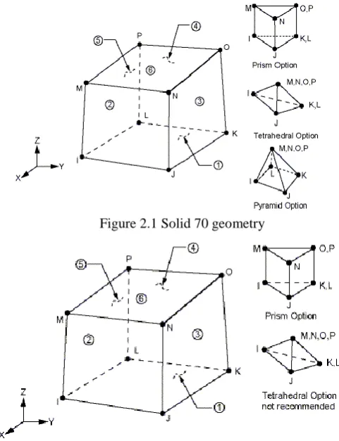
Thermal element: SOLID70 Element DescriptionSOLID70 has a 3-D thermal conduction apability.The element has eight nodes with a single degree of freedom, temperature, at each node. The element is applicableto a 3-D, steady-state or transient thermal analysis. The element also can compensate for mass transport heat flow from a constant velocity field.
Structural element: SOLID185 Element DescriptionSOLID185 is used for 3-D modeling of solid structures. It is defined by eight nodes having three degrees of freedom at each node: translations in the nodal x, y, and z directions. The element has plasticity, hyper elasticity, stress stiffening, creep, large deflection, and large strain capabilities. It also has mixed formulation capability for simulating deformations of nearly incompressible elasto- plastic materials, and fully incompressible hyper elastic materials.
Figure 2.1 Solid 70 geometry
Figure 2.2 Solid 185 geometry
2.4 FINITE ELEMENT ANALYSIS
The analysis is done in ANSYS by taking the Brake Efficiency of 30% and hence the distributions of braking torque between the front and rear axle is 70:30
Thus Load Calculations: Load = 520103.52 N
Pressure = load/Area=1 MPa
Temperature = 1000C
Convection =300E-6 W/mm2 0K
Bulk Temperature = 500C
The procedure for doing analysis is as follows:
First thermal analysis is performed by importing geometric model from ANSYS and applying SOLID70 as
element assigning material properties: young’s modulus as 1.9e5 N/mm2, poisson’s ratio as 0.27, and thermal expansion as 10.8e-6. Applying displacement constraints and pressure as 1Mpa. Then browse .RthFile from thermal Analysis and solved to get the von-misses stresses.
2.5 GEOMETRIC MODELING
ANSYS itself is used for modeling of disc brake rotor with oval and circular hole. Then the model is imported in to ANSYS for doing analysis.
Figure 2.3: Geometric model of disc brake with circular hole
Figure 2.4: Geometric model of disc brake with oval hole
III.
RESULTS AND DISCUSSION
3.1 RESULTS OF DISC PLATE WITH CIRCULAR HOLE:
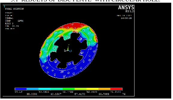
Figure 3.1.Nodal temperature of disk brake with circular hole
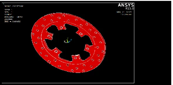
Figure 3.2.Deformation of disk brake with circular hole
Figure 3.2.Shows Total Deformation of Disc Brake. Deformation is 0.144402 mm
Figure3.3. Von-mises stress of disk brake with circular hole
Figure3.3. Shows minimum and maximum Vonmises Stress distribution with Circular hole. Minimum value is 0.030533 MPa and Maximum value is 370.653 MPa.
Figure 3.4. Body temperature of disc plate with circular hole
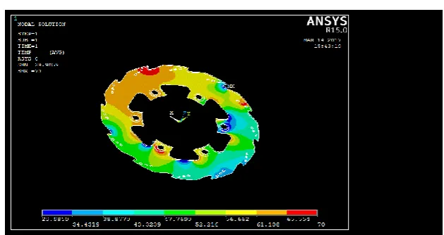
Figure 3.5.Nodal temperature of disk brake with oval hole
Figure 3.5.Shows Minimum and Maximum Temperature distribution with oval hole. Minimum value is 29.9859oC and Maximum value is 70oC.
Figure 3.6.Deformation of disk brake with oval hole
Figure 3.6.Shows Total Deformation of Disc Brake. Deformation is 0.14252 mm.
Figure 3.7. Von-mises stress of disk brake with oval hole
Figure 3.7.Shows minimum and maximum Vonmises Stress distribution with Oval hole. Minimum value is 0.001445 MPa and Maximum value is 191.521 MPa.
Figure 3.8. Body temperature of disc plate with oval hole
Table 3.1.Nodal temperature, deformation and von-mises stresses in the brake Parameters Disc Plate With Circular
Holed
Disc Plate With Oval Holed
Nodal Temperature (oC) 76 70
Deformation (mm) 0.144402 0.14252
Von-mises stress(MPa) 370.653 191.521
3.3 EXPERIMENTAL RESULTS:
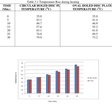
Table 3.1 Shows the temperature distribution of disc plate during heating.
Table 3.1 Temperature Rise during heating TIME
(Min.)
CIRCULAR HOLED DISC PLATE TEMPERATURE (OC)
OVAL HOLED DISC PLATE TEMPERATURE (OC)
0 5 10 15 20 25 30
35.0 43.1 48.7 57.6 63.1 74.0 79.9
35.0 41.4 46.9 55.2 61.0 69.5 73.2
Figure 3.10.Experimental setup
The above experimental setup is used for investigating the temperature generation and temperature distribution of both circular and oval shaped holes disc plates. The values are noted and tabulated below.
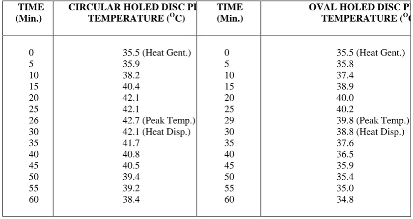
Table 3.2 Experiment results of both disc plates
TIME (Min.)
CIRCULAR HOLED DISC PLATE TEMPERATURE (OC)
TIME (Min.)
OVAL HOLED DISC PLATE TEMPERATURE (OC)
0 5 10 15 20 25 26 30 35 40 45 50 55 60
35.5 (Heat Gent.) 35.9
38.2 40.4 42.1 42.1
42.7 (Peak Temp.) 42.1 (Heat Disp.) 41.7 40.8 40.5 39.4 39.2 38.4 0 5 10 15 20 25 29 30 35 40 45 50 55 60
35.5 (Heat Gent.) 35.8
37.4 38.9 40.0 40.2
39.8 (Peak Temp.) 38.8 (Heat Disp.) 37.6 36.5 35.9 35.4 35.0 34.8
Table.3.2. Shows the temperature generation and temperature dissipation of both circular and oval holed disc plates. From this it concluded the oval holed disc plate having better heat distribution and dissipation.
IV.
CONCLUSION
In this paper, the Thermal and Structural analysis of disk brakes with circular and oval Hole has been performed. The effect of hole with circular and oval shapes is examined. From results we can say that all the values obtained from the Thermal analysis are less than their allowable values. Hence the brake disk design is safe based on the temperature criteria. Comparing the circular and oval holed disc plates, the thermal results obtained from analysis to conclude which is the best possible combination for the present application.
REFERENCES
[1] Yogesh H. Mishra and Vikas R. (2015), ‘Design And Optimisation Of Disc Brake Rotor (For Two Wheeler)’. International Engineering Research Journal, Vol.1, No.1, pp.288-300.
[2] Lakshmi Narayanan V. and Ranganath lolla (2015), ‘Reverse Engineering of Motorcycle Rear Disc Brake System’. International Journal for Research in Applied Science & Engineering Technology, Vol. 3, No.4, pp.321-327.
[3] Mostafa M. Makrahy, Nouby M. Ghazaly, Abd El-Gwwad A.R., Mahmoud K.R. and Ali M. Abd-El-Tawwab (2013), ‘Optimization of a New Wedge Disc Brake Using Taguchi Approach’. International Journal of Modern Engineering Research, Vol. 3, No. 6, pp-3461-3465.
Streamlining For Cooling Improvement in Ventilated Brake Disc Using CFD As Design Tool’. Journal - The Institution of Engineers, Malaysia, Vol. 72, No.3, pp.27-36.
[5] Mesut Duzgun, (2012), ‘Investigation of thermo-structural behaviors of different ventilation applications on brake discs’. Journal of Mechanical Science and Technology, Vol. 26, No.1, pp.235-240. [6] Kapil Shelar, and Mahesh Chopade. (2015), ‘Investigation for Thermal Performance of Ventilated Disc
Brake Rotor using CFD’. International Engineering Research Journal, Special Issue. 2, pp.211-216. [7] Manjunath T.V., and Suresh P. (2013), ‘Structural and Thermal Analysis of Rotor Disc of Disc
Brake’. International Journal of Innovative Research in Science, Vol. 2, No.12, pp.7741-7749.
[8] Rajagopal T., Ramachandran R., James M. and Soniya Chandrakant G. (2014), ‘Numerical Investigation Of Fluid Flow And Heat Transfer Characteristics On The Aerodynamics Of Ventilated Disc Brake Rotor Using CFD’. THERMAL SCIENCE, Vol. 18, No.2, pp.667-675.
[9] Radhakrishnan C., Yokeswaran K., Vengadeshprasadh M. and Vishnuhasan A. (2015), ‘Design And Analysis Of Disc Brake With Titanium Alloy’. International Journal of Innovative Science, Vol. 2. No.5, pp.1044-1050.
[10] Rakesh Jaiswal, Anupam Raj Jha, Anush Karki, Debayan Das, Pawan Jaiswal, Saurav Rajgadia and Ankit Basnet. (2016), ‘Structural And Thermal Analysis Of Disc Brake Using Solidworks And Ansys’, International Journal of Mechanical Engineering and Technology, Vol. 7, No.1, pp.67-77.
[11] Sanket Kothawade, Aditya Patankar, Rohit Kulkarni and Sameer Ingale. (2016), ‘Determination Of Heat Transfer Coefficient Of Brake Rotor Disc Using CFD Simulation’, International Journal of Mechanical Engineering and Technology, Vol. 7, No.3, pp.276–284.
[12] Sasikumar M. (2014), ‘Design and Thermo-Structural Analysis Of Disc Brake. International Journal in Physical & Applied Sciences, Vol. 1, No.03, pp.11-16.
[13] Deepak Biradar M. R., Chopade S. and Barve B. (2014), ‘Experimental Analysis and Investigation for Thermal Behavior of Ventilated Disc Brake Rotor’. International Journal for Scientific Research & Development, Vol. 2, No.7, pp.390-395.
[14] Shelar Kapil, Chopade Mahesh and Valavade A. P. (2015), ‘Investigation for Flow through the Ventilated Disc Brake Rotor using CFD’. International Journal of Thermal Technologies, Vol.5, No.2, pp.100-105.
[15] Adam Adamowicz and Piotr Grzes. (2011), ‘Influence of Convective Cooling on a Disc Brake Temperature Distribution during Repetitive Braking’. Elsevier, Vol.31, pp.2177-2206.
[16] Zhongzhe Chi, Greg F. Naterer and Yuping He. (2008), ‘Effects of Brake Disc Geometrical Parameters And Configurations On Automotive Braking Thermal Performance, CSME, Vol. 32, No.2, pp.313-324. [17] Sam Charles M. and Devaprasad M.E. (2016), ‘Development Of Brake Pad Using Orange Peel
Reinforcement Polymer Composite’, Elsevier, Vol. 3(5), No.5, pp.29-41.
[18] Praveena S., Lava Kumar, and Sreekanth Reddy S. (2014), ‘Modeling and Structural Analysis of Disc Brake’, Elsevier, Vol. 3, No.10, pp.16501-16509.
[19] Mostafa M. Makrahy, Nouby M. Ghazaly, Abd El-Gwwad A.L., Mahmoud K.R. and Ali M. Abd-El-Tawwab. (2013), ‘ Optimization of a New Wedge Disc Brake Using Taguchi Approach’, International Journal of Modern Engineering Research, Vol. 3, No.6, pp.3461-3465.
[20] Swapnil R. and Bhaskar D.P. (2014), ‘Design and Analysis of Disc Brake, International Journal of Engineering Trends and Technology’, Vol. 8, No.4, pp.165-167.
[21] Anurag Patel and Ankur Malviya. (2015), ‘Thermal and Structural Analysis using FEA on Pillar Vans Type Ventilated Disc Brake Rotor’, International Journal for Scientific Research & Development, Vol. 3, No.10, pp.863-867.
[22] Baron Saiz C., Ingrassia T., Nigrelli V. and Ricotta V. (2015), ‘Thermal stress analysis of different full and ventilated disc brakes’, Elsevier, Vol. 34, pp.608-621.
[23] Akshay Pophale, Marne R.A. (2016), ‘Ansys Analysis Of Braking Rotor Of Two Wheeler’. International Journal of Advanced Engineering Research, Vol. 2, No.3, pp.56-59.
[24] Vijay Kumar B., Pavan Kumar B., Manjunatha, Mayur D. and Shivaramakrishna A. (2016), ‘Finite Element Analysis of Two Wheeler Disc Brake Rotor’. Imperial Journal, Vol. 2, No.4, pp.928-933. [25] Shah E Alam, Yuvraj Vidhyadhar, Prashant Sharma, Abhishek Jain (2015). ‘Thermal Analysis of disc
Brakes Rotor’. Journal of Information Sciences and Computing Technologies, Vol. 3, No.2, pp.196-200. [26] Vishal asokan, Arshad Mohammed Gani, Vimal M., Mohammed nooh muballigh A. and Muthu