e-ISSN: 2278-067X, p-ISSN: 2278-800X, www.ijerd.com
Volume 12, Issue
6(
June2016), PP.18-25
High Speed Area Efficient Radix-2 Fast Fourier transforms using
Signed and Complex Number
Kunwar Ved Pratap Singh Parihar and Prof. Monika Kapoor
MTech. Scholar, Assistant Professor, Electronics & Communication Department, Lakshmi Narain College of Technology, Bhopal, (M.P) [India]
Abstract: with the advent of new technology in the fields of VLSI and communication, there is also an ever
growing demand for high speed processing and low area design. It is also a well-known fact that the chip area and maximum combinational path delay (MCPD) unit forms an integral part of processor design. Due to this regard, high speed and low area architectures become the need of the day. A fast Fourier transform (FFT) is any fast algorithm for computing the DFT. The development of FFT algorithms had a tremendous impact on computational aspects of signal processing and applied science. The decimation-in-time (DIT) fast Fourier transform (FFT) very often has advantage over the decimation-in-frequency (DIF) FFT for most real-valued applications, like speech/image/video processing, biomedical signal processing, and time-series analysis, etc., since it does not require any outputreordering.Index Terms: FFT, Decimation in Time, Decimation in Frequency, real Value data
I.
INTRODUCTION
The discrete Fourier transform (DFT) is an important tool in many branches of science and engineering [1] and has been studied extensively [2]. For many practical applications, it is important to have an implementation of the DFT that is as fast as possible. In the past, speed was the direct consequence of clever algorithms [2] that minimized the number of arithmetic operations. On present day general-purpose microprocessors, however, the performance of a program is mostly determined by complicated interactions of the code with the processor pipeline, and by the structure of the memory. Designing for performance under these conditions requires an intimate knowledge of the computer architecture. In this paper, we address this problem by means of a novel adaptive approach, where the program itself adapts the computation to the details of the hardware. We developed FFTW, an adaptive, high performance implementation of the Cooley-Tukey fast Fourier transform (FFT) algorithm [3], written in C. We have compared many C and FORTRAN implementations of the DFT on several machines, and our experiments show that FFTW typically yields significantly better performance than all other publicly available DFT software.
driven to a high clock frequency, which is O(log N) times the data sample frequency. In the application specific parallel or pipelined processor approach, the required operations are performed at the clock frequency equivalent to the sample frequency, and this approach usually consumes less power.
II.
FAST FOURIER TRANSFORM
Before going further to discuss on the FFT and IFFT design, it is good to explain a bit on the fast Fourier transform and inverse fast Fourier transform operation. The fast Fourier transform (FFT) and inverse fast Fourier transform (IFFT) are derived from the main function which is called Discrete Fourier Transform (DFT). The idea of using FFT/IFFT instead of DFT is that the computation of the function can be made faster where this is the main criteria for implementation in the digital signal processing. In DFT the computation for N-point of the DFT will calculate one by one for each point. While for FFT/IFFT, the computation is done simultaneously and this method saves quite a lot of time. Below is the equation (2.2) showing the DFT and from here the equation is derived to get FFT/IFFT function.
N k j N n
e
n
x
k
X
2 1 0)
(
)
(
(1) X (k) represent the DFT frequency output at the k-the spectral point where k ranges from 0 to N-1. The quantity N represents the number of sample points in the DFT data frame.The quantity x (n) represents the nth time sample, where n also ranges from 0 to N-1. In general equation, x (n) can be real or complex.
The DFT equation can be re-written equation (2) into:
nk N N n
W
n
x
k
X
1 0)
(
)
(
(2)The quantity
W
Nnk is defined as in equation (3)N k j nk N
e
W
2
(3) Here is where the secret lies between DFT and FFT/IFFT where the equation (2.4) function above is called Twiddle Factor. This factor is calculated and put in a table in order to make the computation easier and can run simultaneously. The Twiddle Factor table is depending on the number of point use. During the computation of IFFT, the factor does not to recalculate since it can refer to the Twiddle factor table thus it save time since calculation is done concurrently.Inverse Fast Fourier Transform
Inverse fast Fourier transform (IFFT) is used to generate OFDM symbols. The data bits is represent as the frequency domain and since IFFT convert signal from frequency domain to time domain, it is used in transmitter to handle the process.
Table 1: Twiddle factor for 8 point inverse fast Fourier transform IFFT (N=8)
No. W Value
1 0
8
W
12 1
8
W
0.7071+j0.70713 2
8
W
j4 3
8
W
-0.7071+j0.70715 4
8
W
-16 5
8
W
-0.7071-j0.70717 6
8
W
-j18 7
8
IFFT is defined as the equation (4) below:
nk N N
n
W
k
X
N
n
x
10
)
(
1
)
(
(4) Same FFT algorithm can be used to find IFFT function with the changes in certain properties. The changes that implement is by adding a scaling factor of 1/N and replacing twiddle factor value ( ) with the complex conjugate ( ) to the above equation. With these changes, the same FFT flow graph also can be used for the inverse fast Fourier transform. Below is the table 2.2 show the values of twiddle factor for IFFT.
Figure 1: Radix-2 Decimation in Time Domain FFT Algorithm
III.
PROPOSED METHOD
The flow chart of the proposed methodology is shown in figure 3. In this paper we are used three techniques i.e. unsigned multiplier, signed multiplier and complex multiplier. In this figure the two signed and unsigned bit multiplier (i.e. multiplier n-bit, multiplicand m-bit) and final output of the multiplier is n+m bits. All the multiplier is design into two parts i.e. partial product generator and multi operand addition.
Figure 3: Flow Chart of the proposed Methodology
Signed Multiplier:-
Complex Multiplier:-
The FFT algorithms are classified into two broad categories, namely, the decimation-in-time (DIT) and the decimation-infrequency (DIF) algorithms. The proposed radix-2 DIT algorithm is shown in figure 3.
Figure 4: Radix-2 DIT algorithm
Figure 5: Proposed 8-point Radix-2 DIT Algorithm
Figure 6: Proposed 16-point Radix-2 DIT Algorithm
This algorithm decomposes a sequence of DFT into four small DFTs of 1/4 lengths in a recursive manner and their outputs are employed to manipulate several other outputs by which the cost of computation will be reduced. The input data is disintegrated into four small sequences of x (4n + i) where n = 0, 1... N/4-1 and i = 0, 1, 2, 3.
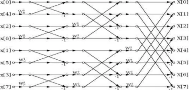
Figure 7: Proposed 32-point Radix-2 DIT Algorithm
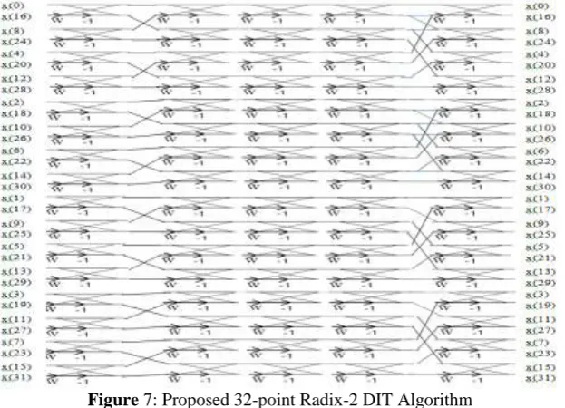
Figure 8: Proposed 9-point Radix-3 DIT Algorithm
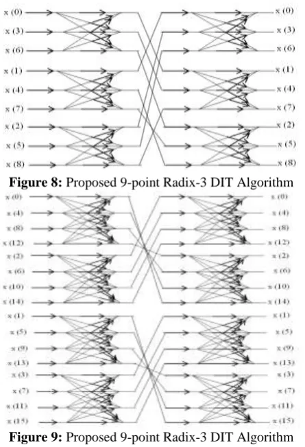
Figure 9: Proposed 9-point Radix-3 DIT Algorithm
IV.
DELAY AND AREA METHODOLOGY
The delay and area evaluation methodology considers all gates to be made up of AND, OR, and Inverter (AOI), each having delay equal to 1 unit and area equal to 1 unit. We then add up the number of gates in the longest path of a logic block that contributes to the maximum delay. The area evaluation is done by counting the total number of AOI gates required for each logic block.
Table 1: Delay and Area calculate in basic block of FFT
Table 2: Computational Delay of Mult-add And Add-mult Operations
V.
SIMULATION RESULT
All the designing and experiment regarding algorithm that we have mentioned in this paper is being developed on Xilinx 6.2i updated version. Xilinx 6.2i has couple of the striking features such as low memory requirement, fast debugging, and low cost. The latest release of ISETM (Integrated Software Environment) design
Adder Block Delay Area
XOR 3 5
2:1 MUX 3 4
Half Adder 3 6
Full Adder 6 13
Architecture TMA TAM TAM- TMA % Difference 8-bit
Pramod Kumar Meher et al. [1] 8.345 8.967 0.622 6.9% Proposed Design 8.048 8.343 0.295 3.5% 16-bit
Pramod Kumar Meher et al. [1] 9.453 10.321 0.868 8.4% Proposed Design 8.653 9.240 0.587 6.3% 32-bit
tool provides the low memory requirement approximate 27 percentage low. ISE 6.2i that provides advanced tools like smart compile technology with better usage of their computing hardware provides faster timing closure and higher quality of results for a better time to designing solution. ISE 6.2i Xilinx tools permits greater flexibility for designs which leverage embedded processors. Also included is the newest release of the chip scope Pro Serial IO Tool kit, providing simplified debugging of high-speed serial IO designs for Virtex-2p FX and Virtex-2p LXT and SXT FPGAs. With the help of this tool we can develop in the area of communication as well as in the area of signal processing and VLSI low power designing.
Table III: Comparison result for existing algorithm and proposed algorithm Radix-2 DIT Algorithm for N=8
Parameter Number of Slice Number of LUTs MCPD (nsec)
Proposed Design (unsigned) 96 192 15.548
Proposed Design (signed) 221 387 15.137
Radix-2 DIT Algorithm for N=16
Parameter Number of Slice Number of LUTs MCPD (nsec)
P. K. Meher et al. [1] - - 21.054
Proposed Design (unsigned) 256 512 19.260
Proposed Design (signed) 573 1000 18.927
Radix-2 DIT Algorithm for N=32
Parameter Number of Slice Number of LUTs MCPD (nsec)
P. K. Meher et al. [1] - - 24.421
Proposed Design (unsigned) 640 1280 22.147
Proposed Design (signed) 1410 2462 22.806
Radix-2 DIT Algorithm for N=64
Parameter Number of Slice Number of LUTs MCPD (nsec)
P. K. Meher et al. [1] - - 29.421
Proposed Design (unsigned) 1536 3072 26.319
Proposed Design (signed) 2431 4063 22.785
Radix-2 DIT Algorithm for N=128
Parameter Number of Slice Number of LUTs MCPD (nsec)
P. K. Meher et al. [1] - - 36.421
Proposed Design (unsigned) 2739 5042 32.895
Proposed Design (signed) 3390 6042 33.806
Table IV: Result for complex number Radix-2 DIT Algorithm for N=8 and N=16
Parameter Number of Slice Number of LUTs MCPD (nsec)
N=8 438 864 24.948
N=16 1168 2304 30.687
Figure 9: Bar graph of the complex number for N=8 and N=16
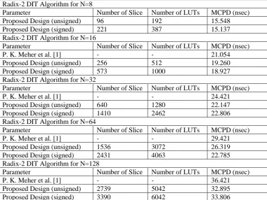
Figure 10: Bar graph of the radix-3 algorithm for N=9
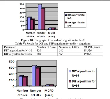
Table V: Result for DIT and DIF algorithm for radix-4 algorithm Parameter Number of Slice Number of LUTs MCPD (nsec)
DIT algorithm for N=16 320 640 18.526
DIF algorithm for N=16 289 568 19.095
Figure 11: Bar graph of the radix-4 algorithm for N=16
VI.
CONCLUSION
The prime objective is to construct a FFT in order to have low power consumption and lesser area. The parameters (i) power consumption (ii) Area occupancy were given due consideration for comparing the proposed circuit with other FFTs. The circuits were simulated using Model-Sim 6.3c and synthesized with Xilinx ISE 14.1.The performance of various 64 point FFT such as Radix-2, Radix-4, split Radix, mixed -radix 4-2, R2MDC and the proposed modified R2MDC were carried out and their performance were analyzed with respect to the number of CLB slices, utilization factor and Power consumption.
REFERENCES
[1] Charles. Roth Jr., ―Digital Systems Design using VHDL‖, Thomson Brooks/Cole, 7th reprint, 2005.
[2] S. S. Kerur, Prakash Narchi, Jayashree C N, Harish M Kittur and Girish V A, ―Implementation of Vedic multiplier for Digital Signal Processing‖, International Conference on VLSI, Communication & Instrumentation (ICVCI) 2011, Proceedings published by International Joural of Computer Applications® (IJCA), pp.1-6.
[3] Himanshu Thapaliyal and M.B Srinivas, ―VLSI Implementation of RSA Encryption System Using Ancient Indian Vedic Mathematics‖, Center for VLSI and Embedded System Technologies, International Institute of Information Technology Hyderabad, India.
[4] Jagadguru Swami Sri Bharati Krishna Tirthaji Maharaja, ―Vedic Mathematics: Sixteen simple Mathematical Formulae from the Veda‖, Delhi (2011).
[5] Harpreet Singh Dhillon and Abhijit Mitra, ―A Reduced-bit Multiplication Algorithm for Digital Arithmetic‖, International Journal of Computational and Mathematical Sciences, Febrauary 2008, pp.64-69.
[6] Sumit Vaidya and Depak Dandekar. ―Delay-power performance comparison of multipliers in VLSI circuit design‖. International Journal of Computer Networks & Communications (IJCNC), Vol.2, No.4, July 2010.
[7] Pramod Kumar Mehe, Basant Kumar Mohanty, Sujit Kumar Patel, Soumya Ganguly, and Thambipillai Srikanthan, “Efficient VLSI Architecture for Decimation-in-Time Fast Fourier Transform of Real-Valued Data”, IEEE Transactions on Circuits And Systems—I: Regular Papers, Vol. 62, No. 12, December 2015.
[8] M. Ayinala, Y. Lao, and K. K. Parhi, ―An in-place FFT architecture for real-valued signals,‖ IEEE Trans. Circuits Syst. II, Exp. Briefs, vol. 60, no. 10, pp. 652–656, Oct. 2013.
[9] Shashank Mittal, Md. Zafar Ali Khan and M.B. Srinivas, ―Area Efficient High Speed Architecture of Bruun’s FFT for Software Defined Radio‖, 1930-529X/07/$25.00 © 2007 IEEE.