Comparative Performance Analysis for Two
Tanks Liquid Level Control System with
Various Controllers using Matlab
Damrudhar M.Tech Student
Electrical Engineering Department
B.I.T Sindri, Dhanbad, Jharkhand India
Dr. D.K. Tanti Associate Professor Electrical Engineering Department B.I.T Sindri, Dhanbad, Jharkhand India
Abstract- Liquid level control in tanks and between tanks are basic industrial problem. Often the tanks are so coupled in interacting and non-interacting way they exhibit non-linear behaviour. This paper deals with the level control of two tank system which are connected in interacting and non-interacting mode to control the level of system. In interacting mode the level of first tank will depend on the level of second tank while in case of non-interacting mode level of first tank is independent of level of second tank. Here comparative analysis of the transient response obtained by different controllers- Conventional controller PID, Feed forward-feedback controller, IMC (Internal Model Controller) and Fuzzy Logic Controller has been done using MATLAB simulation. It has been observed that IMC performs better than other controllers for both interacting and non-interacting mode.
KEYWORDS- Level Control, PID, Feed forward-feedback, IMC, FLC, MATLAB
I.INTRODUCTION
The Control of liquid level in tanks and flow between tanks is the basic problem in process industries. In Process industry the liquid pumped and store in the tank and then pumped to another tank. Many times the liquid will be processed by chemical or mixing treatment in the tanks. The liquid should be processed such that the level of fluid in the tanks must be controlled and flow between the tanks must be regulated [1]. It is essential to understand that how the tank is controlled and how the level control problem solved. Here in this paper performance will be analysed on the basis of characteristics e.g. rise time ( ), settling time ( ), % overshoot
( ).
There are different types of controllers for get the optimized response for any system. PID is one of the effective conventional controller that used from long years back. Ziegler Nichols- tuning method for PID controller is a popular tuning process [2]-[3]. The disadvantage of PID controller is that it is not suitable for higher order nonlinear system. Feed forward controller uses two loops in its structure which helps to minimize interaction coefficient of the system and improve the response [4]. IMC controller is used to minimize the disturbance of the system and to make the system internally stable. IMC gives better result than other implemented controllers [5]. Fuzzy Logic Controller (FLC) is an intelligent controller which uses IF and THEN rule to obtain optimized result. However FLC makes the system little sluggish [8]-[9].
II. MATHEMATICAL ANALYSIS
Here in this work two tanks are connected in interacting and non-interacting manner. Mathematical calculation for both the tank has been done to distinguish interacting and non-interacting connection [2] [6]. A disturbance has also been introduced in the considered system. Disturbance is nothing but an extra input for second tank.
Case I: Two Tank Interacting system
Level of tank 1 is represented by and level of tank 2 is represented by .
Fig.1 Two Tank Interacting tank system with disturbances
Here,
=Volumetric flow rate in to tank 1( )
=Volumetric flow rate from tank 1 to tank 2 ( )
= Volumetric flow rate from tank 2( ) =Height of the liquid level in tank 1 (cm) =Height of the liquid level in tank 2 (cm)
= Cross sectional area of tank 1 ( ) = Cross sectional area of tank 2 (
=Linear resistance of flow from tank 1 through valve 1 (sec/ ) =Linear resistance of flow from tank 2 through valve 2 (sec/ )
For Tank 1:-
By Mass Balanced Equation;
= (1) By Torcilli equation linear resistance to flow is ( ) and the relation between Volumetric flow rate into tank
and linear resistance ( ) can be given as
=( ) (2)
Putting the value of equation (2) in equation (1)
= ( ) (3)
= (4)
For Tank 2:-
By Mass Balanced equation;
(5)
By Torcilli equation linear resistance to flow ( ) through valve 2 and relation between output Volumetric rate ( ) and Linear resistance to flow ( ) can be given as;
(6)
Putting the value of from equation (2) and from equation (6) in equation (5)
(7)
By Laplace transform,
(9)
Where;
Disturbance analysis for two tanks interacting Water Level Tank System will be given as:
(10)
Table.1 Parameters value for two tank
Parameters Value Unit
250
250
0.01
0.01
30 Cm
15 Cm
Using the parameters shown in table 1 the final transfer function for the interacting system will be
(11)
Transfer function for Disturbance will be given as;
(12)
Case II: Two Tank Non- Interacting system
Fig.2 Two Tank Non-Interacting system with disturbance
For Tank 1:
From above figure Mass Balance Equation; (13) By Torcilli equation the relationship between linear resistance of flow through valve 1 and input flow
rate of liquid ( ) will be given as (14)
Putting the value of in equation (13)
(15)
For Tank 2:
By Mass balance equation;
(16) Again by Torcilli equation the relationship between linear resistance of flow through valve 2 and output
flow rate for tank ( ) will be given as follow
(17)
(18)
Using Laplace transform.
(19)
Where;
Using parameters value from table 1 transfer function for non-interacting system will be given as;
III.CONTROLLERS DESIGN
(i)PID CONTROLLER
A PID controller is a controller that includes proportional gain ( ), integral gain ( ), and the derivative gain . Defining u(t) as the controller output, the final form of the PID algorithm is:
Fig.3 General Control Structure of PID
(21)
and have been used for effective performance of the system. Major drawback of this method is that oscillation will be present in the system response.
(ii) FEED FORWARD-FEEDBACK CONTROLLER
Feed-forward controllers are always used along with feedback controller. Feedback controller is used to tracking the change in set point and also minimized the effect of disturbances which is unmeasured in nature and such type of disturbances are always present in the real plant. Conventional feedback control loops can never achieve perfect control. It is difficult for the conventional loops to keep the process output continuously at the desired set point value if the load or set point changes. This is because a feedback reacts only after it has detected a deviation in the value of the output from the desired set point. Unlike the feedback control systems, a feed forward control configuration measures the disturbance directly and takes the control action to eliminate its impact on the process output.
(22)
Where,
_ DC gain of the controller
- Are the time constant of the controller
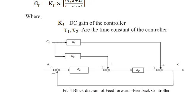
Fig.4 Block diagram of Feed forward –Feedback Controller Where,
G1- transfer function between output and disturbance Gf - transfer function of feed forward controller
Gc - transfer function of PID controller Gp - transfer function of plant
Table. 2 Tuning rule for Feed-forward controller
Sr. No Mode IJ
1 IJ2
1. Lead 1.5 peak time 0.7 peak time
2. Lag 0.7 peak time 1.5peak time
(iii) IMC CONTROLLER
parameter “lem( )” is used to avoid the effect of model uncertainty. The normal IMC design procedure focuses on set point responses but with good set point responses good disturbance rejection is not assured, especially those occurring at the process inputs. A modification in the design procedure is proposed to enhance input disturbance rejection and to make the system internally stable.
Fig.5 Basic Block Diagram Of IMC
(s)= *(s).f(s)={inv[ (s)]}f(s) (23)
Where, f(s) is transfer function for LPF. Used to make the system at least semi-proper. Because Improper system has not stable response.
f(s) =
where, ȜLVDGMXVWDEOHDQGQ WRWDOQXPEHURISROH
Ȝ
IMC design for 2ndorder system:
= (24)
*(s)= *(s). -*(s)=
(25) Since here both poles are in left side of s-plane
*(s)=inv[ -*(s)]=
Since here in this system there are two poles so value of n=2
*(s)
)RUȜ DQGQ
(26)
(iv) FUZZY LOGIC CONTROLLER
value based on linguistic values. In this the input to the fuzzy logic controller is error and change in error; it is then fuzzified and converted to linguistic variables. The rules are framed by trials and error method and thus the desired response is obtained. The IF-THEN rules have been used here. The triangular membership functions for the input and output are chosen and their ranges are split.
Table.3 Rule base array for FLC (25)
E(n)/CE(n) NB N Z P PB
NB NB NB NB N Z
N NB NB N Z P
Z NB N Z P PB
P N Z P PB PB
PB Z P PB PB PB
IV. SIMULATION RESULTS
Fig.6 Comparison of responses for two tank interacting system
for all controllers Fig.7 Comparison of responses for two tank non- interacting system for all controllers
V. PERFORMANCE ANALYSIS
Table.4 and Table.5 describe the performance analysis of all controllers. IMC has least settling time and no overshoot. Hence the IMC control scheme is the best suited for this system as it provides best overall performance.
Table.4 Comparative analysis for two tank interacting system
Controller Rise
Time( )
Settling time( )
%Overshoot
PID 1.24 6.5 12.3
Feed f/w-feedback
5.19 29.08 15.2
IMC 1.77 3.10 0
Table.5 Comparative analysis for two tank non-interacting system
VI. CONCLUSION
It has been observed that IMC controller performs better than other controllers. It has been found out that IMC rejects disturbance and provides a stable system. It has also been shown that non-interacting connection has better performance for different controllers except IMC where interacting and non-interacting both have similar characteristics.
REFERENCES
[1] IEEE sponsored 2ndinternational conference on innovation in Information Embedded and Communication system ICIIECS’15 ”
Comparative study of various level control techniques for a two tank system” Haneema Vargees K PG scholar department of Electronics and Instrumentation Karunya university Coimbtore, India.
[2] Mostafa A.Fellani, Aboubaker M.Gabaj Control Engg. Dept. Faculty of Electronic Technology, Beni-Walid ,Libya. “PID Controller Design for Two Tanks Liquid Level Control System using MATLAB”.
[3] Divya Krishanana, K. Shravanam, P. Harikrishnan PG scholar Dept. of EEE Anna University Regional centr Coimbtore, Tamilnadu. “Simulation of ZN-Tuning method for Adaptive PID controller in Cylindrical Tank Level System Using Lab View”. ISSN 2348-6988. [4] Ashish kumar Singh, Sandeep Kumar Dept. of Electronics and Communication Engg. NIT, Rourkela Odisha. “Comparing The
Performance Analysis Three Tank Level Control System using Feedback and Feedforward –Feedback Configuration.” 2014 IEEE conference on Advance Communication control and computing technologies (ICACCCT).
[5] Dasgupta S.Dept of Electr.Engg. , Jadavpur Univ., Kolkata, India; Sadhu, S;Ghoshal T.K “ Internal Model Control based controller design for a Stirred water tank” India Conference(INDICON), 2010 annual IEEE.
[6] Pravat .B.J, Deo .S.A and Kadu. C.B 1Professor, Department of Instrumentation and control PREC, Loni, Maharashtra, India ME student, Department of Instrumentation and control, PREC, Loni, Maharashtra, India HOD, Department of Instrumentation and control PREC, Loni, Maharashtra, India. “Mathematical Modeling of Interacting and Non Interacting Tank System”
[7] Dazi Li, Fanyou Zeng, Qibing Jin, Lideng Pan Department of Automation, Beijing University of Chemical Technology, Beijing, 100029, PR China. “Applications of an IMC based PID Controller tuning strategy in atmospheric and vacuum distillation units”. Contents lists available at Science Direct Nonlinear Analysis: Real World Applications journal homepage: www.elsevier.com/locate/nonrwa.
[8] Deepa Shivshant Bhandarel and N. R.Kulkarni Ph. D. Student, Department of Electrical Engineering, Modem College of Engineering, Pune University, “Performances Evaluation and Comparison of PID Controller and Fuzzy Logic Controller for Process Liquid Level Control” 2015 15th International Conference on Control, Automation and Systems (lCCAS 2015) Oct. 13-16-2015 in BEXCO, Busan, Korea.
[9] Yan Zhao; Coll of Electr. And Inf. Eng., Shaanxi of science and technol., Xian, china “Research on application of Fuzzy PID controller in Two Container water system control” IEEE conference 2010.
Controller Rise
Time( )
Settling time( )
%Overshoot
PID 1.01 5.86 17
Feed
f/w-feedback 4.05 14.73 11.5
IMC 1.77 3.10 0