IJIRT 147195
INTERNATIONAL JO URNAL OF INNOVATIVE RESEARCH IN TECHNOLOGY197
Review on Performance Analysis of Shell and Tube Heat
Exchanger with Different Number of Baffels
Vikas Koshti
1, Mr. Saumitra Sharma
2 1Research Scholar, Department of Mechanical Engineering Oriental College of Technology, BHOPAL
2Asst. Prof., Department of Mechanical Engineering Oriental College of Technology, BHOPAL
Abstract-Heat exchangers such as shell-and-tube, plate type and finned tube are used in various industries for different applications such as heating, cooling, condensation or evaporation process. The present work review about the numerical investigation of heat and fluid flow in shell and tube heat exchanger with different numbers of baffles on shell side.
Index Terms- S hell and Tube Heat Exchanger, Hot Fluid Outlet Temperature, Cold Fluid Outlet Temperature, Turbulence Eddy Dissipation, Wall Heat Transfer Coefficient, Baffles.
I. INTRODUCTION 1.1 General
Heat transfer device, for example, heat exchangers, boilers, condensers, radiators, heaters, heaters, coolers, and sun based authorities are composed fundamentally based on heat transfer examination. The heat transfer issues experienced practically speaking can be considered in two gatherings: (1) Rating and
(2) Sizing issues.
The rating issues manage the assurance of the heat transfer rate for a current framework at a predetermined temperature contrast. The sizing issues manage the assurance of the measure of a framework so as to transfer heat at a predetermined rate for a predefined temperature contrast.
1.2 Heat Exchanger
A heat exchanger is a gadget that is utilized to transfer warm vitality (enthalpy) between at least two liquids, between a strong surface and a liquid, or between strong particulates and a liquid, at various temperatures and in warm contact. In heat exchangers, there are typically no outside heat and work communications. Run of the mill applications include heating or cooling of a liquid stream of
concern and dissipation or buildup of single-or multicomponent liquid streams.
The warmth exchange surface is a surface of the exchanger focus that is in facilitate contact with fluids and through which warm is exchanged by conduction. That bit of the surface that is in coordinate contact with both the hot and chilly liquids and transfers heat between them is allud ed to as the essential or direct surface. To expand the heat transfer region, extremities might be personally associated with the essential surface to give a broadened, optional, or backhanded surface. These stretched out surface components are alluded to as balances. Therefore, heat is led through the balance and convected (and additionally emanated) from the balance (through the surface region) to the encompassing liquid, or the other way around, contingent upon whether the blade is being cooled or heated. Accordingly, the expansion of blades to the essential surface decreases the warm opposition on that side and along these lines expands the aggregate heat transfer from the surface for a similar temperature distinction. Balances may shape stream sections for the individual liquids however don't separate the (at least two) liquids of the exchanger. These auxiliary surfaces or balances may likewise be presented essentially for basic quality purposes or to give exhaustive blending of a very gooey fluid.
Shell-and-Tube Exchangers
IJIRT 147195
INTERNATIONAL JO URNAL OF INNOVATIVE RESEARCH IN TECHNOLOGY198
A wide range of inner developments are utilized inshell-and-tube exchangers, contingent upon the coveted heat transfer and pressure drop execution and the strategies utilized to diminish warm worries, to counteract spillages, to accommodate simplicity of cleaning, to contain working pressures and temperatures, to control consumption, to suit very awry streams, et cetera. Shell-and-tube exchangers are arranged and developed as per the broadly utilized TEMA (Tubular Exchanger Manufacturers Association) gauges (TEMA, 1999), DIN and different guidelines in Europe and somewhere else, and ASME (American Society of Mechanical Engineers) heater and pressure vessel codes. The three most basic sorts of shell-and-tube exchangers are
(1) Fixed tube sheet outline, (2) U-tube outline, and (3) skimming head compose.
In each of the three sorts, the front-end head is stationary while the backside head can be either stationary or coasting, contingent upon the warm worries in the shell, tube, or tube sheet, because of temperature contrasts because of heat transfer. The chief parts of shell-and-tube exchangers are
Figure 1.1 (a) Shell-and-tube exchanger (BEM) with one shell pass and one tube pass; (b) shell and -tube exchanger (BEU) with one shell pass and two tube passes.
Tubes. Round tubes in different shapes are utilized in shell-and-tube exchangers. Most fundamental are the tube packs {with straight and U-tubes) utilized in process and power industry exchangers . Nonetheless, sine-wave twist, J-shape, L-shape or hockey sticks, and upset hockey sticks are used in cutting edge
nuclear exchangers to oblige extensive warm development of the tubes.
Figure 1.2 Additional tube configurations used in shell-and-tube exchangers
Shells. The shell is a compartment for the shell fluid. Usually, it is cylindrical fit as a fiddle with a circular cross area, although shells of various shapes are used in particular applications and in nuclear heat exchangers to fit in with the tube bundle shape.
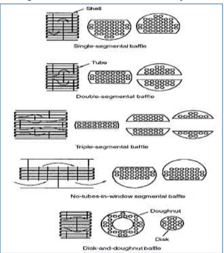
Figure 1.3 Plate baffle types
1.3 Heat Transfer Modes
Heat transfer is the trading of warm vitality between physical frameworks. The rate of heat transfer is reliant on the temperatures of the frameworks and the properties of the mediating medium through which the heat is transferred. The three key methods of warmth exchange are conduction, convection and radiation. Heat transfer will occur toward a path that builds the entropy of the accumulation of frameworks. The three modes of heat transfer are 1. Conduction
IJIRT 147195
INTERNATIONAL JO URNAL OF INNOVATIVE RESEARCH IN TECHNOLOGY199
The conduction mode of heat transport occurs eitherbecause of a trade of vitality starting with one molecule then onto the next, without the actual movement of the molecules, or because of the movement of any free electrons that are available. Hence, this type of heat transport depends intensely on the properties of the medium and happens in solids, liquids and gases if a distinction in temperature exists.
1.4 Laws of Heat Transfer
It is noteworthy to process the measure of vitality being transmitted per unit time, with additionally this needs the utilization of rate figurings . For the mode of heat conduction, the rate equation is identified as Fourier’s law, which is stated for one aspect as
here qx is the heat flux in the x direction (W/m2); k is the thermal conductivity (W/m K), a property of material, and dT/dx is the temperature gradient (K/m).
For convective warmth exchange, the rate condition is given by Newton's law of cooling as
q=h (T_w-T_a)
Where q is the convective warmth motion; (W/m2); (Tw − Ta) is the temperature difference between the wall and the fluid and h is the convection heat transfer coefficient, (W/m2K).
The expansion of vitality in a framework is equivalent to the contrast between the vitality transfer by heat to the framework and the vitality transfer by work done on the surroundings by the framework, that is,
Where Q is the aggregate heat entering the framework and W is the work done on the environment. Since we are occupied with the rate of vitality transfer in heat transfer forms, we can rehash the principal law of thermodynamics as takes after: The rate of increment of the vitality of the framework is equivalent to the contrast between the rate at which vitality enters the framework and the rate at which the framework works on the environment, that is,
Where t is the time.
1.5 Heat Transfer Enhancement
In by and large, enhanced warmth exchange surfaces can be utilized for three purposes:
(1) To make warm exchangers more conservative with a specific end goal to decrease their general volume, and potentially their expense,
(2) To decrease the pumping power required for a given warmth exchange process, and
(3) To expand the general UA estimation of the warmth exchanger.
A higher UA esteem can be abused in two different ways:
(1) To get an expanded warmth conversion standard for settled liquid delta temperatures, or
(2) To diminish the mean temperature contrast for the warmth trade; this expands the thermodynamic procedure proficiency, which can decrease working expenses.
If there should arise an occurrence of gas -side warmth exchange improvement, utilizing extraordinary surface geometries, it very well may be perceived with higher hA per unit base surface region. Clearly, there are three essential methods for finishing this.
1) Upsurge the genuine warmth exchange surface territory (A) per unit volume without uniquely changing the warmth exchange coefficient (h). Plain blade surfaces upgrade warm move in this way. 2) Increase h without apparently evolving A. This is expert by utilizing an extraordinary channel shape, for example, a wavy or ridged channel, which gives blending because of optional streams and limit layer partition inside the channel.
3) Increase both h and A. Intruded on blades (i.e. balance strip and louvered blades) act along these lines. These surfaces increment the compelling surface region, and upgrade warm exchange through rehashed development and pulverization of the limit layers
II- LITERATURE REVIEW
IJIRT 147195
INTERNATIONAL JO URNAL OF INNOVATIVE RESEARCH IN TECHNOLOGY200
Limited works have been achieved in the field offlow distribution within geometrical changes of a tubular heat exchanger.
Improvement of heat transfer through shell and tube exchangers stills taking high consideration by specialists. Ammar Ali Abd et al;2018, explored the impact of shell distance across and tube length on heat transfer coefficient and weight drop for shell agree with both triangular and square pitches. What's more, the impact of astound separating and cutting space on heat transfer coefficient and weight drop were contemplated. Also, standards fouling rates utilized for both shell and tube sides to appraise the decreased heat transfer. Expanding shell distance across with a triangular pitch and draw through floating head recorded 3% expanding in heat transfer coefficient for just 0,05m expanding in shell width. While 2.8% expansion in heat transfer coefficient for shell side by 0.05m expanding in shell distance across with split-ring floating head and square pitch. Heat transfer coefficient for shell side decreased by 15.15% by expanding bewilder space by 0.2 from shell breadth and the weight drop by 41.25%. Expanding slicing space from 15% to 25% reductions heat transfer coefficient by 5.56% and the weight drop lessened by 26.3%. Expanding tube length by 0.61m prompts upgrade the heat trans fer coefficient by 31.9% and weight drop by 14.11% for tube side. For shell side, expanding tube length by 0.61m gives 2.2% expanding in heat transfer coefficient and 21.9% expanding for weight drop. Fouling obstruction change on shell side demonstrates a high impact on heat transfer more than same rate change on the tube side.
Sunil Shinde and Umesh Chavan, 2018, manages the numerical and exploratory examination of heat and liquid stream in shell and tube heat exchanger with ceaseless helical confuses on shell side. Seven helix points, in particular 10°, 19°, 21°, 25°, 30°, 38°, and 50° are explored numerically by displaying a full length persistent helical confounded shell-and-tube heat exchanger for various mass stream rates and delta temperature conditions. Results uncovered that the bigger helix edges (30°, 38° and 50°) adds to bring down heat transfer and lower weight drop, and littler helix edges (10°, 19°and 21°) brought about higher heat transfer and additionally higher weight drop. The trials were completed on shell and tube
heat exchanger for helical baffles with 25° helix point and results were contrasted and segmental baffles. The conduct of the liquid inside the inward flow arrangement of a shell and tube heat exchanger is perplexing because of the impact of numerous variables. The stream conveyance affects the execution of fluidic device, for example, shell and tube heat exchangers. The non-consistency of the stream conveyance diminishes the effectiveness of the procedure. O. Labbadlia et al 2017, thought about four kinds of course of action. The outcomes got are in great concurrence with those of the writing. The got results demonstrate that the course of action of the tubes impacts the stream dispersion. It was inferred that the stream conveyance of 60° game plan displays better consistency contrasted with the regular course of action (90°) by 21%. The 45° course of action gives great consistency of weight dissemination contrasted with alternate game plans.
III-CONCLUSION
After literature it is saw that only few investigators have carried out numerical analysis of heat and fluid flow in heat exchanger in shell and tube heat exchanger utilizing full-length show. Likewise, no significant endeavors have been completed to examine the impact of number of puzzles on the execution of heat exchanger.
REFERENCES
[1] Ammar Ali Abd, Mohammed Qasim Kareem and Samah Zaki Naji, 2018, “Performance Analysis of Shell and Tube Heat Exchanger: Parametric Study”, Case Studies in Thermal Engineering.
[2] Bao-Cun Du, Ya-Ling He, Yu Qiu, Qi Liang, Yi-Peng Zhou; 2018, “Investigation on heat transfer characteristics of molten salt in a shell-and tube heat exchanger”, International Communications in Heat and Mass Transfer 96 (2018) 61–68 [3] J. wen, X. Gu, M. Wang, Y. Liu, S. Wang,
“Multi-parameter Optimization of Shell-and-Tube Heat Exchanger with Helical Baffles Based on Entransy Theory”, Applied Thermal Engineering (2017)
IJIRT 147195
INTERNATIONAL JO URNAL OF INNOVATIVE RESEARCH IN TECHNOLOGY201
with different baffle configurations”, AppliedThermal Engineering (2018)
[5] O. Labbadlia, B. Laribi, B. Chetti, P. Hendrick, Numerical Study of the Influence of Tube Arrangement on the Flow Distribution in the Header of Shell and Tube Heat Exchangers, Applied Thermal Engineering (2017),
[6] Pranita Bichkar, Ojas Dandgaval, Pranita Dalvi, Rhushabh Godase and Tapobrata Dey, 2018, “Study of Shell and Tube Heat Exchanger with the Effect of Types of Baffles”, Procedia Manufacturing 20 (2018) 195–200
[7] Sunil Shinde, Umesh Chavan, 2018, “Numerical and experimental analysis on shell side thermo -hydraulic performance of shell and tube heat exchanger with continuous helical FRP baffles”, Thermal Science and Engineering Progress 5 (2018) 158–171
[8] Xinting Wang, Nianben Zheng, Zhichun Liu, Wei Liu, 2018, “Numerical analysis and optimization study on shell-side performances of a shell and tube heat exchanger with staggered baffles”, International Journal of Heat and Mass Transfer 124 (2018) 247–259