A Complete Denture By Rapid Prototyping with
Reverse Engineering Approach
Mohd Nazri Ahmad1,a, Mohammad Khalid Wahid2,b, Nurul Ain Maidin3,c, Mohd Hidayat Ab Rahman4, Mohd Hairizal Osman5, Izzati Fatin Alis@Elias6
1,2,3,4,5,6 Faculty of Mechanical and Manufacturing Engineering Technology,
Universiti Teknikal Malaysia Melaka, Hang Tuah Jaya, 76100 Durian Tunggal, Melaka, Malaysia
a[email protected], b[email protected], c[email protected]
Abstract-- This paper presents a denture fabrication process by implementing the techniques used in the addictive manufacturing which is 3D printing technology involving reverse engineering method. A three dimensional scanner was used to obtain the surface data of the complete partial denture model that received from the dental clinic. The scanned data was refined using the Geomagic Studio and then converted to STL format for CAD and 3D printing application. The complete dentures design was converted to STL format for production of the product using the Projet HD 1000 machine which is one of the rapid prototyping (RP) technique. Cold cure acrylic resin (VERTEX, Castavaria) was used as the denture material on the gum section. On the teeth section, the composite resin will be applied to add an aesthetic value to the part. Then, the final dentures were polished and tested on an edentulous model to test the bite and adaptability. The finished denture has been test to ensure the adaptability and comfortability. Thus, the user felt comfort while tested the printed denture. The method of fabrication by addictive manufacturing is much faster compared to traditional method. The time taken to complete the denture is 5 hours. Otherwise by conventional method consumed about 15 hours. The result for the denture has been checked to ensure satisfactory and good accuracy. Unlike the traditional method of fabrication, this research has potential to reduce fabrication period of time and make it easier to replace a new set of denture that had been broken.
Index Term-- Denture, Rapid Prototyping, 3D Printer, Reverse Engineering
INTRODUCTION
3D printing technologies that also synonyms with rapid manufacturing are technologies that emerging as one of the advanced tools nowadays. The 3D printing technologies are processed that realizing the digital design into the physical part. It starts from a digital 3D model, then it will be converted become thin layers by a specific software and tools. Rapid manufacturing was defined as the producing of end-use products by using additive manufacturing techniques and also can be defined as the direct production of finished goods from rapid prototyping (RP) devices [1,2]. Reverse engineering is a process by which the design of a product is analyzed or recreated using a physical part as a starting point [3]. In reverse engineering, it requires to analyzing the product mechanism, reviews all the design ideas and technology that been used to establish the product with a systematic approach.
There are several types of denture available nowadays based on the patient conditions. denture has been classified into removable or full denture, fixed denture and implant supported overdentures [4-6]. The complete dentures are full-coverage oral prosthetic devices that replace a whole arch of missing teeth and to restore normal contour, functions, comfort, and speech [7]. The complete dentures also have an effect on speech sounds by altering the dimensions and morphology of the mouth. The insertion of complete dentures plates often leads to speech alteration before using the denture [8]. An implant-supported denture is a kind of denture that is supported via and attached to implants. It has unique attachments that in shape over the implants, like a snap fastener or a press-stud. Bruxers, bone-grafted individuals and irradiated cancer patients were excluded, as were patients with a history of failed implant-supported fixed prostheses [9].
Nowadays the fabrication technique can be classified into two type, which are conventional fabrication technique and advanced fabrication technique. The fabrication of complete dentures traditionally contains a sequence of complex technical procedures. Those procedures include two impressions for each jaw and a dental technician cast a model of the mouth using impression from the dentist [10]. Over the last decade computer-aided design, computer aided manufacture (CAM) and rapid prototyping techniques have been employed in dentistry, but predominantly to the manufacture of crown and bridges [11-13]. Digital Denture Manufacturing is capable of making complex, customer-specific products immediately, and eliminates time-consuming intermediate steps such as the manufacture of the molds [14]. Lately, many dentists were used additive manufacturing techniques in the fields of oral maxillofacial surgery simulation and implantology. Sun, J. et .al [15] discusses the application of rapid prototyping in prosthodontics which are fabrication of wax pattern for the dental prosthesis, dental (facial) prosthesis mold fabrication, dental metal prosthesis fabrication, and zirconia prosthesis fabrication. Some users could benefit from this new technology through various forms of dental prosthesis production. Traditional prosthodontic practices could also be changed by rapid prototyping techniques in the near future.
a master model at all, the 3D printed master model as in Figure 1 may be used for conventional aspects of the fabrication of a restoration, such as adding a veneering material [16]. In advance patient’s teeth data may be digitally archived, and only printed while needed, then easing storage requirements.
Fig. 1. 3D printed teeth and data from an intra oral scanner
Mainly, this study will focus on developing and fabricate a removable complete denture (RCD) by using reverse engineering approach. The RCD will be fabricated with 3D
printing technology application. The manual method or conventional style will be taking a long period of time to produce. The user having difficulty without teeth in their daily basis due to the long process of fabricating. Furthermore, the manual method involves too many steps, such as making an impression, master model, wax up, mould casting, divesting, preparation and lastly veneering. The reverse engineering method will replicate the existing dentures and the part will be produced by using 3D printing technology. The aims of this research are to apply the reverse engineering technique in setting the denture scanned data (point cloud) by a 3D scanning method, and replicate a set of the denture by 3D printing technology.
RESEARCH METHODOLOGY
The main objective of the research is to replicate a set of entire denture by using 3D printing method and to implement reverse Engineering method to fabricate a prototype of complete denture. The complete denture will undergo the reverse engineering method before fabricating it with the help of 3D printing technology. Methodology can be divided into five levels which are identify product, 3-D scanning(digitizing), 3D model editing, 3D printing, and fabricate it completely with flashing technique of manufacturing denture. The flow of method in developing a denture by rapid prototyping technique is shown in Figure 2.
Fig. 2. The flow of method to develop a denture by 3D printer.
The type of reverse engineering equipment that was used in this experimental is Rexscan scanner that is furnished in the rapid prototyping laboratory. After scanning has been finished, the subsequent method of the technique is 3D model
component. Next method is RP technique using 3D printing liquid based. Then, the denture will go through flasking method to make a finished goods denture.
a. Scanning Process
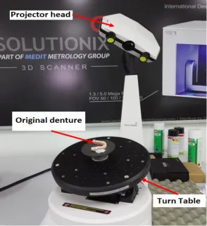
In the 3D scanning method, there are two types of method classification which are contact method and non-contact method. The most suitable method for this project is non-contact method. The 3D scanner machine that been used is Solutionix Rexscan CS2+ which accuracy up to 30 microns. Rexscan CS2+ offers ease of scanning path generation. Commonly, when complex scans conducted, it required various scanning paths, the Rexcan offers the flexibility of the scanning path generation making it easy for you to create your own scanning path, allowing repeat data collection on
various object sizes and shapes. Since the complete denture has some contour that complex, the Solutionix Rexscan CS2+ can offer better accuracy. The scanner can work in automatic mode with only a single click of a button and fast scanning process. The effective single click away to actively synchronize the model and camera perspectives, enabling users to recognize any scanning function and to add extra scans where it can be needed. Before performing the 3D scanning process cleaned the surface of the research product. The surface of the product must clear from oil, dust or any substance that will offer bad result during scanning. The process started when the part had been placed or clamped well on the turn table and by only one click on the interfaced software, the process began. Figure 3 shows Rexscan 3D scanner has been used to scan the original denture.
Fig. 3. Rexscan 3D scanner built with blue light technology.
b. 3D Editing Process
Fig. 4. Post-processing phase of a denture scanned data (a) cloud point (b) polygon phase (c) color region
The first step in the 3D editing process is the point phase. In this phase, the noise reduction process needs to be done to reduce the point of scanned data. The step in the point phase began with reduction of noise of the uniform sample and lastly compute the wrap process. The point of the scanned data reduces to 143899 after done the point phase. Then, proceed the editing phase to polygon phase. In the polygon phase, the polygon models are constructed. They are controlled to meet the requirement of the application. In order to get an acceptable result, few steps need to be done. The first process is the open manifold process. Second is filling the hole process which fills the gap hole on the surface and checks the triangle of the surface. The last process is repaired intersection and relax polygon. The number of the triangle of the part was reducing after completing this phase. The last phase of 3D editing phase is shape phase. In this phase, it shows quadrilateral patches that represent the segmentation of the product shape. Each of the patches is laid with multiple resolution grids and a NURBS surface was fitted to each patch. After completing this phase, the NURBS surface can
be exported to STL, IGES or STEP file based on the application.
RESULT AND DISCUSSION
a. Post Processing
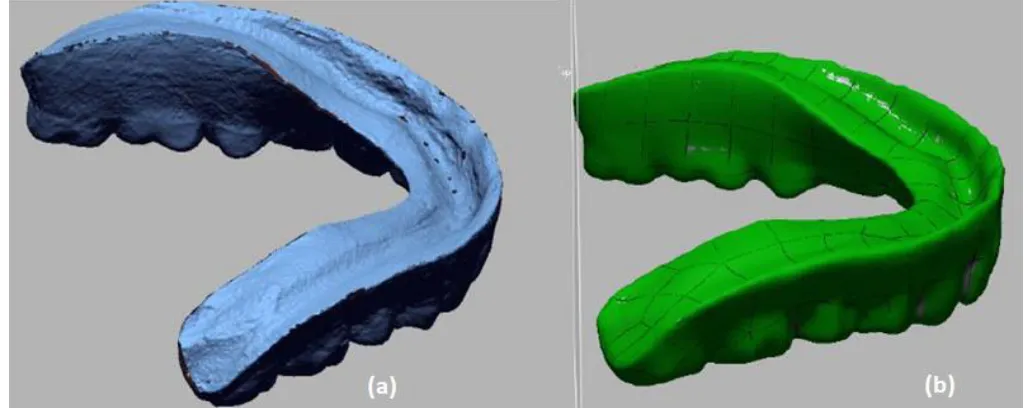
Post Processing is the most crucial phase in reverse engineering method. Raw scanned data need to be transferred into solid NURBS data for the printing process. Usually, the raw scanned data format is in STL and the complete NURBS data is in IGS format. The number scanned data triangle will be reduced in each phase. The raw scanned data number of the triangle is 333513 and after completed NURBS data is 91804. The total number of the triangle being reduced is 241709. The reducing number of the current triangle would make IGES data in smaller point and easy to print. In Figure 5(a) shows the picture of the raw scanned data and Figure 5(b) for finish edited after the NURB surfacing process.
Fig. 5. (a) Scanned data (b) NURB surface data
b. Fabrication Process
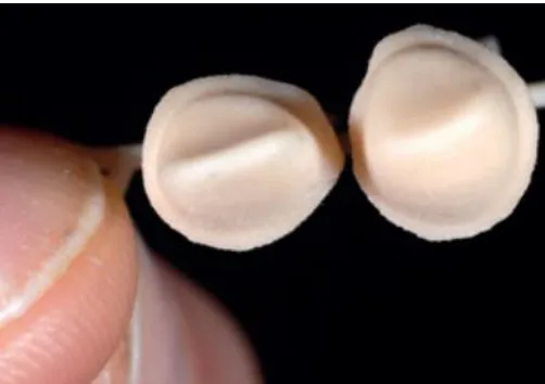
The result of complete denture that using 3D printing method is shown in Figure 6(b). While, Figure 6(a) shows the denture made by conventional method. The printed denture has
through finishing process before fitting on dedicated user mouth.
Fig. 6. A partial denture (a) conventional method (b) rapid prototyping method (3D Printer-ProjectHD 1000)
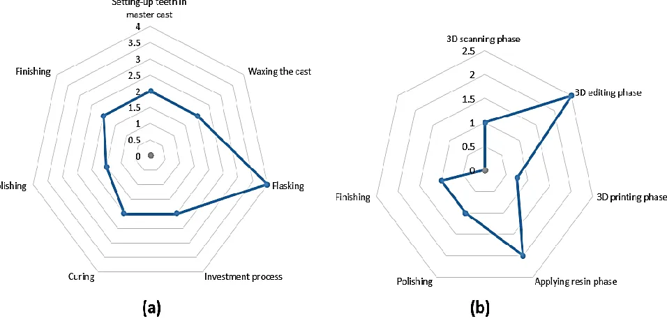
Based on data observation at the dental laboratory, the conventional denture replacement cycle time has been estimated. The estimated time taken is based on trained technician cycle time data. The total time required for conventional complete denture replacement is 15.5 hours. Figure 7(a) shows the estimated time of fabrication using conventional method and Figure 7(b) shows the estimated
time of fabrication by reverse engineering technique. The result shows that by using reverse engineering method, the estimated time taken is 8.25 hours. The reverse engineering method offers a faster way of producing complete denture replacement. It saves about 30% of the time from the conventional method.
c. Inspection and Deviation Analysis
Geomagic Control Software helps to determine the comparison accuracy between the actual parts. The method that is used in the software is a 3D comparison and 2D comparison. The 3D comparison method is used to check and
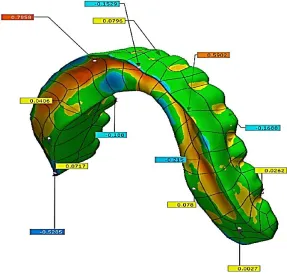
compare the overall surface of the part. The generated result will show the standard deviation comparison, RMS, tolerance, maximum and minimum value. In the 3D comparison result, the tolerance has been set ± 0.15 mm. The ± 0.15 mm is the range tolerance for dental part [17]. The result is shown in Figure 8 below.
Fig. 8. Deviation in color mapping
The values of deviation of printed denture are shown in color mapping as in Figure 7 above. It shows that the part comparison indicates with several region colour. The green region contour shows that both comparison data is in the tolerance of ± 0.15 mm. The yellow region color shows that the part comparison has minor over tolerance. The critical over tolerance is red region colour. The blue region indicates the surface that below tolerance and the light blue region is
minor under tolerance. Table 1 shows the inspection result of printed denture. The value of average, standard deviation and variance are 0.0517, 0.1531 and 0.0234 respectively. Based on the result, it shows that 80.764% of the data compared is within the tolerance which is a good result. Only 19.236 % of the part is out of the tolerance and 15.1283 % is over tolerance.
Table I
Inspection result (unit in mm)
Min. Max. Avg. RMS Std. Dev.
Var. +Avg. -Avg. In Tol.(%)
Out Tol.(%)
Over Tol.(%)
Under Tol.(%)
d. Fitting Process
In order to determine the 3D printed denture is fit same like the original denture, testing on the user is needed. Client of complete denture was agreed to test the 3D printed denture.
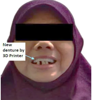
The user literally checks on the product quality and test in terms of comfortably. Usually, the user takes several days to adapt to a new denture. Figure 9 shows the dedicated user has tried the 3D printed complete denture.
Fig. 9. Female user fixed a new denture made by 3D printing method
A sample of data sheet had been developed to analyze the 3D printing complete denture from the client perspective. Based on the data sheet, the client felt satisfied with the 3D printed complete denture. The rating score is 63 % of the total score. The result of the datasheet is shown below in Table 2.
Table II
Fitting Result (1: Very Poor, 2: Poor, 3: Average, 4: Good, 5: Very Good)
No. Inspection Ratings
1 Arch form align 3
2 Arch size align 3
3 Residual ridge fit 3
4 Residual ridge contour comfort 2
5 Maxillary Tuberosity gap 4
6 Frenum attachment fit 4
7 Overall Comfortability 3
Based on the result obtained, the data comparison from original complete denture STL data and 3D printed part STL data were about 80.764 % in tolerance range. It shows that the accuracy of the scanned data that being print is exceptional with high accuracy. The 3D printer that is used which is Project HD 1000 has great accuracy in printing part. In order to achieve an optimized result, the scanning process must be done perfectly. Scanner with the higher precision needed to achieve the maximum result. Furthermore, the aligning process of scanning data also affects the surface
the resin was applied thin and precise without exceed the dental tolerance.
CONCLUSION
Based on the research conducted, the 3D printing method helps to save 30% fabrication time of a denture. The surface quality of the 3D printed part also present vast quality, the dedicated customer satisfied during the fitting test. The conventional complete denture procedure is up seven steps, while by using reverse engineering approach only used six steps. The reverse engineering approach helps to the obtained great accuracy on the part. The part that is printed achieved 80% of in-tolerance value compared to the original complete denture.
ACKNOWLEDGMENT
The authors wish to thank Universiti Teknikal Malaysia Melaka (UTeM) for supporting this research. Special appreciation and gratitude to Centre of Research and Innovation Management (CRIM) and Faculty of Mechanical and Manufacturing Engineering Technology for giving the full cooperation towards this research.
REFERENCE
[1] Rudgley M. Rapid manufacturing-the revolution is beginning. Proceedings of the uRapid. 2001 May:441-4.
[2] Wohlers T. State of the Industry and Technology Update. Proceedings of EuroMould. 2003.
[3] Thakare SB, Awate A. Reverse Engineering using CMM and CAD Tool. International Journal of Engineering Research & Technology (IJERT) Vol. 2013 Oct:2278-0181.
[4] Singla S. Complete denture impression techniques: Evidence-based or philosophical. Indian Journal of Dental Research. 2007 Jul 1;18(3):124.
[5] Pahlevan A. A New Design for Anterior Fixed Partial Denture,
Combining Facial Porcelain and Lingual
Metal; PTU Type II. Journal of Dentistry of Tehran University of Medical Sciences. 2005:116-25.
[6] Vecchiatini R, Mobilio N, Barbin D, Catapano S, Calura G. Milled bar-supported implant overdenture after mandibular resection: a case report. Journal of Oral Implantology. 2009 Oct;35(5):216-20.
[7] Memon MR, Ghani F, Shahzad M. Functional assessment of removable complete dentures. Pakistan Oral & Dental Journal. 2013 Dec 1;33(3).
[8] Arafa KA. Effects of different complete dentures base materials and tooth types on short-term phonetics. Journal of Taibah University Medical Sciences. 2016 Apr 1;11(2):110-4.
[9] Bergendal T, Engquist B. Implant-supported overdentures: a longitudinal prospective study.
International Journal of Oral & Maxillofacial Implants. 1998 Mar 1;13(2).
[10] Cunha TR, Della Vecchia MP, Regis RR, Ribeiro AB, Muglia VA, Mestriner Jr W, De Souza RF. A randomised trial on simplified and conventional methods for complete denture fabrication: masticatory performance and ability. Journal of dentistry. 2013 Feb 1;41(2):133-42.
[11] Willer J, Rossbach A, Weber HP. Computer-assisted milling of dental restorations using a new CAD/CAM data acquisition system. The Journal of prosthetic dentistry. 1998 Sep 1;80(3):346-53.
[12] Van Der Zel JM, Vlaar S, de Ruiter WJ, Davidson C. The CICERO system for CAD/CAM fabrication of full-ceramic crowns. The Journal of prosthetic dentistry. 2001 Mar 1;85(3):261-7.
[13] Duret F, Preston J, Duret B. Performance of CAD/CAM crown restorations. Journal of the California Dental Association. 1996 Sep;24(9):64-71.
[14] Chang CC, Chiang HW. Reconstruction the CAD model of complex object by abrasive computed tomography. InProc IEEE/ASME International Conference on Advanced Manufacturing Technologies and Education in the 21st Century, Taiwan 2002 Aug.
[15] Sun, Jian, and Fu‐Qiang Zhang. "The application of rapid prototyping
in prosthodontics." Journal of Prosthodontics: Implant, Esthetic and Reconstructive Dentistry 21, no. 8 (2012): 641-644.
[16] Dawood, A., B. Marti Marti, V. Sauret-Jackson, and A. Darwood. "3D printing in dentistry." British dental journal 219, no. 11 (2015): 521.