Impact Analysis of Compressed Hygroscopic
Particulate Material
Mauricio Aramburo-Londoño, Santiago Pérez-Cardona, Manuela Calle-Escobar, Alejandro Velásquez-López and
Ricardo Mejía-Gutiérrez
Universidad EAFIT, Design Engineering Research Group (GRID), Medell´ın, Colombia Email: {marambu1, sperezca, mcallees, avelasq9, rmejiag}@eafit.edu.co
Abstract— This article presents a dynamic analysis of the behaviour of a sample of hygroscopic particulate compressed material in the context of diverse scenarios of the product’s lifecycle. The analysis is executed using two complementary methods: (a) an experimental study that recreates a particular impact situation in a controlled physical environment, and (b) a static virtual analysis developed under the Finite Element Method (FEM) for the evaluation of vibration effects on the product. The objective of the analysis is to determine, on one hand, the precise compressing pressure that enables the powder to maintain cohesion throughout the handling and transporting stages, and yet be easily disaggregated manually for it to be used as intended in the final stage of its lifecycle. On the other hand, it is expected of both simulations to estimate an incidence in the behaviour of the compressed powder sample derived from its geometric characteristics and its particular handling and transportation situation, with the goal of defining
ideal conditions for the product packaging.
Index Term— Virtual simulation, wave equation, particulate
material, packaging, vibration, impact, transportation,
product lifecycle
I. INTRODUCTION
Aspects such as logistics, transportation and shelf life are not usually what first comes to mind when executing a product design process. However, a thorough procedure must consider these elements in order to guarantee that a particular product will reach the consumer in the way it was originally intended by the designer.
A study on compaction processes in particulate materials is being carried out. In the specific situation that concerns Consequently, the case addressed in this paper assesses the validity and functional pertinence of the design of a geometrical volume composed of a particulate hygroscopic material subjected to compression processes. Therefore, it is of crucial relevance to understand the effect that an eventual impact or vibration might have on the product, given the mechanical properties of the material that has been used.
It is precisely this issue where the interest for the present study was born. It is desired to fore- see the way in which the material behaves under diverse scenarios where it might be subjected to impact or vibration throughout its lifecycle. In this regard, considering that the end product will be transported and displayed in large retail stores, and then transported to the actual usage scenario, and that the product should remain intact during its shelf life, it has
been established that the product might face situations of constant impact (e.g., vibrations during transportation stages) or single impact (e.g., occasional impacts caused by surrounding objects due to poor manipulation).
It is important to note that the characteristics of the object that is being analysed in this study make it particularly susceptible towards damaging through vibration and impact, given that the product is con- formed by compressed powder and the capability of agglomerates of maintaining physical integrity is variable depending on the compression pressure. This, in addition to the known fact that vibrations derived from transport and handling can create a range of unwanted effects on products of diverse nature [1][2], has helped establish a need for focusing the research particularly in the manipulation and transportation of large stacks of the compressed material, and the possible single or multiple vibration-induced impacts that the product might suffer throughout the journey. Ultimately, a thorough understanding of the effects of single impacts and vibrations on compressed powders might conduct to a clearer understanding of the task of creating a safer packaging design in order to avoid such unwanted effects [3], and will also help designers to think about the impact of packaging from a strategic perspective [4].
II. LITERATURE REVIEW
A. Packaging and impact
The role of packaging has become increasingly relevant in the lifecycle of most products, because it has passed from being a merely protective accessory towards converting into a highly strategic element of product development, given that it serves also as an instrument for brand exposure, and in some cases it grants added functionality to a product.
In terms of logistics, specifically, packaging serves as an instrument for optimization of resources, namely space, time and money.
Therefore, it is relevant to understand how pack- aging can be conceived as a means for maintaining product integrity while providing optimal utilization of resources throughout the logistics chain, from the moment the product is packed to the instant in which it reaches the hands of the end consumers.
in which manipulation is required, such as stacking for transport or retail display. As a matter of fact, an improper handling [5] or an inadequate retail display, for instance, can lead to occasional impacts and cause degradation or permanent damage to a product. This is particularly relevant in products such as compressed powders, that are especially prone to suffering permanent damage if handled improperly.
Aside from generic theoretical approaches to the matter [6], product-specific studies have evaluated the damage caused by impact in their products.
The food industry in particular has done extensive research on this field [7] [8], given the susceptibility of food products to suffer damage in different stages of their lifecycle.
A set of studies has also been performed on agglomerates of diverse nature [9] [10], but with no particular attention to packaging. Additionally, the characteristics of the materials involved in these studies performed at this level do not correspond specifically to the materials that concern this study. Therefore, a particular analysis of impact in handling and transportation must be carried out in order to obtain pertinent results.
B. Packaging and vibration
Vibration induced by transportation conditions can generate undesired effects in the products being transported. In fact, efforts have been made towards facilitating the understanding vibration effects in products and its relation with packaging design [11]. Consequently, it is relevant to explore the relation- ships between the transport scenario of the products and the packaging strategies that can prevent said effects.
Focusing the interest towards transportation- specific situations, it becomes evident that the effects of vibration during transport can have a significant impact in the overall product lifecycle. Such is the relevance of said impact that assessments of transport-induced vibrations have been carried out in diverse places of the world, such as Brazil [12], Thailand [13], Japan [14], India [15] and Spain [16]. Rouillard [17] has developed, among several other works related to packaging and transport, a testing environment that aims to reproduce the vibrations generated during transport under diverse conditions and correlate the results to packaging design. Bernad et al [18] have also carried out studies that assess the behavior of stacked packaging units under the effects of vibration derived from transportation conditions, and Lu et al [19] developed an analysis for the study of the correlation between vehicle speed and vibration in truck transport and the likelihood of improving protective packaging with these variables in mind. None of these studies, however, are oriented towards product-specific results, and offer a rather generic approach to the analysis.
For the case that concerns this study, specificity is highly desired, particularly in terms of materials and product types, given the novelty of the material under development and the particularities of its com- position, which make it exceptionally susceptible to severe damage during transport. Certain studies attempt to correlate product-specific conditions with packaging design [20] [21]; the vast majority of these researches are focused on edible goods and particularly fruits, due to the fact that these are highly
susceptible to damage during transport. Although certain insights can be derived from these analyses –particularly in relation to packaging design–, due to the very specific characteristics of the product under question and the lack of information related to similar products, a simulation environment must be developed for the scenario under analysis.
C. Numerical analysis for the study of vibration and impact in transportation
Numerical analysis offers the possibility of evaluating the behaviour of bodies in certain constrained environments through virtual simulation, enabling the prediction of future behaviour, and allowing researchers and designers to gain control over a particular situation.
The use of this method has served a diversity of industries, from the assessment of composite materials [22], to the design of piezoelectric components [23], the evaluation of diverse civil engineering scenarios such as the evaluation of fracture toughness [24] or the collapsing of entire buildings [25], and the design of mechatronic devices [26], among many other applications. Particularly, it has served as a method for assessing the impact of vibration and impact in diverse transportation means. Such is the case of the study proposed by Nelson and Saurenman [27], and Chua et al. [28], in both of which a model for the measurement of noise and vibration in rail transportation systems is developed, particularly focused on its impact in surrounding buildings. However, no further analysis is devoted to the impact caused specifically on transported products.
In certain cases, preserving the integrity of the product during its lifecycle is crucial and, particularly, in transportation and handling, given the fragility of the product itself. Such is the case of edible goods, especially those that are subject of damage through impact, such as fruits and vegetables. Extensive research has been conducted in the assessment of the impact of vibration and handling in the lifecycle of this kind of products [29] [30]. However, although interesting conclusions can be derived from these studies, the effects produced by vibration on the product under analysis in this case study are not similar to those in foods, and the methods to analyse this phenomenon cannot be extrapolated directly.
For the case of granular materials in general and compressed powders in particular, studies are much less widespread. However, numerical analyses have been applied to the assessment of wave propagation in particulate or granulate materials. The works of Harada et al. [31] and Gong et al [32], among others, approach this matter, but with a focus on dynamic situations where the granulate material is loose. It does reference studies performed for static cases, but these are executed at a larger scale, namely geophysics and soil mechanics; therefore, the applicability of such researches to the present case, which implementation occurs at smaller scales, is practically none.
[34], which describes the behaviour of food particulate materials in general. However, as interesting as the results available are, the specificity of the material under question still poses a number of questions that can only be solved through simulation and experimentation.
D. Theoretical Framework
It is important to take into account that the interest of this research is focused on understanding the effects of diverse types of loads inside an object made of compressed granular material. Therefore, the starting point for the development of the analysis is the formulation of the scalar wave equation modelling acoustic wave propagation [35], delimited under the domain Ω3 , with Ω being an arbitrary subset of R2 restricted under the boundary Γ. The wave equation under these conditions is given by the following expression:
( ) ( ) (1)
With the following boundary conditions:
Dirichlet: which will be applied in the bottom surface of the object to be analysed (See Eq. 2).
( ) ( ) (2)
Newman: The present study will develop two different analyses: Vibration and impact. For the case of the virtual simulation the Newman condition will be considered equal to 0, given to the absence of the source (See Eq. 3). This means that the impact to be evaluated is an event of single occurrence. For the physical experiment, however, the impact will be the result of multiple vibration-induced movements, creating a source that will give a value to the Newman boundary condition.
̂ ( ) (3)
For the virtual analysis that will be performed in the present work, Equation 4 lists the initial conditions of the problem.
( ) ( ) ( )
( ) (4)
For Equations (1) to (4), u(x, t) is the pressure, c(x) is the wave speed depending on ( ) Ω, t is the time variable, T is a final time, and f is a load vector.
The mathematical approach that will conduct to the solution of the problem is reduced, by the means of the transformation of its components into the discrete form, to the following expression (See Eq. 5):
̈ (5)
Finally, it is of interest of the research to understand the manifestation of the behaviour of the wave in time. Therefore, it will be necessary to have a discretization of the results in a determined time interval that is of relevance for the particular problem under study.
For such purpose, the study employs the Finite Differences method, which, applied to the wave equation under the set conditions, delivers the following expression (See Eq. 6):
( ) ( )
(6)
The mathematical approach described above will be implemented in the analysis of a case study, which will be detailed in Section IV
III. RESEARCH BACKGROUND
Powdered materials are widespread across different industries such as food, pharmaceuticals, construction and consumer goods. Because of their nature, it is traditional to see these materials being transported and delivered to final consumers in large amounts. In the case of cement or plaster, for in- stance, the materials are packed in sacks of 25 to 50kg after being processed in quarries and mines. The products are then handled and delivered in this shape to the final consumer. (See Figure 1: Scenario1)
Therefore, considering the logistics behind the production and delivery of powdered products in large volumes, it is relevant to pose a number of questions: What is the most efficient way of trans- porting these materials? Is there a better way to deliver them to the final consumer according to their needs? In terms of retail display, can there be a different, more appropriate manner of presenting the products? How does this traditional packaging and display strategy affect a company’s brand identity?
With these and other questions in mind, the present research proposes rethinking the traditional approach towards packaging powders, by incorporating an additional disaggregation of the product’s load in terms of size and shape, based upon the manner in which these products are currently packaged and manipulated.
The proposal, and ultimately the goal of the research, as shown in Figure 1: Scenario 2, is to compress the powdered material, therefore reducing the volume it occupies when packaged, and facilitating its manipulation in retail and transportation. This means that, instead of having stacks of 50kg sacks of powdered materials, the logistics chain can implement an additional step that subdivides the load into smaller portions.
context, where the products reach consumers with poor branding applications, if any at all.
Fig. 1. Logistics Scenarios
However, it is important to ensure that the compaction process can be implemented in diverse materials, and that the integrity of the product will remain unaffected throughout its lifecycle. In particular, the compaction process poses a significant contradiction: The compaction pressure must be high enough to guarantee that the particles will remain agglomerated during the logistics chain, but low enough to make it possible to manually disaggregate the material for it to serve its original purpose in the final use.
Therefore, this study focuses on evaluating the effects of different lifecycle situations on a series of compressed samples of hygroscopic, particulate materials.
In particular, two stages are evaluated in detail:
• Stacking for transport and display purposes, where manual handling is involved. In this stage, occasional impacts are likely to occur, causing potential damage to the product.
• Transport in trucks, where damage can be induced by the vibrations that take place during the journey.
The product alternative, as proposed, is depicted in Figure 2. It is conformed as a volume of cylindrical shape with a rectangular cross section, manufactured from diverse kinds of powdered material subject to specific compression pressures, such as sugar, plaster, cement, among others. The sample has a weight of 250g, a grain size between 10 and 50 μm and a compaction pressure of 20KN, at a rate of 5.3KN/s. The current packaging, which presents a distribution similar to the one displayed in Figure 3, is taken as an initial setting. This packaging layout consists fundamentally of 128 objects boxed in regular cardboard, with an 8x4x4 distribution.
Fig. 2. Sample object
The products are packed with thermoformed plastic film in sets of 4. Each of the objects has a weight of 250g approximately, which means that the entire box will have a total weight of 32kg, 36% less than the original packaging weight of 50kg.
Fig. 3. Packaging layout
IV. A COMPRESSED HYGROSCOPIC PARTICULATE MATERIAL CASE STUDY
A. Impact analysis: Virtual simulation set-up and execution
The virtual simulation developed in this study aims to portray the mechanical and mathematical conditions that occur in the occasion of an undesired impact in the product being transported or handled, for instance, during stacking or displaying procedures.
1) Method description: The numeric analysis has been developed taking as a reference condition the packaging model previously depicted. (See Figure 3)
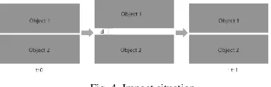
The physical situation to be analysed is that in which the object receives a load coming from a single impact. This impact is caused by a second object which displacement causes it to fall from a given distance, and which effect will be perceived through an internal energy flow in the first object. The single impact, as assumed by this study, is caused by a sudden agitation of the load, causing the object located immediately above to jump and fall on top of the object below, within a time span of 1 second. This event is described in Figure 4.
Fig. 4. Impact situation
The simulation is based upon the implementation of the Finite Element Method [36], following the mathematical approach described in Section II-D. The purpose is to determine, through the decomposition of the surface in minor elements, the displacements that occur in the object when receiving an impact.
impact occurs is most likely the result of a chain reaction provoked by a sequence of impacts created, for instance, by an improper handling during the stacking process. Furthermore, the effects of said impact are reflected in the entire volume of the object, which means that the event takes place in a three-dimensional environment, increasing the complexity of the calculations required to analyse the situation. Additionally, external factors such as the packaging methods and conditions can also have an incidence in the way the object behaves throughout a typical handling procedure.
Therefore, for purposes of the study, the initial problem has been simplified to its most basic expression, which consists on the evaluation of the behaviour object in its cross section, under the effects of a single impact derived from a random displacement during the transportation or handling stage.
2) Boundary conditions: As a starting point to approach the present case study, the cross section of the compressed element is taken, in order to transform the event into a two-dimensional problem.
The following are the boundary conditions set for said analysis:
• The object is restricted in its bottom surface.
• The diverse transportation and handling scenarios give place to multiple possibilities of displacement in the first instant of the analysis. For this particular study, two cases are defined, as seen in Figure 5:
◦ The object receives an impact at the centre of the cross section.
◦ The object is hit at the top border.
Fig. 5. Simulation scenarios
The setup of these initial conditions pretends to simulate the experimental situation under which the stacking and manipulation scenario has been modelled, generating in consequence a set of data that will serve as a reference element for the validation of the results of this analysis.
3) Algorithm description: For the implementation of the posed problem, the simulation aims to model the mechanics of waves propagating and attenuating through the nodes in the domain extracted from the cross section on the sample of compressed hygroscopic material. For this purpose, the setup of the algorithm is formulated under the scalar wave equation
modelling acoustic wave propagation as expressed in 1. Acknowledging that the distribution and subdivision of elements correspond to the particles of the compressed material which behave according to the established boundary conditions selected for the material under testing, and can hereby be decimated and configured in distribution according to material configuration requirements, a workflow of code has been implemented.
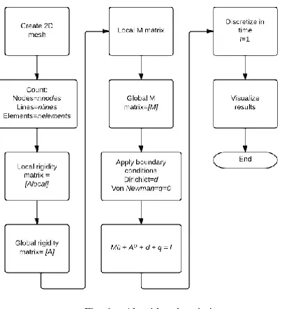
The algorithm, as described in Figure 6 begins with the creation of a two-dimensional mesh subdivided into triangular elements; the mesh represents the cross section of the geometry to be analysed. This step is followed by the implementation of a routine that allows the identification of the number of nodes, lines and elements that configure the mesh. The computation of this data enables the calculation of the local rigidity matrices of each of the elements that compose the mesh. The resulting matrices will be later assembled into a global rigidity matrix. This procedure is followed by the calculation of the local M matrices, which are also assembled altogether into a global matrix. Afterwards the process continues with the calculation of the remaining elements of the equation (l, d).
The boundary conditions of the problem are then processed and the result is operated into the previously established discrete equation. Finally, a discretization in time is operated within a given interval that makes sense for the problem under evaluation.
Fig. 6. Algorithm description
What the simulation displays is basically the propagation of loads throughout the entire surface, creating displacements in the nodes adjacent to that in which the force is applied, in this case, ; this propagation will happen in the shape of a wave, after the single impact creates an initial displacement in the first node, . A description of this situation under the particular scenario of an impact in the top border of the cross section is depicted in Figure 7.
Fig. 7. Nodal activity: F 1 applied to ni
This displacement will create an oscillation of the nodes, meaning that every node under the effect of the wave propagation will displace and then take an amount of time to return to its original position. This time is transformed into a frequency applying the formula . An example of the displacement of a t particular node and its associated frequency can be seen in Figure 8.
In this case, taking into account that for the case under study the impact is a single-occurrence event, the time interval is 1 second; the effects of such impact –namely the oscillation of the node– can be perceived in the initial fraction of the time frame, and afterwards the nodes come to rest.
Fig. 8. Analysis of the oscillation of node ni in time
5) Simulation results analysis: The graphic result of the simulation is seen in Figure 9, which reflects the behaviour of the object when hit at the centre of its cross section (a), and at the top border (b).
What is depicted in the visualization in Figure 9, is the wave propagation, under an analysis procedure carried out in the specific time interval of 1 second. The results show that, under the action of an exerted force that represents an approximate frequency of 50Hz, the object suffers significant deformations. The visualization depicts the internal displacements produced in the object, which will eventually cause severe damage to the overall structure and generate cracking and/or crumbling.
Fig. 9. Cross section analysis: (a) Impact in the centre of the cross section, (b) Impact in the top border
B. Vibration analysis: Experimentation
The second analysis aims to evaluate vibration effects on the compressed powder, which are particularly likely to take place during transportation stages.
In this case, the target scenario is a load truck travelling at a speed between 30 and 60 km/h, in which the object is being transported. This situation in general provokes a spectrum of vibration frequencies through which a set of loads is induced to the product [13]. The identification and prevention of such loads is precisely the focus of this study.
1) Experiment setup: In order to physically simulate the set out situation, a testing device has been designed. This device, when mounted over a controlled vibrating platform, replicates the problem to be analysed by creating multiple vibrations that can eventually generate a permanent impact in the product being studied.
Particularly, it aims to reproduce the transportation scenario, involving vibration produced by diverse sources, such as road conditions, suspension or the vehicle engine itself.
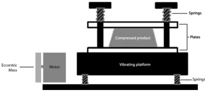
The device is composed of two plaques that exert regulated pressure to the surfaces of the product, while conducting externally induced vibrations, generated by a vibrating platform, which, in this case, simulates the oscillations suffered by the product during transport. Figure 10 shows a schematic diagram of the testing device.
The springs on top of the compressed product have a constant of 4.9N/mm, and the preload of 10N applied to them represents a distributed mass of 3Kg on top of the object. This simulates a situation where the product has a stack of 12 objects on top of it. On the other hand, the springs that support the vibrating platform have a constant of 30N/mm.
Fig. 10. Testing device diagram
The assembly shown in Figures 10 and 11, equipped with precision drives that control the oscillation frequency and accelerometers, enables the overall system to create a vibration pattern thanks to the mounting on the springs and the force exerted by the eccentric mass. This conducts to the acquisition of relevant data regarding the behaviour of both the device and the product, such as resonance frequencies and the overall performance of the product under given vibration conditions.
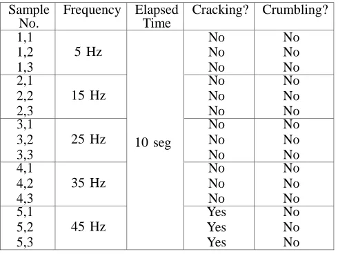
2) Experiment results: The results of the execution of the testing procedure are shown in Table I.
The purpose of the frequency variation is to cover a wide
spectrum of transportation conditions, given that the vibrating patterns may vary highly depending on the transportation means.
Illustrations shown in Figure 12 are the results obtained in the physical samples after the testing procedure. Particularly, the validation with the testing device showed that samples started presenting signs of failure from a frequency of 45Hz onwards.
Fig. 11. Testing device prototype
Fig. 12. Vibration effects on the product: (a) Crumbling; (b) Cracking
The testing procedure established that an in-depth analysis of the behaviour of the product is clearly required, given that trucks can reach vibrations close to a frequency of 60 Hz [37]. This means that, if the packaged stacks experience a vibration condition similar to the one simulated in the test, fracture and damage are to be expected.
In this sense, a more detailed understanding of the effects of vibration or impact on the product will help devise a solution for the prevention of damage during transport.
V. CONCLUSIONS AND FUTURE WORK
The most relevant result of the study is the development of the calculation tool, in which it will be possible to replicate a series of scenarios that simulate diverse conditions of the lifecycle of the product in a non-destructive fashion.
In order to gain accuracy in the simulated environment, it is necessary to fully characterize the material, particularly in aspects such as:
• Wave propagation speed in the evaluated materials, when compacted at different pressures. This can be achieved through the execution of an ultrasound test.
• Density associated with compaction pressure of the material and related volume data.
Having set this caveat, it can be assured that the implementation of the Finite Analysis Method (FEA) for the study of the behaviour of a wave through a specific medium, supported in experimental tests, complements the analysis of the results, and aids in the validation of the obtained data for future studies. The applicability of the virtual calculation environment and the experimental setup seems evident for future tests, which will simulate different life- cycle scenarios of the product without the need of exhaustively destroying product samples. It is important to note, however, that the two- dimensional conditioning of the virtual study doesn’t fully reflect the boundary conditions that delimit the real problem, taking into account that it is effectively a three-dimensional situation, and therefore, the result is not a completely accurate reflection of the conditions of the actual environment.
Table I Test Results
This data, complemented with the experimental observations performed on the product, show that the compression pressure of 20KN accomplishes the agglomeration requirements of the product handling and packaging, but it is also clear that the product itself might eventually suffer damage if certain conditions cause it to reach frequencies close to 50Hz. Therefore, the task that follows this analysis will be, clearly, the proper definition of the design characteristics for the packaging structure to be employed.
In particular, attention must be driven to the development of cushioning mechanisms that prevent products from displacing or sliding inside the packaging itself, and will consequently eliminate the likelihood of occurrence of the impact and vibration scenarios presented in this research
ACKNOWLEDGMENTS
The authors would like to thank the Research De- partment of EAFIT for their valuable support during the
execution of the research. The authors would also like to thank the collaborators at the Mechatronics Laboratory for their cooperation during the experimentation stages of the research. Finally, the authors would like to give a special mention to Prof. Manuel Julio Garc´ıa for his support during the formulation of the mathematical models behind the simulation process that came as a result of this project.
REFERENCES
[1] V. Rouillard and R. Richmond, “A novel approach to analysing and simulating railcar shock and vibrations,” Packaging Technology and Science, vol. 20, no. 1, pp. 17–26, 2007. [2] M. A. Sek and V. Rouillard, “Behaviour of multi-layered
corrugated paperboard cushioning systems under impact loads,” Applied Mechanics and Materials, vol. 3, pp. 383–390, 2005. [3] D. Hellström and F. Nilsson, “Logistics-driven packaging
innovation: a case study at ikea,” International Journal of Retail & Distribution Management, vol. 39, no. 9, pp. 638–657, 2011. [4] A. Lockamy III, “A conceptual framework for assessing strategic
packaging decisions,” International Journal of Lo- gistics Management, The, vol. 6, no. 1, pp. 51–60, 1995.
[5] F. Chan, H. Chan, and K. Choy, “A systematic approach to manufacturing packaging logistics,” The International Journal of Advanced Manufacturing Technology, vol. 29, no. 9-10, pp. 1088–1101, 2006.
[6] Z. Wang, C. Wu, and D. Xi, “Damage boundary of a pack- aging system under rectangular pulse excitation,” Packaging Technology and Science, vol. 11, no. 4, pp. 189–202, 1998.
[7] M. E. G. Quintana and R. E. Paull, “Mechanical injury during postharvest handling ofsolo’papaya fruit,” Journal of the American Society for Horticultural Science, vol. 118, no. 5, pp. 618–622, 1993.
[8] D. Martinez-Romero, M. Serrano, A. Carbonell, S. Castillo, F. Riquelme, and D. Valero, “Mechanical damage during fruit post-harvest handling: technical and physiological im- plications,” in Production practices and quality assessment of food crops. Springer, 2004, pp. 233–252.
[9] J. Subero and M. Ghadiri, “Breakage patterns of agglom- erates,” Powder Technology, vol. 120, no. 3, pp. 232–243,2001. [10] R. Moreno-Atanasio and M. Ghadiri, “Mechanistic analysis and
computer simulation of impact breakage of agglom- erates: effect of surface energy,” Chemical engineering science, vol. 61, no. 8, pp. 2476–2481, 2006.
[11] J. Foley, “Transportation shock and vibration descriptions for package designers.” Sandia Labs., Albuquerque, N. Mex., Tech. Rep., 1972.
[12] G. O. Rissi, S. P. Singh, G. Burgess, and J. Singh, “Measure- ment and analysis of truck transport environment in brazil,” Packaging Technology and Science, vol. 21, no. 4, pp. 231–246, 2008. [13] V. Chonhenchob, S. Sittipod, D. Swasdee, P. Rachtanapun, S.
Singh, and J. A. Singh, “Effect of truck vibration during transport on damage to fresh produce shipments in thailand,” Industrial Technology, p. 6, 2009.
[14] F. Lu, Y. Ishikawa, T. Shiina, and T. Satake, “Analysis of shock and vibration in truck transport in japan,” Packaging Technology and Science, vol. 21, no. 8, pp. 479–489, 2008. [15] S. P. Singh, A. Sandhu, J. Singh, and E. Joneson, “Measure- ment
and analysis of truck and rail shipping environment in india,” Packaging Technology and Science, vol. 20, no. 6, pp. 381– 392, 2007.
[16] M.-A. Garcia-Romeu-Martinez, S. P. Singh, and V.-A. Cloquell-Ballester, “Measurement and analysis of vibration levels for truck transport in spain as a function of payload, suspension and speed,” Packaging Technology and Science, vol. 21, no. 8, pp. 439–451, 2008.
[17] V. Rouillard, “Generating road vibration test schedules from pavement profiles for packaging optimization,” Packaging technology and Science, vol. 21, no. 8, pp. 501–514, 2008. [18] C. Bernad, A. Laspalas, D. Gonza´lez, E. Liarte, and M. A.
Jime´nez, “Dynamic study of stacked packaging units by operational modal analysis,” Packaging Technology and Science, Sample
No.
Frequency Elapsed Time
Cracking? Crumbling?
1,1 1,2 1,3
5 Hz
10 seg
No No No No No No 2,1 2,2 2,3
15 Hz
No No No No No No 3,1 3,2 3,3
25 Hz
No No No No No No 4,1 4,2 4,3
35 Hz
No No No No No No 5,1 5,2 5,3
45 Hz
vol. 23, no. 3, pp. 121–133, 2010.
[19] F. Lu, Y. Ishikawa, H. Kitazawa, and T. Satake, “Effect of vehicle speed on shock and vibration levels in truck transport,” Packaging Technology and Science, vol. 23, no. 2, pp. 101– 109, 2010.
[20] B. Jarimopas, S. Toomsaengtong, S. P. Singh, J. Singh, and R. Sothornvit, “Development of wholesale packaging to prevent post-harvest damage to rose apples,” Industrial Technology, p. 38, 2007.
[21] T. Acıcan, K. Alibas¸, and I. O¨ zelko¨ k, “Mechanical damage to apples during transport in wooden crates,” Biosystems engineering, vol. 96, no. 2, pp. 239–248, 2007.
[22] M. A. Al-Shammari and M. Al-Waily, “Theoretical and numerical vibration investigation study of orthotropic hyper composite plate structure.”
[23] M. E. Moreno, V. Tita, and F. D. Marques, “Finite element analysis applied to evaluation of effective material coeffi- cients for piezoelectric fiber composites,” in 2009 Brazilian Symposium on Aerospace Eng. & Applications, 2009.
[24] Y. Mohammed, M. K. Hassan, and A. Hashem, “Finite element computational approach of fracture toughness in composite compact-tension specimen,” International Jour- nal of Mechanical and Mechatronics Engineering, IJMME- IJENS, vol. 12, no. 04, 2010.
[25] T. H. Almusallam, H. Elsanadedy, H. Abbas, T. Ngo, and P. Mendis, “Numerical analysis for progressive collapse po- tential of a typical framed concrete building,” International Journal of Civil & Environmental Engineer, vol. 10, no. 2, pp. 40–46, 2010. [26] S. Y. Qassab, H. A. Sultan, and S. O. Mohammad, “Modal
analysis of pneumatic two finger robotic hand by finite element analysis and experimental testing.”
[27] J. T. Nelson and H. J. Saurenman, “A prediction procedure for rail transportation groundborne noise and vibration,” Transportation Research Record, vol. 1143, pp. 26–35, 1987. [28] D. Chua, C. Koh, and K. Lo, “Performance of urban rail transit
system: vibration and noise study,” Journal of performance of constructed facilities, vol. 11, no. 2, pp. 67– 75, 1997.
[29] M. Van Zeebroeck, H. Ramon, J. De Baerdemaeker, B. Nicola¨ı, E. Tijskens et al., “Impact damage of apples during transport and handling,” Postharvest biology and technology, vol. 45, no. 2, pp. 157–167, 2007.
[30] M. Van Zeebroeck, E. Tijskens, E. Dintwa, J. Kafashan, J. Loodts, J. De Baerdemaeker, and H. Ramon, “The discrete element method (dem) to simulate fruit impact damage during transport and handling: Case study of vibration damage during apple bulk transport,” Postharvest biology and technology, vol. 41, no. 1, pp. 92–100, 2006.
[31] S. Harada, S. Takagi, and Y. Matsumoto, “Wave propagation in a dynamic system of soft granular materials,” Physical Review E, vol. 67, no. 6, p. 061305, 2003.
[32] G. Gong and X. Zha, “Dem simulation of undrained behaviour with preshearing history for saturated granular media,” Modelling and Simulation in Materials Science and Engineering, vol. 21, no. 2, p. 025001, 2013.
[33] Z. Ning, R. Boerefijn, M. Ghadiri, and C. Thornton, “Dis- tinct element simulation of impact breakage of lactose agglomerates,” Advanced Powder Technology, vol. 8, no. 1, pp. 15–37, 1997. [34] A. Raji and J. Favier, “Model for the deformation in agricul- tural
and food particulate materials under bulk compressive loading using discrete element method. i: Theory, model development and validation,” Journal of food engineering, vol. 64, no. 3, pp. 359– 371, 2004.
[35] L. Beilina, “The finite element method for the wave equation,” http://www.math.chalmers.se/ larisa/www/FEMWaveEq.pdf, 2011.
[36] M. Garcia, Lecture Notes on Numerical Analysis. Medellin: Fondo Editorial Universidad EAFIT, 2008.
[37] V. Chonhenchob, S. P. Singh, J. J. Singh, S. Sittipod, D. Swasdee, and S. Pratheepthinthong, “Measurement and analysis of truck and rail vibration levels in thailand,” Packaging