Highly Accurate and Fully Automatic 3–D Head Pose
Estimation and Eye Gaze Estimation Using RGB-–D
Sensors and 3D Morphable Models
Reza Shoja Ghiass1,† and Denis Laurendeau2,†
1 Affiliation 1; [email protected]
2 Affiliation 2; [email protected]
* Correspondence: [email protected]; Tel.: +1-(418) 656-2131, ext. 2979 † Current address: 1665 Rue de l’Universite, Universite Laval, Quebec, QC, Canada, G1V 0A6
Version October 15, 2018 submitted to Sensors
Abstract:This work addresses the problem of automatic head pose estimation and its application in 1
3D gaze estimation using low quality RGB–D sensors without any subject cooperation or manual 2
intervention. The previous works on 3D head pose estimation using RGB–D sensors require either 3
an offline step for supervised learning or 3D head model construction which may require manual 4
intervention or subject cooperation for complete head model reconstruction. In this paper, we 5
propose a 3D pose estimator based on low quality depth data, which is not limited by any of the 6
aforementioned steps. Instead, the proposed technique relies on modeling the subject’s face in 3–D 7
rather than the complete head, which in turn, relaxes all of the constraints with the previous works. 8
The proposed method is robust, highly accurate and fully automatic. Moreover, it does not need any 9
offline step. Unlike some of the previous works, the method only uses depth data for pose estimation. 10
The experimental results on the Biwi head pose database confirm the efficiency of our algorithm 11
in handling large pose variations and partial occlusion. We also evaluate the performance of our 12
algorithm on IDIAP database for 3D head pose and eye gaze estimation. 13
Keywords:3–D Morphable Models; 3–D Head Pose Estimation; 3–D Eye Gaze Estimation; Iterative 14
Closest Point; RGB–D Sensors; 15
1. Introduction 16
Head pose estimation is a key step in understanding human behavior and can have different 17
interpretations depending on the context. From the computer vision point of view, head pose estimation 18
is the task of inferring the direction of head from digital images or range data compared to the imaging 19
sensor coordinate system. In the literature, the head is assumed to be a rigid object with three degrees 20
of freedom, i.e., the head pose estimation is expressed in terms of yaw, roll and pitch. Generally, the 21
previous works on head pose estimation can be divided into two categories: (i) the methods based 22
on 2D images, and (ii) depth data [1]. The pose estimators based on 2D images generally require 23
some pre–processing steps to translate the pixel–based representation of the head into some direction 24
cues. Several challenges such as camera distortion, projective geometry, lighting, changes in facial 25
expression exist in 2D image–based head pose estimators. A comprehensive study of pose estimation 26
is given in [1] and the reader can refer to this reference for more details on the literature. 27
Unlike the 2D pose estimators, the systems based on 3D range data or their combination with 2D 28
images have demonstrated very good performance in the literature [2–7]). While most of the work on 29
3D pose estimation in the literature is based on non–consumer level sensors [8–10], recent advances 30
in production of consumer level RGB–D sensors such as the Microsoft Kinect or the Asus Xtion has 31
Submitted toSensors, pages 1 – 14 www.mdpi.com/journal/sensors
facilitated the design and implementation of real-time facial performance capture systems such as 32
consumer-level 3D pose estimators, 3D face tracking systems, 3D facial expression capture systems 33
and 3D eye gaze estimators. In this paper, we focus on the recent 3D pose estimators and tracking 34
systems based on consumer level RGB–D sensors. 35
According to the literature [11], 3D head pose estimation is a key part of 3D eye gaze estimation. 36
In other words, head pose estimation problem is highly correlated with the problem of gaze estimation. 37
In this paper, we propose the design of reliable head pose estimation systems first and integrate it in a 38
state of the art gaze estimation system next. 39
1.1. Related Work on 3D Pose Estimation using RGB–D sensors 40
The 3D head pose estimation systems can be divided into three categories: (i) statistical approaches, 41
(ii) model based posed estimation methods, and (iii) facial feature based pose estimation techniques 42
[12]. Each of these approaches comes with their specific limits and advantages. Statistical methods 43
may need a large database for training a regressor. However, they can estimate the subject head pose 44
on air, i.e., the system can estimate the head pose for each frame even in a shuffled video sequence. 45
In contrast, model based approaches generally need an offline step for subject–specific head model 46
reconstruction with significant subject cooperation. Next, a point cloud registration technique such 47
as rigid/non–rigid ICP should be used to register the model with depth data. In other words, unlike 48
the supervised learning based approaches, they are generally based on tracking. So, re–initialization 49
becomes a challenge. Facial feature based pose estimation techniques try to track facial features or 50
patches, which in turn, can help in calculation of pose using techniques such as PnP [13] or encoding 51
the face 3D shape using view-invariant descriptors and infer head pose through matching [14]. 52
To the best of our knowledge, one of the most important works on pose estimation using 53
consumer level RGB–D sensorsis the work of Fanelli et al. [2,3]. As the authors provide a ground 54
truth data and a database for comparison, their work has become the gold standard for comparison in 55
the literature. They work falls in the category of statistical approaches. In their work, the authors 56
proposed a pose estimation system based on Random Forests. For the evaluation of their system, 57
they acquired a database of 20 subjects which is called the Biwi head pose database. Next, they 58
divided the database into a training and test set. Afterward, a commercial face tracker was used 59
for annotation of the training set, i.e., a subject specific head model was constructed using the 60
commercial system to match each person’s identity and track the head in training depth frames. The 61
commercial tracker measured a subject’s 3D head locations and orientations, which in turn, were 62
used to train their regression based system. Finally, some patches of fixed size from the region of the 63
image containing the head as positives samples, and from outside the head region as negatives were 64
randomly selected for training the system. A major limitation of this system was that it required 65
an offline training phase with subject cooperation. Moreover, the performance of the system in the 66
testing phase was subject to the output of the commercial head tracker in the training phase. In 67
[3] the authors continued their previous work [2] by creating a dataset of synthetic depth images 68
of heads, and extracting the positive patches from the synthetic data, while using the original 69
depth data to to extract negative patches. A drawback of this system was the limited number of 70
synthetic models and negative patches for performing a regression task, without learning subject’s 71
own head [3]. [15] proposed a system based on cascaded tree classifiers with higher accuracies 72
than Fanelli et al. [9] proposed a 3D face tracker based on particle filters. The main idea in their 73
system was the combination of depth and 2–D image data in the observation model of the particle filter. 74
75
With the main intention of designing a gaze estimator, Funes and Odobez [7,16] proposed the first 76
model based pose estimator by building a subject–specific model based face tracker using Iterative 77
Closest Point (ICP) and 3D Morphable Models. Their system was not only able to estimate the pose, but 78
was also able to track the face and stabilize it. A major limitation of their method was the offline step 79
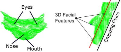
Figure 1.Depth data obtained from the first frame and visualized from profile. It consists of both facial part and spurious data.
(eye corners, eyebrows, mouth corners) on RGB image of the subject, and consequently added an 81
extra term to the cost function in their ICP formulation. In other words, their ICP formulation was 82
supported by a manual term. Moreover, the user had to cooperate with the system and turn the head 83
from left to right. Recently, the authors have proposed a more recent version of their system in the 84
work of [12] without the need for manual intervention. 85
1.2. Contribution of the proposed 86
Unlike [2,3,7,16] our proposed system does not require any commercial system to learn a subject’s 87
head nor any offline step. A key contribution of our approach is proposing a method to automatically 88
learn a subject’s 3D face rather than the entire 3D head. As a consequence, we no longer need subject’s 89
cooperation (i.e., turning the head from left to right) which is important in previous works for model 90
based pose estimation systems. In addition, unlike [7] our system does not require any manual 91
intervention for model reconstruction. Instead, we rely on Haar features and boosting for facial feature 92
detection, which in turn, can be used for face model construction. Note that we use only one RGB 93
frame for model reconstruction. The tracking step is based on depth frames only. After learning a 94
subject’s face, the pose estimation task is performed by a fully automatic, user non–cooperative and 95
generic ICP formulation without any manual term. Our ICP formulation is robustified with Tukey 96
functions in tracking mode. Thanks to the Tukey functions, our method successfully tracks a subject 97
face in challenging scenarios. The outline of the paper is as follows: The method details are explained 98
in section 2. Afterward, the experimental results are discussed in section 3. Finally, the conclusions are 99
drawn in section 4. 100
2. Method Details 101
Our method consists of four key steps:(i) Geometry processing of a generic face model and the 102
first depth frame, (ii) generic face model initialization (i.e., model positioning at the location of the 103
head), (iii) subject–specific face model construction by morphing the initialized generic model, and 104
(iv) tracking the face in the next depth frames using the subject–specific face model. In our proposed 105
system, we only model the face of the subject rather than the entire head, which in turn, helps us to 106
design a very robust, accurate and non–cooperative head tracking and pose estimation system. To 107
accomplish this goal, a generic model is positioned on the subject’s face in depth data. Next, it learns 108
the subject’s face and finally starts to track it. Bothpositioninga generic model on subject’s face and 109
trackingit in depth data are accomplished using an ICP based technique. However, the ICP registration 110
technique which serves for positioning faces a major challenge: the generic model is a model of a 111
complete head and not only the face. On the other hand, the depth data contains not only the face of 112
the subject as well as the other parts such as the torso or the background (Fig.1). Note that a major 113
difficulty with ICP is its sensitivity to outliers and missing data between two 3D point clouds. To tackle 114
this problem in model initialization, we perform geometry processing which is explained next. 115
2.1. Geometry processing 116
In this step, the goal is trimming the depth data and the generic model in order to remove spurious 117
Figure 2.Face and facial features detection from the first RGB frame of a subject
Eyes
Nose
Mouth
3D Facial Features
Cropping Pla ne
Figure 3.Trimming the first depth frame: (left) upper view, (right) profile view
should initialize (position) the model at the position of the subject’s head, before tracking starts. For 119
this purpose, we capture the entire environment using the Kinect. Next, we filter out the spurious 120
point cloud and just keep the region of interest in the first depth frame, i.e., the facial surface. For this 121
purpose, the first depth frame is automatically trimmed in order to discard the residual data. To this 122
end, we need to automatically detect and localize the facial features (i.e., eyes, nose, and mouth) on 123
the point cloud in order to determine the way the depth data should be trimmed. Detection of the 124
facial features from a noisy depth frame directly is a challenge. Fortunately, the Kinect provide us the 125
first RGB frame. So, the face and facial features are detected on the first RGB frame by first using Haar 126
features and boosting ([17]). Fig.2demonstrates an example of the face and facial feature detection. 127
As some false detections may occur, the next step is to reject them automatically. This is accomplished 128
by utilizing the prior knowledge about the structure of a face and the relative positions of eyes, nose 129
and mouth on a detected face. 130
After the features are detected on the first RGB frame, their 3Dloci are determined on the first 131
depth frame through back projection using Kinect calibration data. In order to trim the depth data, a 132
3D plane passing through the 3D coordinates of the eyes and mouth is defined and shifted by an offset 133
equal to the distance between the left and right eye. The shifted plane is calledthe cropping plane. Next, 134
the depth data beneath the plane is discarded. Fig.3shows the 3D loci of the facial features on the 135
corresponding depth data trimmed by the cropping plane. 136
Once the subject’s face is captured and trimmed in 3D, the next step is to construct a model which 137
simulates the subjects face (rather than the complete head). The type of 3D model we use to simulate 138
the subject’s identity is a family of Active Appearance Models (AAMs) called 3D Morphable models. 139
Using these models, a subject’s 3D head scan can be reconstructed by adding a set of weighted principal 140
components (PCs) to the mean shape (the mean shape is the mean of all of the 200 subject’s face scans 141
in the database). For instance, we focus on the mean shape of the model. Much like trimming the 142
depth data, the mean shape of the 3D Morphable model is trimmed in order to facilitate the procedure 143
of subject specific model construction through registration. In this context, a plane similar to that of 144
Fig.3(b) is fitted to the model’s mean shape. Once the mean shape is trimmed, it should be scaled to 145
the size of the subject’s face in 3D space. To this end, the model is scaled so the distance between the 146
left and right eyes of the model and that of the subject’s face scan (i.e., the first depth frame) becomes 147
Figure 4.Trimming the 3D Morphable model mean shape: (left) before trimming, and (right) after trimming
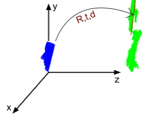
R,t,d
y
x
z
Figure 5.Positioning the model on the face. The blue is the trimmed model, while the green is the subject scanned by the Kinect.
2.2. Generic Model Positioning 149
After processing both model and depth data, the trimmed model is positioned on the face of 150
the subject using rigid ICP. Fig.5demonstrates this step for the model and first depth frame. After 151
initializing the generic model on the subject’s face, the model is ready to morph and learn the subject’s 152
face (Sec.2.3) and track it afterward(Sec.2.4). 153
2.3. Learning and Modeling the Subject’s Face 154
Capturing the subject’s facial shape variations via morphing the mean shape is the main objective 155
of this step. This problem can be considered as finding the weights of shape PCs in the 3D Morphable 156
model, where each weight describes the contribution of its corresponding PC in simulating a subject’s 157
face. Much like the generic ICP problem, this part also can be described by minimization of a cost 158
function. So, we can unify both ICP and PCA terms into a unique equation and reformulate a more 159
generic ICP problem through minimizing the following energy function ([18]): 160
E(Z,d,R,t) =ω1Ematch+ω2Erigid+ +ω3Emodel
Ematch = n
∑
i=1(NTi (zi−CY(zi)))2
Erigid= n
∑
i=1kzi−(Rxi+t)k22
Emodel = n
∑
i=1kzi−(Pid+mi)k22
(1)
whereYis the target surface inR3,Xis the source surface, andZis a deformed version ofX 161
which should be aligned withY. Notice also thatCy(zi)is the closest point in the target surface to the 162
pointzi(i=1, 2, ...,n, wherenis the number of points in source). In this equation, the first term is the 163
term is the model error (for more details about these error the reader is referred to [18]). The energy 165
function can be minimized by linearizing Eq.1and iteratively solving the following linear system: 166
argmin
Zt+1i ,d,Re,et
n
∑
i=1ω1(nTi (zit+1−CY(zi)t))2+
ω2kzti+1−(Re(Rxi+t) +et)k22+
ω3kzti+1−(Pid+mi)k22
(2)
wheretis the number of iterations,z0i =xi,dcontains the weights of PCs, and ˜R and ˜t are the 167
linear updates which we obtain for the rotation (R) and translation (t) matrices at each iteration. Notice 168
thatniis the normal to the surface at pointCY(zi)t, i.e., point to plane matching error. For more details, 169
the reader is referred to the tutorial by [18]. 170
2.4. 3D Head Tracking and Pose Estimation 171
Once the model is constructed from the first depth frame, the pose (orientation alone) of the 172
head can be calculated directly from the rotation matrix,R, in terms of roll, pitch and yaw [19]. In 173
Sec.2.3, the rotation matrix corresponding to the first depth frame of the subject was obtained during 174
model construction. A question arises here: How can one obtain the rotation matrices for the next 175
depth frames? Indeed, this question is addressed by 3D registration of the form of Eq.1with some 176
differences. The first difference is that we no longer need to capture the subject’s face variations,d, 177
because it is calculated once for the entire procedure. So, theEmodel term is dropped from Eq.1. The 178
other difference is that we no longer need to trim the next depth frames. The reason is that the model is 179
already fitted to the first depth frame during model construction (see Fig.5) and we expect the system 180
to work in tracking mode. In tracking mode, head displacement in the next frame compared to the 181
current frame is small and the model displacement should be very small compared to the initialization 182
mode. So, instead of trimming the next depth frames, one can take advantage of registration using 183
Tukey functions, which will filter out bad correspondences with large distances. The pose estimation 184
procedure for the next depth frames is as follows: for the second depth frame, the model rotation and 185
translation increments are calculated relative to that of the first depth frame. Next, the rotation and 186
translation matrices for the second depth frame are obtained by applying the updates to the rotation 187
and translation matrices in the first depth frame. This procedure is continued for the next frames. For 188
each frame, the head pose can be directly calculated from the rotation matrix in terms of pitch, yaw 189
and roll. 190
Robustness of Registration to Outliers 191
As mentioned, partial overlap between source and target and outliers in the data are the most 192
challenging problems in registration through ICP [20]. Two types of outliers exist: (i) outliers in the 193
source point cloud and (ii) outliers in the target point cloud. Discarding unreliable correspondences 194
between the source and the target is the most common way to handle this problem. In Sec.2.2, this 195
goal was accomplished by trimming both model and depth data in the first depth frame. However, 196
for the 3D face tracking mode the same method can not be used. The reason is that the initialization 197
modality is based on detection of facial features. Applying facial feature detection for each frame 198
can decrease the frame rate at which the system operates. On the other hand, a limit of our method 199
is that the system can not start from an extreme pose, as the facial feature detection algorithms will 200
fail. Fortunately, as the model is already positioned onto the face of the subject, we no longer need 201
to trim the upcoming depth frames to perform tracking using ICP. Instead, we use Tukey functions 202
to robustify the ICP. Tukey functions assign less weight to the bad correspondences and decrease or 203
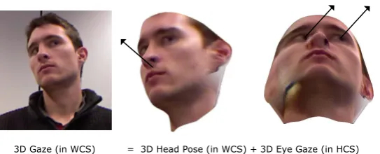
3D Gaze (in WCS) = 3D Head Pose (in WCS) + 3D Eye Gaze (in HCS) =
Figure 6.Applying the face texture in (a) to the subject specific model. The subject is chosen from IDIAP database. The figure in (b) is the pose free model visualized from down side of the subject, the figure in (c) is the same pose free model visualized from right side, the figure in (d) is the same pose free model visualized from left side, while the figure in (e) is the TPFM visualized from frontal view
Robustness of Registration to extreme pose 205
A question may arise at this point: Can the method handle the case of a face with extreme pose 206
where most facial parts cannot be sensed by the Kinect? In this case the model should be registered 207
with a partial point cloud of subject’s face. This leads to increasing the number of points in the source 208
(trimmed model) without good correspondences in the target (partial point cloud of face). As a result, 209
such points will form bad correspondences with relatively large Euclidean distance. Fortunately, 210
we also address this problem by using robust functions in the tracking mode, as robust functions 211
discard/decrease the effect of such bad correspondences in the energy function. To clarify this, notice 212
that bad correspondences inherently produce large Euclidean distances, while this is not the case 213
for good correspondences. On other other hand, narrow robust functions act as low pass filters and 214
discard the bad correspondences. 215
Robustness of Registration to Facial Expression Changes 216
As we use rigid ICP, facial expression changes may be considered as a challenging factor. In this 217
context, Funes and Odobez [7] used a mask and only consider the upper part of the face in the rigid 218
registration part of their system. Notice that we do not use such a mask. The reason is that, most of the 219
time, the subject may not showsignificantfacial expression changes (such as laughing or opening the 220
mouth). On the other hand, relying on more data of the face may result in a more robust registration 221
task. The problem becomes more challenging if we consider that self–occlusion may occur on the 222
upper part of the face. Due to this reasons, we prefer not to use a mask. Instead, we rely on the robust 223
Tukey functions to improve the robustness in the case of facial expression changes. 224
2.5. Gaze Estimation 225
In this paper, we will study the impact of the proposed 3D head pose estimator on the 226
appearance–based 3D gaze estimation systems of [16]. Inspired by a series of works in the literature, 227
we use the two supervised learning methods to calculate the gaze direction on the head coordinate 228
system (we will refer to this vector as the Gaze-on-Head vector or GoH in the remainder of this paper): 229
(i) A K–NN based approach and (ii) Adaptive Linear Regression (ALR) [7,16,21]. 230
231
2.5.1. Head Pose Stabilization 232
This step is a pre–processing step for gaze estimation. As soon as the head pose is calculated, the 233
texture of the corresponding RGB frame can be back–projected to a pose free 3D head model (Fig.5). 234
The 3D gaze vector is calculated on this pose free head model next, and the 3D head pose is added 235
back to the calculated 3D gaze vector to bring the 3D gaze vector back to the world coordinate system 236
(a) (b) (c) (d)
Figure 7.The mean [a] and the first [b], second [c] and third [d] principal components (visualized:±5 standard deviation) of the shape model. The images are taken from the database website
(a) (b) (c) (d)
Figure 8.The mean [a] and the first [b], second [c] and third [d] principal components (visualized:±5 standard deviation) of the texture model. The images are taken from the database website.
3. Experimental evaluation 238
In this section we report our empirical evaluation. We start by describing the data sets used in 239
our experiments, follow with an explanation of the evaluation protocol, and finish with a report of the 240
results and their discussion. 241
3.1. Databases 242
3.1.1. 3D Basel Face Model (BFM) 243
The 3D Basel Face Model (BFM) is a Morphable model calculated from registered 3D scans of 100 244
male and 100 female faces. The model geometry consists of 53,490 3D vertices connected by 160,470 245
triangles. The model is given by the followings: 246
• The mean shape 247
• 199 principal components (PCs) of shape obtained by applying PCA on 200 subjects facial shape 248
in the database 249
• The variance of shape 250
• The mesh topology 251
• The mean texture 252
• 199 principal components (PCs) of texture obtained by applying PCA on 200 subjects facial 253
texture in the database 254
• The texture variance 255
Figs.7 and 8 demonstrate the mean and the first, second and third principal components 256
(visualized:±5 standard deviation) of the shape and texture model respectively. 257
Any unknown face can be explained as a linear combination of the principal components and the 258
mean shape/texture. In this paper, we only use the shape data set (i.e, shape principal components 259
together with mean shape) for the construction of a subject’s specific face model (i.e, the head trackers). 260
3.1.2. Biwi Kinect Head Pose Database 261
We used the Biwi Kinect Head Pose Database ([2,3]) to evaluate the effectiveness of our method. 262
(a) a (b) b (c) c
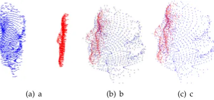
Figure 9. Registration procedure to capture subject’s variations, d, together with transformation matricesRandt: (a) before model initialization, (b) after model initialization and before capturing subject’s face variations, and (c) after the initialization is accomplished (ready for tracking).
for pose estimation reported in the literature. Secondly, it provides ground truth data for comparison, 264
and we wanted to make our results directly comparable to not only those of Fanelliet al.([2,3]), but 265
also to the recent works which have used this database. The dataset contains over 15000 depth frames 266
and RGB image of 20 people, six females and fourteen males, where four people were recorded twice. 267
The head pose ranges through about 75 degrees yaw and 60 degrees pitch. The ground truth for head 268
rotation is also provided by a commercial software. 269
3.1.3. EYEDIAP Database 270
We used EYEDIAP gaze database [22] to evaluate the effectiveness ofgaze estimationpart of 271
our method. There are several reasons for this choice. Firstly, to our best knowledge it is the only 272
Kinect based database for gaze estimation in the literature. Secondly, it provides ground truth data 273
for comparison of gaze estimation (bot not pose) results. In addition, we wanted to make our results 274
statistically comparable to the work of Funes and Odobez [7,16]. The dataset contains over 4450 depth 275
frames and RGB image of 16 people among them 14 subjects participated in a screen based gaze 276
estimation scenario. Each session itself is divided into two other session where the subject was asked 277
to keep the head stationary or moving. 278
3.2. Evaluation methodology 279
3.2.1. Subject Specific Model Construction 280
We evaluated the proposed algorithm in a setting in which the first RGB frame and the first depth 281
frame were used for learning in an unsupervised context, while the other depth frames were used for 282
testing. Fig.9demonstrates the registration procedure. In this figure, the blue point cloud is the (down 283
sampled) mean shape1of the BASEL data, while the red point cloud is the trimmed depth scan of the 284
first subject in the Biwi database (the subject in Fig.2). We want to register the two shapes with each 285
other and, at the same time, capture the variation of the subject’s face by minimizing Eq.1. 286
3.2.2. Pose Estimation and Tracking 287
After the subject’s specific model is constructed from the first (trimmed) depth frame, we drop 288
the model term from the energy function and continue the registration of the model and depth data. 289
The pose estimation for each frame can be directly calculated from the rotation matrix,R, obtained 290
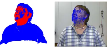
from registration. Fig.10(a) shows a sample where the model (red) is registered with the depth data 291
(blue). The model is superimposed on the corresponding RGB frame through the Kinect calibration 292
data in Fig.10(b) for a better visualization. 293
Figure 10. An instant of the tracking mode: the model (red) tracks the depth data (blue) and it is back–projected to the RGB frame
1000 2000 3000 4000 5000 6000 7000 8000 9000 10000
60
40
20 0 20 40 60
Pitch
ThemProposedmMethod GroundmTruth
1000 2000 3000 4000 5000 6000 7000 8000 9000 10000
60
40
20 0 20 40 60
Yaw
1000 2000 3000 4000 5000 6000 7000 8000 9000 10000
60
40
20 0 20 40 60
Frame
Roll
Figure 11.The experimental results of the proposed facial pose estimator on Biwi head pose database compared to the ground truth.
Fig.11shows the result of pose estimation in terms of yaw, depth, and roll for 10000 frames from 294
the Biwi head pose database compared to the ground truth. 295
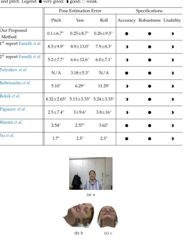
A summary of the key evaluation results and method features of the proposed algorithm compared 296
to two previous works is shown in Table 1. Four criteria were considered to compare the systems 297
according toPauly: 298
• Accuracy compared to the ground truth data 299
• Performance in terms of time and memory efficiency 300
• Robustness to occlusions, poor lighting and fast motion 301
• Usability in real scenarios, i.e., user–specific training, system calibration and manual intervention 302
need to be kept to a minimum. 303
On one hand our system demonstrates better results than [2,3] in terms of average error and 304
standard deviation. Both systems proposed by Fanelliet al.show slightly better performance than our 305
systemonlyin terms of standard deviation of roll. Moreover, our system is generic and the training 306
phase is performed with a single RGB/depth frame. On the other hand, the systems of Fanelliet 307
al.can work on a frame by frame basis, while our system can only work in tracking mode (i.e., the 308
subject’s head motion in successive frames should be small). Notice that both systems of Fanelliet al. 309
need a training phase supported by a commercial face tracker, while we propose a new face tracker in 310
this work. As both systems of Fanelliet al.require a training phase based on positive and negative 311
patches cropped from a database of 20 subjects, the generic aspect of their system is an issue. We also 312
compared our system to the other non–model based approaches of [9,13,15,24], and the results show 313
the effectiveness of the proposed system. The only comparable system is the model–based work of 314
[12] which shows very good precision too. 315
3.2.3. Face Stabilization and Gaze Estimation 316
Using the calibration matrices of the Kinect, it is possible to apply the texture from the RGB frames 317
to the constructed 3D model. [7,16] used this property for the first time to accomplish gaze estimation 318
the results with those of Funes and Odobez [7] for face pose estimation due to lack of details in yaw, roll and pitch. Legend: very good;H#good;#weak.
Pose Estimation Error Specifications
Pitch Yaw Roll Accuracy Robustness Usability
Our Proposed
0.1±6.7◦ 0.25±8.7◦ 0.26±9.3◦ H#
Method
1streportFanelliet al.
8.5±9.9◦ 8.9±13.0◦ 7.9±8.3◦ H# H#
2streportFanelliet al.
5.2±7.7◦ 6.6±12.6◦ 6.0±7.1◦ H# H#
Tulyakovet al.
N/A 3.18±5.3◦ N/A H#
Baltrusaitiset al.
5.10◦ 6.29◦ 11.29◦ H# H#
Rekiket al.
4.32±2.65◦ 5.13±3.33◦ 5.24±3.33◦ H# H#
Papazovet al.
2.5±7.4◦ 3±9.6◦ 3.8±16◦ H# H#
Martinet al.
2.54◦ 2.57◦ 3.62◦ H#
Yuet al.
1.7◦ 2.5◦ 2.3◦ H#
(a) a
(b) b (c) c
Figure 12.Applying the face texture from the RGB frame in (a) to the subject’s specific model. The figure in (b) is the model visualized from side view, while the figure in (c) is the same model visualized from down view
order to have a fully automatic gaze estimation system. Fig.12(a) shows the RGB frame of a subject, 320
while Figs.12(a) and (b) shows two different views of the same RGB frame warped to the subject’s 321
specific 3D model (in the facial area) using our proposed method. Note that the artifacts in perimeter 322
of the 3D head model is due to the cropping plane. 323
A summary of the key evaluation results and method features of the proposed algorithm compared 324
Table 2.A summary of the key evaluation results and method features of the proposed algorithm, and the previous work when Adaptive Linear Regression (ALR) is used and the subjects keep the head stationary: very good;H#good;#weak.
Gaze Estimation Error Specifications
Left Eye Right Eye Accuracy Robustness Usability
Our Proposed Method
7.55◦ 6.89◦ H#
Funes and Odobez Method
9.73◦ 10.5◦ H# H# H#
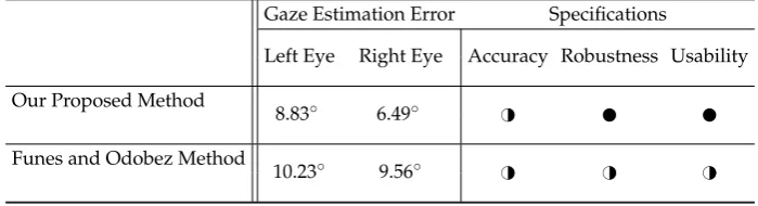
Table 3.A summary of the key evaluation results and method features of the proposed algorithm, and the previous work when K–NN is used and the subject keeps the head stationary: very good;H#
good;#weak.
Gaze Estimation Error Specifications
Left Eye Right Eye Accuracy Robustness Usability
Our Proposed Method
8.83◦ 6.49◦ H#
Funes and Odobez Method
10.23◦ 9.56◦ H# H# H#
Table 4.A summary of the key evaluation results and method features of the proposed algorithm, and the previous work when Adaptive Linear Regression (ALR) is used and the subjects have free head motion: very good;H#good;#weak.
Gaze Estimation Error Specifications
Left Eye Right Eye Accuracy Robustness Usability
Our Proposed Method
9.78◦ 9.49◦ H#
Funes and Odobez Method
15.57◦ 14.2◦ H# H# H#
• Accuracy compared to the ground truth data 326
• Robustness to occlusions, bad lighting and fast motions 327
• Usability in real scenarios, i.e., user–specific training, system calibration and manual intervention 328
need to be kept to a minimum. 329
Our system demonstrates better results than Funes and Odobez in terms of average gaze 330
estimation error. One possible reason for this can be the high precession of our pose estimation 331
system which performs almost like a commercial state of the art pose estimator, while the pose 332
estimator of Kenneth and Odobez shows slight deviation from our precise pose estimator, which result 333
#weak.
Gaze Estimation Error Specifications
Left Eye Right Eye Accuracy Robustness Usability
Our Proposed Method
9.03◦ 8.86◦ H#
Funes and Odobez Method
17.97◦ 14.63◦ H# H# H#
4. Conclusion 335
This work addressed the problem of automatic facial pose and gaze estimation without subject 336
cooperation or manual intervention using low quality depth data provided by the Microsoft Kinect. 337
The previous works on pose estimation using the Kinect were based on supervised learning or require 338
manual intervention. In this work, we proposed a 3D pose estimator based on low quality depth data. 339
The proposed method is generic and fully automatic. The experimental results on the Biwi head pose 340
database confirm the efficiency of our algorithm in handling large head pose variations and partial 341
occlusion. Our results also confirmed that model based approaches outperform the other approaches 342
in terms of precision. We also evaluated the performance of our algorithm on the IDIAP database for 343
3D head pose and eye gaze estimation and we obtained promising results. 344
5. Acknowledgement 345
The research presented in the paper was funded by grant F506-FSA of the Auto21 Networks of 346
Centers of Excellence Program of Canada. 347
348
1. Murphy-Chutorian, E.; Trivedi, M.M. Head pose estimation in computer vision: A survey. Pattern Analysis
349
and Machine Intelligence, IEEE Transactions on2009,31, 607–626. 350
2. Fanelli, G.; Weise, T.; Gall, J.; Van Gool, L. Real time head pose estimation from consumer depth cameras. In 351
Pattern Recognition; Springer, 2011; pp. 101–110. 352
3. Fanelli, G.; Dantone, M.; Gall, J.; Fossati, A.; Van Gool, L. Random Forests for Real Time 3D Face Analysis. 353
Int. J. Comput. Vision2013,101, 437–458. 354
4. Breitenstein, M.D.; Kuettel, D.; Weise, T.; Van Gool, L.; Pfister, H. Real-time face pose estimation from single 355
range images2008. pp. 1–8. 356
5. Fanelli, G.; Gall, J.; Van Gool, L. Real time head pose estimation with random regression forests2011. pp. 357
617–624. 358
6. Seemann, E.; Nickel, K.; Stiefelhagen, R. Head pose estimation using stereo vision for human-robot 359
interaction2004. pp. 626–631. 360
7. Funes Mora, K.A.; Odobez, J. Gaze estimation from multimodal Kinect data2012. pp. 25–30. 361
8. Morency, L.P. 3D Constrained Local Model for Rigid and Non-rigid Facial Tracking. Proceedings of the 2012 362
IEEE Conference on Computer Vision and Pattern Recognition (CVPR); IEEE Computer Society: Washington, 363
DC, USA, 2012; CVPR ’12, pp. 2610–2617. 364
9. Rekik, A.; Ben-Hamadou, A.; Mahdi, W. 3D Face Pose Tracking using Low Quality Depth Cameras. VISAPP 365
2013 - Proceedings of the International Conference on Computer Vision Theory and Applications, 2013, 366
10. Cai, Q.; Gallup, D.; Zhang, C.; Zhang, Z. 3D Deformable Face Tracking with a Commodity Depth Camera. 368
Proceedings of the 11th European Conference on Computer Vision Conference on Computer Vision: Part III; 369
Springer-Verlag: Berlin, Heidelberg, 2010; ECCV’10, pp. 229–242. 370
11. Hansen, D.; Ji, Q. In the Eye of the Beholder: A Survey of Models for Eyes and Gaze. Pattern Analysis and
371
Machine Intelligence, IEEE Transactions on2010,32, 478–500. 372
12. Yu, Y.; Mora, K.A.F.; Odobez, J.M. Robust and Accurate 3D Head Pose Estimation through 3DMM and 373
Online Head Model Reconstruction. 2017 12th IEEE International Conference on Automatic Face Gesture 374
Recognition (FG 2017), 2017, pp. 711–718. doi:10.1109/FG.2017.90. 375
13. Baltrusaitis, T.; Robinson, P.; Morency, L.P. 3D Constrained Local Model for rigid and non-rigid facial 376
tracking. 2012 IEEE Conference on Computer Vision and Pattern Recognition, 2012, pp. 2610–2617. 377
doi:10.1109/CVPR.2012.6247980. 378
14. Papazov, C.; Marks, T.K.; Jones, M. Real-time 3D head pose and facial landmark estimation from depth 379
images using triangular surface patch features. 2015 IEEE Conference on Computer Vision and Pattern 380
Recognition (CVPR), 2015, pp. 4722–4730. doi:10.1109/CVPR.2015.7299104. 381
15. Tulyakov, S.; Vieriu, R.L.; Semeniuta, S.; Sebe, N. Robust Real-Time Extreme Head Pose Estimation. 2014 382
22nd International Conference on Pattern Recognition, 2014, pp. 2263–2268. doi:10.1109/ICPR.2014.393. 383
16. Funes-Mora, K.A.; Odobez, J.M. Gaze estimation in the 3d space using rgb-d sensors.International Journal of
384
Computer Vision2016,118, 194–216. 385
17. Viola, P.; Jones, M. Rapid object detection using a boosted cascade of simple features2001. 1, I–511. 386
18. Bouaziz, S.; Pauly, M. Dynamic 2d/3d registration for the kinect2013. p. 21. 387
19. LaValle, S.M. Planning Algorithms; Cambridge University Press: Cambridge, U.K., 2006. Available at 388
http://planning.cs.uiuc.edu/node103.html. 389
20. Bouaziz, S.; Tagliasacchi, A.; Pauly, M. Sparse iterative closest point2013. 32, 113–123. 390
21. Lu, F.; Sugano, Y.; Okabe, T.; Sato, Y. Inferring human gaze from appearance via adaptive linear regression 391
2011. pp. 153–160. 392
22. Funes Mora, K.A.; Monay, F.; Odobez, J.M. EYEDIAP Database: Data Description and Gaze Tracking 393
Evaluation Benchmarks. Idiap-RR Idiap-RR-08-2014, Idiap, 2014. 394
23. Pauly, M. Realtime Performance-Based Facial Avatars for Immersive Gameplay2013. pp. 23:23–23:28. 395
doi:10.1145/2522628.2541252. 396
24. Martin, M.; v. d. Camp, F.; Stiefelhagen, R. Real Time Head Model Creation and Head Pose Estimation 397
on Consumer Depth Cameras. 2014 2nd International Conference on 3D Vision, 2014, Vol. 1, pp. 641–648. 398
![Figure 7. The mean [a] and the first [b], second [c] and third [d] principal components (visualized: ± 5standard deviation) of the shape model](https://thumb-us.123doks.com/thumbv2/123dok_us/1016052.1601564/8.595.229.356.230.317/figure-rst-second-principal-components-visualized-standard-deviation.webp)