Article
The effectiveness of a three-temperature heat pump
system
Tomáš Stejskal1, Jozef Svetlík2*, Peter Demeč3, MiroslavDovica4, Miroslav Štofa5and Juraj Kováč6
1 Department of Manufacturing Machinery, Faculty of Mechanical Engineering, the Technical University of Kosice, Letná 9, Košice, 04001, Slovakia; tomas.stejskal@tuke.sk
2 Department of Manufacturing Machinery, Faculty of Mechanical Engineering, the Technical University of Kosice, Letná 9, Košice, 04001, Slovakia; jozef.svetlik@tuke.sk
3 Department of Manufacturing Machinery, Faculty of Mechanical Engineering, the Technical University of Kosice, Letná 9, Košice, 04001, Slovakia; peter.demec@tuke.sk
4 Department of Biomedical Engineering and Measurement, Faculty of Mechanical Engineering, the Technical University of Kosice, Letná 9, Košice, 04001, Slovakia; miroslav.dovica@tuke.sk
5 Department of Manufacturing Machinery, Faculty of Mechanical Engineering, the Technical University of Kosice, Letná 9, Košice, 04001, Slovakia; miroslav.stofa@tuke.sk
6 Institute of Management, Industrial and Digital Engineering, Faculty of Mechanical Engineering, the Technical University of Kosice, Letná 9, Košice, 04001, Slovakia; juraj.kovac@tuke.sk
* Correspondence: jozef.svetlik@tuke.sk; Tel.: +421-55-603-2195
Abstract: Three-temperature heating systems consist of a heat engine and a heat pump, enabling thus maximum usage of the primary thermal source for the heating of buildings. This analysis has revealed obvious advantages and disadvantages that the combining of thermodynamic systems has in future development, also with respect to environmental and economic issues. It appears that the combination of a Stirling engine or a similar heat drive with a heat pump is especially suitable. In order to analyze the effectiveness of such a system, a comprehensive calculation procedure is used: its basis lies in accounting for all types of energy and their relationship to the original natural resource. The present paper aims to point out that the combination of Stirling engine and a heat pump is a useful solution thanks to the most favorable resultant economic impact if compared to the usage of a diesel, four-stroke gas, or, most commonly used, electric drive.
Keywords: Energy Efficiency Ratio; Economic Impact, heat engine; heat pump; Coefficient of Performance
1. Introduction
In search for an ecologically favorable solution to energy stocks usage, the principal criterion is maximizing their efficiency and/or usefulness. This approach is important especially in the field of the heating of buildings, within which energy stocks are burned and the necessary heat is so produced. The authors argue that the efficiency of energy stocks usage can be increased by applying a three-temperature heat pump system. This area still has a relatively significant potential for improvement, and has scarcely been tackled. The authors consider the issue of overall heating system efficiency, in view of the maximum heat acquisition from the energy source, insufficiently explored.
Effective usage of energy sources for heating requires that two conditions be met. The first necessary condition is efficient transfer of energy to the heated object; the second one is effective retention of heat in an object, i.e. suitable thermal insulation of the heated building. Various building technologies based on the use of heat insulating materials [1] have been elaborated. The present study does not deal with this topic; however, due to its significance, we consider it necessary to make a reference.
We focus on efficient transfer of energy to the heated object. For a three-temperature heating system, energy sources generated by the combustion process are of importance. With regard to
effectiveness, this process includes efficient combustion of the material in the boiler and efficient preparation of the material to be burned. The preparation of, for example, wood-based material for combustion has been studied by [3]. The implementation of the decision-making criteria in the usage of sustainable technologies based on renewable energy is dealt with in detail in [2].
Effective energy transfer to an object depends on the primary type of energy source and on the method of its further processing. When heat is produced at a higher thermodynamic temperature difference, the heat can be used to operate the heat engine. In conventional carbohydrate combustion, the difference in thermodynamic temperatures is around 500 °C. Naturally, heat can be generated also at low thermodynamic temperatures; for example, heat obtained from decomposition that obtained from solar collectors. Unfortunately, small differences in thermodynamic temperatures are not suitable for efficient mechanical work generation (e.g. for Stirling engine); therefore, these sources are difficult to use in the three-temperature heat pump system.
The efficiency of the usage of a heat source can be increased by the three-temperature heat pump system only when the system thermodynamic temperatures are sufficiently different. The conversion of heat to mechanical work is theoretically limited by the Carnot cycle. If the higher thermodynamic temperature is 850 °C and the lower is about 77 °C, then the thermal efficiency of the Carnot cycle is 69%. Today, under laboratory conditions, the half-efficiency of the Carnot cycle heat engine can be achieved (34%); commercially-produced Stirling-drive engines have about a quarter-efficiency of the Carnot cycle heat engine (around 17%) [7-10]. This is to say that with a conventional source like combustion, it is now possible to convert only about 17% of the total heat output to mechanical work. This mechanical work can be used to drive the heat pump, which is the basic principle of the three-temperature system.
Convenient properties of the Stirling engine in conjunction with the heat pump:
• A large range of system sizes
• Low operating costs
• Independence from the type of heat source
• Relatively few mechanical components, if compared to conventional gasoline-, gas- or diesel-powered heat engines
• Relatively quiet running
Inconvenient properties:
• Relatively many mechanical components, if compared to a solar panel
• Relatively low efficiency if long-term reliability is required
• Close interlinkage between effectiveness and the difference in thermodynamic temperatures and outside temperatures
• Relatively high initial investment
A conventional fuel source allows for the generation of as much heat supply as much energy is chemically stored in a given source.
The three-temperature system allows the heat to be increased by the amount of heat drawn from the surroundings, with the same volume of input fuel in the source. This is the added value of the three-temperature system. (Fig.1)
If devoting attention to the development of a particular product is to be worthy in the long run, the product has to be technically feasible and efficient. This condition is relatively stable in time, contrary to economic conditions. If a system grants the highest technical efficiency, it does not necessarily mean that it is applicable to practice or it facilitates commercial use. Therefore, the present study tackles feasible three-temperature systems with potential for later commercial use. The study also looks into the economic impact of using certain fuel sources.
2. Thermodynamics equations applied to heat pumps
The necessary equations are based on the essence of the First Law of Thermodynamics. The heat delivered to the system is not lost; in some parts, it may well be converted to some form of energy. Thermal balance analysis is based on the assumption that all energy sources originate in a natural source. Therefore, the evaluation of the efficiency of any device must begin with incoming natural energy. Generally, this is energy in the form of heat. The whole system is then a combination of heat equipment that includes a heat pump and a heat engine.
The purpose of the heating system is to get the maximum amount of heat into the heated space. As already mentioned, in theoretical considerations, we are not concerned with keeping heat in the space. Heat retention is not the subject of economic analysis, as entirely different technical means are intended for that purpose; for example, house insulation, ventilation types, and the like. When comparing different heating systems, we assume the same conditions of heat retention.
The efficiency of the system is also determined by thermodynamic temperatures. In order to compare different systems, the thermodynamic temperature of the condenser
T
C and systemtemperature
T
S are in all cases the same. As for the temperature of the heaterT
H, it may varydepending on the type of fuel and equipment. Therefore, for the assessment, the approximately declared efficiencies, as listed in the following section, are chosen. This is an important argument, since the conditions for assessing effectiveness are not always properly explained.
Nomenclature
hp
COP
coefficient of performance for the heat pumphp
W
work of the heat pumphe
W
work of a heat engine or electric motorhp
Q
heat rejected by heat-pumps
Q
the total heat delivered to the systemh he
Q
, heat to drive the heat engine (heat rejected by heat-engine)s he
Q
, thermal loss of the heat enginec
Q
heat extracted from the coolerexhaust
Q
waste heat removed from the systemH
T
heater temperatureC
T
cooler temperatureS
T
system temperaturehe
the energy efficiency of the heat engineexhaust
waste heat expressed by efficiency compared with the systemEER
Energy Efficiency Ratiohp hp hp
W
Q
COP
=
(1)The efficiency of the heat engine is expressed by equation (2).
h he he he
Q
W
,=
(2)If we assume,
hp he
W
W
=
(3)using the First Law of Thermodynamics, for the heat engine and heat pump, the following applies
s he h he he
Q
Q
W
=
,−
, (4)c hp hp
Q
Q
W
=
−
(5)Of the total heat supplied from a natural source, only part of the energy is converted to mechanical work (3) that is utilized to drive the heat pump.
he h he he
Q
W
=
,
(6)In the heating system, the equation for efficiency calculation is modified depending on whether the primary heat source
Q
he,h is part of the heated object (object B + A) or not (object A only). Thisprinciple is schematically illustrated in Figure 2.
Figure 2 Energy flows during heating a building.
The amount of system heat supplied for object A is given by the equation
exhaust ph he h he exhaust hp
s
Q
Q
Q
COP
Q
Q
=
−
=
,
−
(7)The amount of system heat supplied for object B + A is given by the equation
exhaust ph he h he he h he exhaust hp s he
s
Q
Q
Q
Q
Q
COP
Q
Q
=
,+
−
=
,(
1
−
)
+
,
−
(8)exhauts ph
he h he
s
COP
Q
Q
EER
=
=
−
,
(9)
Similarly, the energy efficiency for object A + B can be calculated.
exhauts ph
he he h
he
s
COP
Q
Q
EER
=
=
1
−
+
−
,
(10)
The above equations are used to analyze the efficiency of different combinations of heating systems.
3 Declaring general efficiency of engines and equipment
A heat pump can be powered by different types of engines. The heat efficiency graph, as in Figure 3a [4], is used to select the efficiency of the combustion engines and that of the thermal power plant.
(a) (b)
Figure 3 (a) Thermal efficiency of various types of small- to medium-sized diesel and gas engines; (b) Effect of return temperature on efficiency of condensing boilers. [4,5]
The thermal power plant is an additional source of electric power.
Table 1 Thermal efficiency of selected engines and equipment [4-8]
Engine, equipment Electrical
efficiency
Thermal efficiency
Thermal power plant 0.40
High-speed Diesel engine 0.40
Four-stroke combustion engine 0.25
Asynchronous electric motor 0.95
Stirling engine. 0.15 0.20 - 0.38
Condensingboiler1 0.95
Common boiler for solid fuel 0.50
1Efficiency estimated under the Energy Conservation Law
with a frequency converter, its efficiency can decrease by 8% [5]. Figure 3b shows high efficiency of condensing boilers. In fact, DIN EN 303-5 norm allows for a calculation with efficiency higher than 100%. This is so, however, for historical reasons. At the time when condensing boilers did not exist, the heat loss with water content in the fuel was not counted in the efficiency calculation. To be objective, only 95% is shown in Table 1. Boiler efficiency also depends on many additional circumstances, such as fuel quality, air inlet, chimney type, and the like. It is therefore advisable to make an estimate and to use the worse efficiency, represented by a conventional boiler in the calculations, and achievable when properly constructed. For the purposes of calculating the energy efficiency of the system (formula (10)), we consider the lower efficiency limit restricted to the electrical efficiency of 15% (Table 1). This effect is ensured by a commercially available product [8]. At the same time, it is only appropriate to consider the efficiency of a conventional boiler. This is because only part of the total heat produced can be used to drive the Stirling engine. The condensation process takes place at relatively lower temperatures, and is therefore not suitable for driving the Stirling engine.
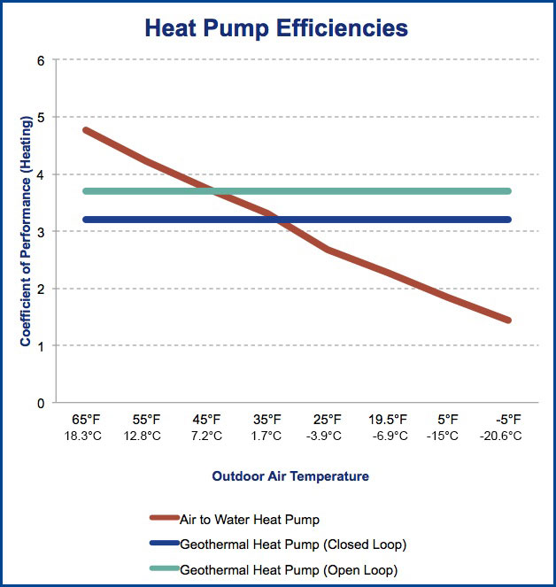
The heat pump COP depends on the pump type. In heat pumps of air-water type, the coefficient varies depending on the outside temperature. In heat pumps of water-water and ground-water types, the COPs are steady (Fig. 4), yet dependent on the source temperature. The COP also depends on the reached output temperature ranging from 35 °C to 55 °C. in the present paper, the values are not given, but they are available in many heat pump manufacturers’ catalogs. [11–14].
To help you take some of the mysterious outcomes of these fluctuating COPs and give you a sense of the heat pump effective temperature range and efficiency at freezing outdoor temperatures, we have mapped how our heat pumps perform at different temperatures.
Figure 4 TheChange of COP depending on the type of heat pump [15].
The data above was taken from an ATW-65 type from Nordic® brand of heat pumps, Maritime Geothermal Ltd. and the equivalent geothermal heat pump (W-65) on both an open and closed geothermal ground loops [15].
4. Declaring general energy prices
sources in Table 2 are determined by an estimate of the price development graphs [16]. The United States have been chosen as the standard price-factor, as they represent a large and economically advanced country. It must be emphasized that the ratios are estimated, and different countries have different values in different periods. Without this estimate, however, future economic efficiency cannot be predicted. EU countries have a huge range of energy prices and presenting the calculation only for some countries would not be fair. However, it is possible to perform a conversion for any country, based on examples.
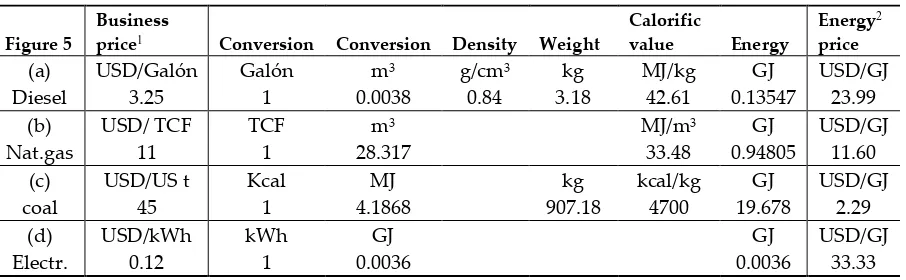
Figures 5 (a-d) illustrate price dependencies of individual energy sources. The estimates of average values for the same period are converted to USD/GJ.
(a)
(c)
(b)
(d)
Figure 5 The blue line shows the changing energy prices for the period 2009 to 2016. TCF (Thousand Cubic Feet), US t (Short Tone) [16].
Table 2 Transactions of the commercial price to the energy price USD / GJ [16].
Figure 5
Business
price1 Conversion Conversion Density Weight
Calorific
value Energy
Energy2
price
(a) USD/Galón Galón m3 g/cm3 kg MJ/kg GJ USD/GJ
Diesel 3.25 1 0.0038 0.84 3.18 42.61 0.13547 23.99
(b) USD/ TCF TCF m3 MJ/m3 GJ USD/GJ
Nat.gas 11 1 28.317 33.48 0.94805 11.60
(c) USD/US t Kcal MJ kg kcal/kg GJ USD/GJ
coal 45 1 4.1868 907.18 4700 19.678 2.29
(d) USD/kWh kWh GJ GJ USD/GJ
Electr. 0.12 1 0.0036 0.0036 33.33
1 Prices are estimated from Figure 3
For the sake of clear comparison, it appears to be appropriate to convert the proportional relationships between individual energy sources into a dimensionless proportional indicator – the effective ratio of energy prices. The effective ratio expresses the ratio between the lowest energy price and other energy prices (11). This dimensionless variable allows for the conversion of energy efficiency into the economic impact. The formulation of effective "p" ratio is listed in Table 3, and if "p" = 1, it indicates the lowest energy source; the more the "p" value approximates "0", the more expensive the source is. The energy price does not include the operating costs of related to the equipment burning a given energy source.
price
energy
other
(coal)
price
energy
lowest
=
p
(11)Table 3 Price ratios of energy sources
Figure
5.
Energy sourcePrice 1GJ [USD]
Effective ratio p
(a) Diesel oil 23.98 0.0953
(b) Natural gas 11.60 0.1971
(c) Coal 2.29 1.0000
(d) Electricity1 33.33 0.0686
1 Electricity used for heat generation.
5. Results
In all cases, except for the one with the electric drive, it is assumed that the heat source is located in the house and the heat from the source is used for heating. For the sake of comparison, coefficient of performance (COP) 3 has been chosen uniformly. As a matter of fact, this is the worst COP value, thus, in reality, it is possible to achieve better results, however with higher investment costs.
5.1. Total thermal efficiency of different heating systems
Figure 6 Energy ratios when heating with a condensing boiler.
Case 2: The overall efficiency of the COP 3 electrically-driven heat pump is given by the formula (9). The expected loss in energy transfer amounts to 10%. The efficiency of the drive is given by the product of the power plant efficiency, the electrical distribution and the electric motor. Figure 7 shows that the heat produced in the power plant has not been used for heating the object in question. This model of heating is often used in modern family houses which have no gas connection, but in which an electrical connection is available. Electricity is produced in a thermal power plant that is only used for electricity generation and not used for heat production. At present, such power plants are still quite numerous.
026
.
1
0
3
95
.
0
9
.
0
4
.
0
−
=
=
EER
(12)
Figure 7 Diagram illustrating the thermal efficiency of the system using an electrically-driven heat pump
Case 3: A Stirling-engine-driven 3-temperature system; a COP 3 Stirling engine-operated heat pump driven by a heating unit (its lowest efficiency being 0.15 according to Table 1). Unlike in Case 2, the HP electric motor drive was replaced with the Stirling engine. We assume that 50% (of energy) is used for driving the Stirling engine, and the remaining 50% is used for direct heating of the interior. Such a method of heating presupposes a natural heat source, such as coal, gas, wood, wood chips or peat that is used for operating the Stirling engine. Unlike the conventional direct heating by a natural energy source used in a combustion boiler, the advantage of the system lies in its significantly lower consumption. The total thermal efficiency calculated by the formula (10) will be as follows:
100
.
1
05
.
0
3
15
.
0
5
.
0
15
.
0
5
.
0
1
−
+
−
=
=
Figure 8 Diagram illustrating the thermal efficiency of system when using a Stirling engine-driven heat pump
Case 4: A three-temperature a four-stroke engine-driven system; a COP 3 four-stroke combustion engine-driven heat pump (its efficiency being 0.25 according to Table 1) the loss heat of which is used for heating shows the overall thermal efficiency calculated by the formula (10). Exhaust gases may be cooled in the system. If compared to Case 3, the advantage of this system is in that the natural energy source is transformed into gas. The gas may be considered as CNG, LPG or other alternatives, whether in a gaseous form transported through a pipeline or in a liquefied form stored in a container. Gas-powered combustion engines are quite common. Thus, in contrast to Case 3, there is no problem handling the solid combustion products and transporting raw materials to the combustion site. The estimated heat waste amounts to approximately 10%.
400
.
1
1
.
0
3
25
.
0
25
.
0
1
−
+
−
=
=
EER
(14)
Figure 9 Diagram illustrating the thermal efficiency of the system using a four-stroke gas-powered combustion engine-driven heat pump
700
.
1
1
.
0
3
4
.
0
4
.
0
1
−
+
−
=
=
EER
(15)
Figure 10 Diagram illustrating the thermal efficiency of the system using a Diesel-powered electric heat pump
5.2. Average increase in three-temperature system efficiency
A three-temperature heating system allows for the increase in the heat supply compared to a two-temperature heat pump system or to a conventional heating system. In order to illustrate the three-temperature energy efficiency, it is appropriate to express the average increase in energy efficiency in percentage compared to the conventional heating method.
(%)
100
.
3 3
EER
EER
EER
p
=
−
(16)3
EER
total energy efficiency of the system3
p
relative increase in the three-temperature system energy efficiencyTable 4 Increase in three-temperature system energy efficiency compared to other heating systems
Three-temperature system
Conventional heating
system p3 (%)
HP Stirling 1 condensing boiler 26
HP four-stroke condensing boiler 53
HP Stirling HP electric drive 14
HP four-stroke HP electric drive 38
HP Stirling electric heater 243
HP four-stroke electric heater 314
1 HP- heat pump
clean operation. The maintenance costs compared with a gas-heated boiler are likely to be higher as the system contains a considerable amount of moveable mechanical components. Moreover, these systems cannot be combined, as is the case of the first combination, because they work independently.
5.3. The overall economic impact of individual heating systems
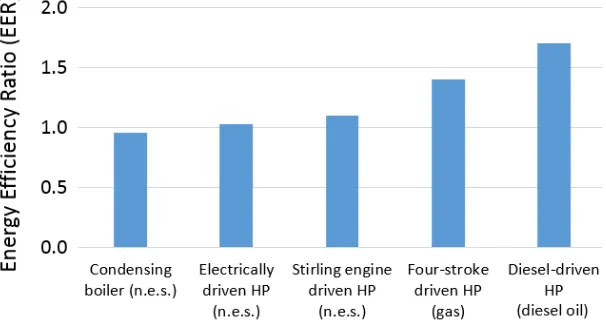
Based on Table 3, the prices of individual sources of energy are used. The economic impact may be estimated by multiplying the overall efficiency of the equipment and the corresponding effective ratio of the energy source. The highest value yields the best result. In Figure 12, the economic relationships between various systems are shown. The higher the value, the more economical the system is.
p
EER
EI
=
(16)Providing the economic impact is only relevant for systems that have the potential for real usage. This applies to the combination of the Stirling engine with a heat pump and a high heat source (such as a boiler). The second possible combination is a four-stroke gas-powered engine and a heat pump. The Diesel engine can manifest high efficiency; however, it is unsuitable from an environmental point of view.
Table 5 Economic and energy advantage of heating systems
Energy
source Device
Energy efficiency
EER
Economic efficiency
EI
coal condensing boiler 0.950 0.950
gas condensing boiler 0.950 0.187
electricity heat pump 1.026 0.070
coal
Stirling three-temperature
system 1.100 1.100
gas
Stirling three-temperature
system 1.100 0.217
gas four-stroke engine 1.400 0.276
Diesel oil Diesel engine 1.700 0.162
The following charts show the results of energy and economic benefits of selected heating systems.
Figure 12 Economic impact of different heating systems (n.e.s. – natural energy source).
7. Discussion
At the first glance of Figure 12, the condensing boiler and, in particular, the Strirling engine-driven and coal-powered HP, appear to be the most advantageous devices. However, it should be noted that the overall economic impact will deteriorate after including the costs of necessary filtering equipment for the eliminating of emissions, transport logistics and storage of coal. After following the policy of gradually reducing the coal economy, we do not consider this path promising.
The thermal efficiency of the three-temperature four-stroke gas-powered engine system is significantly higher than that of the three-temperature Stirling-driven system. The Stirling engine, however, is not dependent on the type of a heat source, which makes it more economical if a cheaper primary source is used (Fig.12).
From the overall analysis it follows that the usage of the Stirling engine or of a similar heat pump drive combined with any high-temperature heat source seems to be the most progressive solution and it increases the efficiency by at least 26% (Table 4). Nevertheless, relatively few publications [18-20] tend to address this issue. However, it can be assumed that future research may follow this direction.
Since the Stirling engine can be produced in various power ranges, the real usage of the three-temperature system is feasible in heating plants and cogeneration power plants. Naturally, with regard to the HP COP, the most preferred HP is a Geothermal HP, Open Loop type, Fig. 4. However, with regard to the initial investment and local options, it is not always beneficial or possible. The usage of a three-temperature system for the production of hot service water is of particular importance. Especially during the summer period, the efficiency of the system may be increased if an air-water HP type is used, since its COP increases along with an increase in the outside temperature (Fig.4).
electricity prices compared with those of the primary energy sources tend to substantially increase, see Table 2. In this respect, there are significant differences among various countries.
In the debates on fuel efficiency, with respect to the view on different energy sources, it is also necessary not to forget in what form and/or in which quality the fuel is supplied. Not every material
– fuel exhibits the same caloric value. For example, organic bio-briquettes produced from wood sawdust through a uniaxial pressing process [21] exhibit various values of density and calorific value. This issue has a significant impact on the diagnostic procedures since the thermal balance considerably influences machine systems. Status monitoring and evaluation of indicators during machine operation are reported by authors in [22.23] research papers. The simulation of heat transfer in the form of mathematical simplification is also dealt with in a paper [25].
When introducing progressive innovation, such as the use of renewed heat, technical considerations need to be taken into account as well [27], as these are among key factors in decisions on introducing such innovation. The issues concerning small and medium-size businesses have been addressed by the authors of the present paper [28]. For buildings, the starting points have been defined and developed in a paper [29].
These calculations of economic impact are merely of informative nature. The calculations have not taken into account such important circumstances as system reliability, investment and operational costs. The study makes use of a nonstandard computational method that can be used in general for other machine systems with regard to machine condition assessment.
A significant limitation in the direction of development in heating systems also arises due to the necessity of compliance with the legislature, which also affects the price. Legislature exercises such an influence that it can fully affect the usage of certain technical devices regardless of the technical solution. For example, as of September 2015, the performance requirements set out in the ErP Directive have been effective with regard to all residential and commercial heating products throughout Europe, including electric power products, boilers and water heaters, as well as renewable technologies, such as solar thermal products and heat pumps. In practice, this means that only condensing boilers may be produced under this directive. It is therefore important to separate the operating economy only in terms of energy consumption, operating economy in terms of founding costs, operating economy in terms of planned and unplanned maintenance costs, while complying with legislation. The present paper focuses on the economic impact with regard to energy consumption without taking into account operational and investment costs. This issue will be the subject of another interesting study.
The benefit of the three-temperature system increases the overall thermal efficiency by a minimum of 26% for any heat source. However, in terms of environmental load, only more environmentally-friendly and sustainable resources ought to be preferred
Acknowledgments: The present study has been supported by the following research grant projects: APVV-15-0149, VEGA 1/0437/17, VEGA 1/0853/16 and KEGA 039TUKE-4/2016. The financial support was granted to cover expenses pertaining to open-access publishing.
Authors´ share in conducting the research and compiling the paper: T. Stejskal and J. Svetlík addressed the theoretical issues of heat pumps. T. Stejskal proposed the equations and the theoretical verification of the Second Law of Thermodynamics. T. Stejskal and J. Svetlík drafted the research paper. P. Demeč and M. Dovica ensured the declaration of general energy prices. M. Štofa and J. Kováč participated in drafting the discussion.
Conflicts of Interest: The authors declare no conflict of interest. The founding sponsors had no role in the design of the study; in the collection, analyses, or interpretation of data; in the writing of the manuscript, and in the decision to publish the results.
References
2. Mardani, A.; Jusoh, A.; Zavadskas, EK.; Cavallaro, F.; Khalifah, Z. Sustainable and Renewable Energy: An Overview of the Application of Multiple Criteria Decision Making Techniques and Approaches. Sustainability 2015, 7, 13947-13984, CCC: 000364328300048.
3. Krizan, P.; Matus, M.; Soos, L.; Beniak, J. Behavior of Beech Sawdust during Densification into a Solid Biofuel. Energies 2015, 8, 6382-6398, CCC: 000359897800008.
4. Takaishi, T.; Numata, A.; Nakano, R.; Sakaguchi, K.Approach to High Efficiency Diesel and Gas Engines. Mitsubishi Heavy Industries Review2008, 45, 21-24.
5. Burt, CM.,; Piao, X.; Gaudi, F.; Busch, B.; Taufik, NN. Electric motor efficiency under variable frequencies and loads. J. Irrig. Drainage Eng-ASCE2008, 134, 129-136, DOI: 10.1061/(ASCE)0733-9437(2008)134:2(129). 6. Baldi, S.; Quang, TL.; Holub, O.; Endel, P. Real-time monitoring energy efficiency and performance
degradation of condensing boilers. Energy Conv. Manag. 2017, 136, 329-339, DOI: 10.1016/j.enconman.2017.01.016.
7. Backhaus, S., Swift, G. W. A thermoacoustic Stirling heat engine. Nature 1999, 399(6734), 335.
8. Viessmann Catalogue – Viessmann Middle East FZE and Viessmann Werke GmbH & Co. KG. Available online: https://www.viessmann.ae/en/the-press/Press-service/Pressetext-09032015-14.html (accessed on 12 October 2018).
9. Martini, William R. Stirling engine design manual. US Department of Energy, Office of Conservation and Solar Applications, Division of Transportation Energy Conservation, 1978.
10. Iwamoto, S., Toda, F., Hirata, K., Takeuchi, M., Yamamoto, T. Comparison of low-and high-temperature differential Stirling engines. In Proceedings of eighth International Stirling engine conference1997, May (pp. 29-38).
11. Heat Pump Catalogue – Mitsubishi Electric. Available online:
https://www.mitsubishi-electric.co.nz/materials/aircon/brochures/@HeatPumpRange.pdf (accessed on 28 February 2018).
12. Heat Pump Catalogue – Fujitsu. Available online:
https://www.fujitsugeneral.co.nz/images/brochures/homerange/retail.pdf (accessed on 28 February 2018). 13. Heat Pump Water Heater – Hubbel. Available online:
http://www.hubbellheaters.com/downloads/catalogs/hubbell_model_pbx.pdf (accessed on 28 February 2018).
14. Deron Heat Pump Catalogue. Available online:
https://www.scribd.com/document/200756881/Deron-Heat-Pump-Catalogue (accessed on 12 October 2018).
15. Nordic® brand of heat pumps, Maritime Geothermal Ltd. Available online:
https://www.nordicghp.com/2017/01/heat-pump-effective-temperature-range (accessed on 28 February 2018).
16. EIA – U.S. Energy Information Administration. Available online:
https://www.eia.gov/todayinenergy/detail.php?id=32912 (accessed on 1 March 2018). 17. Unit Converter Express Version. Available online:
https://www.unitconverters.net/(accessed on 28 June 2018).
18. Walker, G.; Fauvel, R.; Gustafson, R.; Van Bentham, J.Stirling engine heat pumps. International Journal of Refrigeration1982, 5, 91-97.
19. Wang, K.; Sanders, S.R.; Dubey, S.; Choo, F.H.; Duan, F. Stirling cycle engines for recovering low and moderate temperature heat: A review. Renew. Sust. Energ. Rev. 2016, 62, 89-108, DOI:
10.1016/j.rser.2016.04.031.
20. Cho, HJ.; Sarwar, R.; Mago, PJ.; Luck, R. Design and feasibility study of combined heat and power systems integrated with heat pump. Appl. Therm. Eng. 2016, 93, 155-165, DOI: 10.1016/j.applthermaleng.2015.09.027. 21. Vitikac Bateskova, E.; Panda, A. Stroke Design for the Press Roller on the Curling Twincylinder Machine.
Appl. Mech. and Mat.2014, 616, 351-358, DOI: 10.4028/www.scientific.net/AMM.616.351.
22. Baron, P.; Kocisko, M.; Dobransky, J. ; Pollak, M.; Teliskova, M. Research and application of methods of technical diagnostics for the verification of the design node. Measurement 2016, 94, 245-253, DOI: 10.1016/j.measurement.2016.07.089.
23. Dobransky, J.; Baron, P.; Kocisko, M.; Teliskova, M. Monitoring diagnostic indicators during operation of a print machine. Adv. Sci. and Tech.-Res. J. 2015, 9, 34-39, DOI: 10.12913/22998624/60780.
25. Hu, SC.; Shiue, A.; Chiu, YS.; Wang, A. ; Chen, J. Simplified Heat and Mass Transfer Model for Cross-Flow and Countercurrent Flow Packed Bed Tower Dehumidifiers with a Liquid Desiccant System. Sustainability 2016, 8, 1152-1152, DOI: 10.3390/su8121264.
26. Nikitin, Y.; Turygin, Y.; Sosnovich, E.; Bozek, P. Trends in Control of NC Machines, Proceedings of the International conference on manufacturing engineering and materials, ICMEM 2016, Novy Smokovec, Slovakia, June 06-10, 2016; Hloch, S.; Krolczyk, G.; Elsevier Science BV: Amsterdam, Netherlands, 2016, DOI: 10.1016/j.proeng.2016.06.678.
27. Mardani, A.; Jusoh, A.; Zavadskas, EK.; Cavallaro, F.; Khalifah, Z.; Nair, G. Sustainable and Renewable Energy: An Overview of the Application of Multiple Criteria Decision Making Techniques and Approaches. Sustainability 2015, 7, 13947-13984, CCC: 000364328300048.
28. Hjorth, SS.; Brem, AM. How to Assess Market Readiness for an Innovative Solution: The Case of Heat Recovery Technologies for SMEs. Sustainability 2016, 8, 1152-1152, CCC: 000389316200072.


![Table 1 Thermal efficiency of selected engines and equipment [4-8]](https://thumb-us.123doks.com/thumbv2/123dok_us/1078012.1608516/5.595.148.445.564.701/table-thermal-efficiency-selected-engines-equipment.webp)
![Figure 4 The Change of COP depending on the type of heat pump [15].](https://thumb-us.123doks.com/thumbv2/123dok_us/1078012.1608516/6.595.173.427.399.651/figure-change-cop-depending-type-heat-pump.webp)


